Introduction
A reliable design of an antenna array [Reference Ballanis1–Reference Collin3] is a crucial aspect of 5G communication. In recent years, many research proposals aimed at developing practical 5G antenna arrays have been made to improve the spectrum of 5G communications far-field emission pattern characteristics [Reference Kumar, Dixit, Malekar, Raut and Shevada4, Reference Bogucka, Kliks and Kryszkiewicz5]. 5G communication brings several advantages and benefits when compared with its predecessors. The key advantages of 5G communication are high-speed connectivity, low latency, massive device connectivity, enhanced reliability, stability, improved capacity, and efficiency. 5G communication also facilitates the integration of advanced technologies like artificial intelligence (AI), which can support complex applications like autonomous vehicles and intelligent infrastructure. 5G technologies open opportunities for developing new services, business models and industries, including autonomous transportation, smart cities, remote work, telemedicine, etc. These advantages of 5G communications have the potential to revolutionize numerous sectors and pave the way for a more connected and technologically advanced future.
The spectrum allocation for 5G communication is divided into two significant categories, as the International Telecommunication Union Radio Communication (ITU-R) explains. FR1 encompasses frequencies below 6 GHz and FR2 encompasses frequencies above 6 GHz [Reference Kumar, Dixit, Malekar, Raut and Shevada4]. The geometrical configuration, the current excitation of each element, and the spacing among the array’s components are the primary building parameters used to attain the ideal emission pattern (far-field). The 5G band’s increasing freight compelled the array designer to design an array with a narrower half-power beam width (HPBW) and a lower side lobe level (SLL) [Reference Das, Mandal, Ghoshal and Kar6–Reference Das, Mandal and Kar10]. Nonetheless, designing an accurate antenna array in the 5G communication frequency band is impressive while keeping the lower SLL and HPBW, as the two conditions of lower SLL and HPBW value will never be fulfilled simultaneously. Different evolutionary optimization techniques [Reference Das, Mandal and Kar7, Reference Panduro, Brizuela and Acosta11–Reference Panduro, Brizuela, Covarrubias and Lopez20] are also used for optimal emission pattern synthesis of arrays.
Linear antenna arrays (LAA) are decisive in numerous radio system applications, including radar, navigation, and mobile communications. However, recent advancements in wireless technology, especially in the military and 5G communication, have seen a shift toward elliptical antenna arrays (EAAs). The key benefit of EAAs lies in their capability to cover the entire space with their emission pattern, making them increasingly preferable in modern communication systems.
Various stochastic methods are harnessed to refine the far-field emission patterns of LAA. Dib et al. employed the Taguchi technique [Reference Dib, Goudos and Muhsen21], while Khodier et al. utilized particle swarm optimization (PSO) for LAA pattern synthesis [Reference Khodier and Al-Aqeel22]. Biogeography-based optimization (BBO) was implemented in [Reference Sharaqa and Dib23] to optimize LAA and EAA structures, and Symbiotic Organism Search (SOS) was employed by Dib et al. to reduce SLLs in LAA design [Reference Dib24]. Zoubi et al. took a hybrid optimization approach [Reference Zoubi, Amaireh and Dib25] for LAA synthesis. Recent research on optimizing linear, circular antenna arrays, and concentric rings presents a compelling and pragmatic approach [Reference Reyna, Panduro and Rio26–Reference Panduro, Brizuela and Covarrubias34].
Various stochastic optimization techniques have been employed in the design of EAA. Guney and Durmus utilized the backtracking search optimization method [Reference Guney and Durmus35], while the BBO technique was applied for designing both linear and elliptical arrays [Reference Sharaqa and Dib23]. Bera et al. introduced an optimal design approach for EAAs using opposition-based differential evolution [Reference Bera, Mandal, Kar and Ghoshal36]. In [Reference Dib, Amaireh and Zoubi37], the authors rectified previously published literature’s array factor equation errors and harnessed the SOS and ALO techniques to design EAAs. These diverse techniques showcase the adaptability and potential for improving EAA designs and performance.
This study synthesizes the optimal far-field radiation pattern of symmetrical LAA and EAA of dipole element structures. The approach presented here is universal and can be employed for any antenna elements for the identical structure utilizing pattern multiplication. The key benefits and advantages of choosing the SFO algorithm are as follows:
(i) Fast Convergence: The SFO algorithm demonstrates fast convergence rates, quickly converging toward optimal or near-optimal solutions. This makes it convenient for solving complex optimization problems efficiently.
(ii) Efficient exploration-exploitation balance: The SFO algorithm maintains good equity between searching and attacking the search space. It efficiently explores diverse areas to avoid being trapped in local optima, while exploiting promising regions to converge toward the global optima.
(iii) Adaptability: SFO is adaptive, meaning it can dynamically adjust its search behavior based on the characteristics of the problem being solved. It can adapt to different problem domains and efficiently handle various optimization challenges.
(iv) Scalability: The SFO algorithm is scalable and can handle optimization complications of varying sizes and complexities. It can be employed for small-scale and large-scale optimization problems, making it versatile in different application domains.
(v) Parallelization capability: SFO can be parallelized, efficiently utilizing computing resources. It can expedite the optimization process and handle computationally intensive tasks.
(vi) Robustness: The SFO demonstrates robustness and resilience against noisy and uncertain environments. It can handle optimization problems with noisy or incomplete information and provide satisfactory solutions.
(vii) Simplicity and ease of implementation: The SFO algorithm’s underlying principles are relatively straightforward. It does not require complex mathematical formulations or extensive parameter tuning, making it accessible to solve complex optimization problems.
(viii) Potential for real-world applications: The SFO has produced encouraging outputs in solving various optimization problems, including scheduling, engineering design, image processing, data mining, and machine learning. Its effectiveness in real-world applications makes it a valuable tool for problem-solving.
The SFO has demonstrated several advantages in specific scenarios. However, the specific problems determine which optimization algorithm is best and its characteristics and the available resources because, as per the no free launch theorem [Reference Wolpert and Macready38], no superior optimization technique performs the best for figuring out all optimization problems. The SFO is used in this paper to optimize the feeding currents of each LAA and EAA of dipole elements, keeping the phase excitation weight as zero for the contraction of mutual coupling effects between the antenna array elements and to lower the SLL and HPBW values. The elemental spacing among the elements of the LAA is maintained here as d = λ/2, whereas, for the design of EAA, the eccentricity of the ellipse is considered as e = 0.5 for the optimal emission pattern (far-field) synthesis of LAA and EAA in the frequency of 5G communication. The optimal results are presented and correlated with those published in recently divulged articles. They are validated statistically using Computer Simulation Technology (CST)-microwave studio. The results of utilizing the SFO algorithm show a distinguished achievement in designing the symmetrical LAA and EAA of dipole elements.
The remaining portion of the paper is presented in the following manner: Section 2 depicts the design equation of LAA and EAA. Section 3 provides a quick explanation of the stochastic optimization technique used. The SFO algorithm’s numerical, statistical, and EM field simulation-based results are presented and juxtaposed with those from other contemporary published literature in Section 4. Lastly, Section 5 brings the article to a conclusion.
Parametric assimilation technique (PAT)
The PAT is employed for mutual coupling withering in antenna arrays. It aims to minimize the mutual coupling, which occurs when antennas in an array interfere, degrading the antenna array performance. The methodologies involved in PAT are discussed in detail in [Reference Das, Mandal and Kar18, Reference Chakravorty and Mandal39] and are given in a flowchart in Fig. 1.
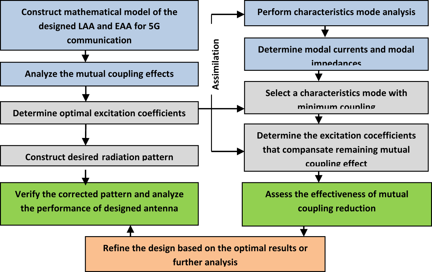
Figure 1. Flow chart of the PAT.
Array model and mutual coupling analysis:
i. Construct a mathematical model of the antenna array considering the physical characteristics and position of the antennas.
ii. Analyze the mutual coupling effects between the antenna elements in the array using numerical methods and obtain the mutual coupling matrix that represents the interactions between the antennas.
Antenna pattern synthesis:
i. Define the desired radiation pattern or beam-forming requirements for the antenna array.
ii. Use a suitable optimization technique to determine the exact excitation coefficients for the antennas.
iii. The optimization aims to synthesize the desired radiation pattern while considering the mutual coupling effects.
Characteristics mode analysis (CMA):
i. Perform a characteristic mode analysis (CMA) to identify the dominant characteristic modes of the antenna array.
ii. Determine the modal currents and characteristic mode impedances associated with each mode.
iii. CMA helps understand each antenna’s current distribution and the coupling between them.
Mode selection and excitation optimization:
i. Select a subset of characteristic modes that have minimum coupling with each other.
ii. Modify the excitation coefficients of the antennas to suppress the coupling effects and minimize the mutual coupling effects.
iii. Use optimization techniques to find the excitation coefficients that compensate for the remaining mutual coupling effects.
Electromagnetic simulation and analysis:
i. Validate the performance of the decoupled antenna array using electromagnetic simulation tools.
ii. Analyze the radiation pattern, impedance matching, and other relevant parameters to assess the effectiveness of the mutual coupling reduction.
Iterative refinement:
i. Iterate through the previous steps if necessary to further optimize the antenna array’s performance.
ii. Adjust the excitation coefficients and refine the design based on the results or further analysis.
The specific implementation details and techniques within PAT may vary depending on the antenna array configuration, requirements and available resources. It is essential to carefully analyze and model the array characteristics, optimize the excitation coefficients, or refine the design based on the results or further analysis.
Design equation
Linear antenna array
The LAA’s geometry is formed by symmetrically positioning 2 M (where M is an integer) isotropic array elements along the z-axis, as shown in Fig. 2, M elements on each side of the origin, separated by d = λ/2. The feeding currents are distributed symmetrically on each element of the array. Hence, the LAA’s broadside array factor (AF) is denoted by (1):
 \begin{equation}{\left( {AF} \right)_{2M}} = 2\mathop {\mathop \sum \nolimits }\limits_M^{n = 1} {I_n}\cos \left[ {\left( {\frac{{2n - 1}}{2}} \right) \cdot k \cdot d \cdot \cos \theta + {\phi _n}} \right].\end{equation}
Figure 2. 2 M-elements LAA geometry along the Z-axis.
The phase excitation weights are kept to zero to keep the far-field radiation pattern’s central beam stable and fixed, where n denotes the nth element of the array and In shows the feeding current of the nth element of the array.
2 M gives the total antenna elements present in the LAA. d and k describe the elemental separation and the wave propagation constant. Ɵ denotes the angle of radiation.
Elliptical antenna array
The EAA is constructed by placing N number of array elements in the geometry of an ellipse positioned on the x–y plane, as shown in Fig. 3. Dib et al. described the array factor (AF) of the EAA in [Reference Dib, Amaireh and Zoubi37], which is given by (2):
 \begin{equation}AF(\theta ,\varphi ) = \mathop {\mathop \sum \nolimits }\limits_N^{n = 1} {I_n}\exp [\,jk{\rho _n}\sin \theta \cos (\varphi - {\varphi _n}) + j{\alpha _n}],\end{equation}
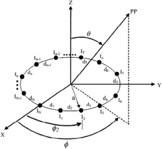
Figure 3. N elements EAA geometry.
where N indicates the number of array elements included in the EAA. The feeding current and the phase excitation weight of the EAA are represented by In and αn, respectively. The αn is determined as (3):
where the wave propagation constant is represented by k. The EAA’s radial distance for the nth element is denoted as ρn, while its angular position is described in (4):
 \begin{equation}{\varphi _n} = \frac{{2\pi (n - 1)}}{N}.\end{equation}
 The values of θ 0 and ![]() ${\varphi _0}$ are represented by 90° and 0°, respectively, as the central lobe of EAA faces the positive x-axis. The angle θ is 90° since the EAA is in the XY plane. The eccentricity (e = 0.5) is the ratio between the ellipse’s vertices and foci, as described in (5):
${\varphi _0}$ are represented by 90° and 0°, respectively, as the central lobe of EAA faces the positive x-axis. The angle θ is 90° since the EAA is in the XY plane. The eccentricity (e = 0.5) is the ratio between the ellipse’s vertices and foci, as described in (5):
 \begin{equation}e = \sqrt {1 - \frac{{{b^2}}}{{{a^2}}}} ,\end{equation}
here “a” represents the semi-major axis and its value varies with the number of elements in the EAA (8-, 12-, and 20-element), corresponding to 0.5λ, 1.15λ, and 1.6λ [Reference Guney and Durmus35–Reference Dib, Amaireh and Zoubi37].
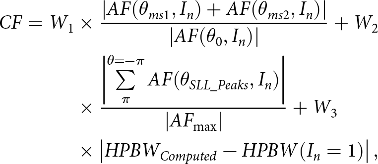
A precise LAA and EAA structure design for applying 5G communication requires developing a convenient cost function (CF) that can abridge the SLL and HPBW value as given in (6):
 \begin{align}CF = {W_1} &\times \frac{{\left| {AF({\theta _{ms1}},{I_n}) + AF({\theta _{ms2}},{I_n})} \right|}}{{\left| {AF({\theta _0},{I_n})} \right|}} + {W_2} \nonumber\\ &\times \frac{{\left| {\mathop {\mathop \sum \nolimits }\limits_\pi ^{\theta = - \pi } AF({\theta _{SLL\_Peaks}},{I_n})} \right|}}{{\left| {A{F_{\max }}} \right|}} + {W_3} \nonumber\\ &\times \left| {HPB{W_{Computed}} - HPBW({I_n} = 1)} \right|,\end{align}
 W 1, W 2, and W 3 are weighting factors with values of 0.5, 0.6, and 0.6, respectively. θ 0 represents the angle corresponding to the peak value of the central lobe. The angles θms 1 and θms 2 indicate the highest side lobe angles for lower and upper angles of arrival from the main lobe, respectively. “In” denotes the feeding current for the nth element. HPBWComputed and HPBW (In=1) represent HPBW values for non-uniform and uniform excitation, respectively, and are considered only in cases where HPBWComputed exceeds HPBW(In =1). The third term of the CF is employed to reduce HPBW, while the second term minimizes the value of SLL by strategically positioning nulls at the peaks of each side lobe in the far-field emission pattern. The summation of all the side lobe peaks is expressed by  $\sum\limits_{\theta = - \pi }^\pi {\left( {{\theta _{SLL\_Peaks}},{I_n}} \right)} $ where
 ![]() $\theta \in \left[ { - \pi :{\theta _{ms1}},{\theta _{ms2}}:\pi } \right]$.
$\theta \in \left[ { - \pi :{\theta _{ms1}},{\theta _{ms2}}:\pi } \right]$. ![]() $\left| {A{F_{\max }}} \right|$ is represented as the highest value of AF. In this paper, SFO regulates the current amplitude excitation weights to reduce the CF value.
$\left| {A{F_{\max }}} \right|$ is represented as the highest value of AF. In this paper, SFO regulates the current amplitude excitation weights to reduce the CF value.
Sailfish optimization (SFO)
The development of sailfish optimization (SFO) as a meta-heuristic optimization technique is motivated by the group hunting behavior of sailfish. Shadravan et al. developed and analytically designed the SFO technique [Reference Shadravan, Naji and Bardsiri40]. The evolutionary algorithms have been applied successfully in several engineering problems during the last few decades because multiple agents frequently share knowledge using meta-heuristic methods, which helps the algorithm achieve the highest quality solutions in the search space. Whether a meta-heuristic algorithm effectively solves a specific optimization problem depends on the proper balance between the algorithm’s searching and attacking phases. While the exploitation phase more thoroughly explores the favorable area of the entire search space, the exploration phase tries to manage the displacement of agents as randomly as possible throughout the search space.
The SFO technique draws inspiration from the sailfish group’s hunting behaviors, which alternatively attack the prey of sardines. The reputation of the SFO algorithm compared to the other recently published meta-heuristic optimization techniques are as follows: (i) Firstly, in SFO, the prey and predator populations are divided into two groups to determine the hunting strategy of the group. (ii) Secondly, in SFO, the collective defence of the prey is broken by the alternation of the attack. (iii) Thirdly, the prey movement in the search space is updated in SFO to allow the hunter to become fitter and enriched with the previous experience to catch the appropriate prey. The behavior of sailfish and its prey in the SFO technique is mathematically modeled by Shadravan et al. [Reference Shadravan, Naji and Bardsiri40], which is briefly addressed in the steps below.
Initialization
Sailfishes are considered potential solutions in SFO, and their locations in the solution space correspond to the variables that make up the problem. The SF matrix represents the positions of all sailfishes, which shows the variables of all solutions in the optimization problem:
 \begin{equation}S{F_{position}} = \left[ {\begin{array}{*{20}{c}}
{S{F_{1,1}}}&{S{F_{1,2}}}& \cdots &{S{F_{1,d}}} \\
{S{F_{2,1}}}&{S{F_{2,2}}}& \cdots &{S{F_{2,d}}} \\
\vdots & \vdots & \vdots & \vdots \\
{S{F_{m,1}}}&{S{F_{m,2}}}& \cdots &{S{F_{m,d}}}
\end{array}} \right],\end{equation}
\begin{equation}S{F_{position}} = \left[ {\begin{array}{*{20}{c}}
{S{F_{1,1}}}&{S{F_{1,2}}}& \cdots &{S{F_{1,d}}} \\
{S{F_{2,1}}}&{S{F_{2,2}}}& \cdots &{S{F_{2,d}}} \\
\vdots & \vdots & \vdots & \vdots \\
{S{F_{m,1}}}&{S{F_{m,2}}}& \cdots &{S{F_{m,d}}}
\end{array}} \right],\end{equation}where d is the number of sailfish and m is the number of variables. The fitness function determines each sailfish’s fitness as given in (8):
 \begin{equation}S{F_{Fitness}} = \left[ {\begin{array}{*{20}{c}}
{f(\begin{array}{*{20}{c}}
{S{F_{1,1}}}&{S{F_{1,2}}}& \cdots &{S{F_{1,d}}}
\end{array})} \\
{f(\begin{array}{*{20}{c}}
{S{F_{2,1}}}&{S{F_{2,2}}}& \cdots &{S{F_{2,d}}}
\end{array})} \\
\vdots \\
{f(\begin{array}{*{20}{c}}
{S{F_{m,1}}}&{S{F_{m,2}}}& \cdots &{S{F_{m,d}}}
\end{array})}
\end{array}} \right] = \left[ {\begin{array}{*{20}{c}}
{{F_{SF1}}} \\
{{F_{SF2}}} \\
\vdots \\
{{F_{SFm}}}
\end{array}} \right],\end{equation}
\begin{equation}S{F_{Fitness}} = \left[ {\begin{array}{*{20}{c}}
{f(\begin{array}{*{20}{c}}
{S{F_{1,1}}}&{S{F_{1,2}}}& \cdots &{S{F_{1,d}}}
\end{array})} \\
{f(\begin{array}{*{20}{c}}
{S{F_{2,1}}}&{S{F_{2,2}}}& \cdots &{S{F_{2,d}}}
\end{array})} \\
\vdots \\
{f(\begin{array}{*{20}{c}}
{S{F_{m,1}}}&{S{F_{m,2}}}& \cdots &{S{F_{m,d}}}
\end{array})}
\end{array}} \right] = \left[ {\begin{array}{*{20}{c}}
{{F_{SF1}}} \\
{{F_{SF2}}} \\
\vdots \\
{{F_{SFm}}}
\end{array}} \right],\end{equation}where m denotes the number of sailfish present in the matrix and SFi,j shows the value of ith sailfish at the jth dimension, and f calculates the fitness function. Each sailfish’s fitness value is stored in the SFFitness matrix.
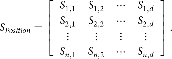
The group of sardine fish, which is assumed to move around the search space, plays another vital role in the SFO optimization technique. The Sposition and SFitness matrix contain the locations of the sardines and each one’s fitness value, respectively, as given in (9) and (10).
 \begin{equation}{S_{Position}} = \left[ {\begin{array}{*{20}{c}}
{{S_{1,1}}}&{{S_{1,2}}}& \cdots &{{S_{1,d}}} \\
{{S_{2,1}}}&{{S_{2,2}}}& \cdots &{{S_{2,d}}} \\
\vdots & \vdots & \vdots & \vdots \\
{{S_{n,1}}}&{{S_{n,2}}}& \cdots &{{S_{n,d}}}
\end{array}} \right].\end{equation}
\begin{equation}{S_{Position}} = \left[ {\begin{array}{*{20}{c}}
{{S_{1,1}}}&{{S_{1,2}}}& \cdots &{{S_{1,d}}} \\
{{S_{2,1}}}&{{S_{2,2}}}& \cdots &{{S_{2,d}}} \\
\vdots & \vdots & \vdots & \vdots \\
{{S_{n,1}}}&{{S_{n,2}}}& \cdots &{{S_{n,d}}}
\end{array}} \right].\end{equation}The SPosition matrix represents the position of all sardines, whereas n and d represent the number and the dimension of sardines, respectively:
 \begin{equation}{S_{Fitness}} = \left[ {\begin{array}{*{20}{c}}
{f(\begin{array}{*{20}{c}}
{{S_{1,1}}}&{{S_{1,2}}}& \cdots &{{S_{1,d}}}
\end{array})} \\
{f(\begin{array}{*{20}{c}}
{{S_{2,1}}}&{{S_{2,2}}}& \cdots &{{S_{2,d}}}
\end{array})} \\
\vdots \\
{f(\begin{array}{*{20}{c}}
{{S_{n,1}}}&{{S_{n,2}}}& \cdots &{{S_{n,d}}}
\end{array})}
\end{array}} \right] = \left[ {\begin{array}{*{20}{c}}
{{F_{S1}}} \\
{{F_{S2}}} \\
\vdots \\
{{F_{Sn}}}
\end{array}} \right],\end{equation}
\begin{equation}{S_{Fitness}} = \left[ {\begin{array}{*{20}{c}}
{f(\begin{array}{*{20}{c}}
{{S_{1,1}}}&{{S_{1,2}}}& \cdots &{{S_{1,d}}}
\end{array})} \\
{f(\begin{array}{*{20}{c}}
{{S_{2,1}}}&{{S_{2,2}}}& \cdots &{{S_{2,d}}}
\end{array})} \\
\vdots \\
{f(\begin{array}{*{20}{c}}
{{S_{n,1}}}&{{S_{n,2}}}& \cdots &{{S_{n,d}}}
\end{array})}
\end{array}} \right] = \left[ {\begin{array}{*{20}{c}}
{{F_{S1}}} \\
{{F_{S2}}} \\
\vdots \\
{{F_{Sn}}}
\end{array}} \right],\end{equation}SFitness represents the fitness value of each sardine. Sardines and sailfish are two crucial, interrelated aspects of the SFO algorithm, where sardines uphold to detect the best place in the search space. In contrast, sailfish are dispersed throughout the search area.
Elitism
During the position update of search agents, the excellent solution is sometimes lost with the comparatively weaker solution when the method of elitist choice is not used. The elitist approach entails reproducing the winner-take-all strategy in the SFO algorithm. The SFO algorithm also employs elitism, where the best sailfish position in every iteration is saved, reflecting the elite’s position. At the same time, the wounded sardine position is preserved, elected as the sailfish’s best target. ![]() $X_{elite\_SF}^i$ and
$X_{elite\_SF}^i$ and  $X_{injured\_S}^i$ represents the sailfish’s elite position and wounded sardines at ith iteration.
Attack alternation strategy
The hunting mechanism of the sailfish supports the attack alternation method in the SFO algorithm, where the exploration phase involves a wide area of search space to find favorable solutions. The sailfish attack in all directions of the search space within a timid circle and update where they stand with the ideal response.
In SFO at the ith generation, the sailfish’s new location ![]() $X_{new\_SF}^i$ is updated as (11):
$X_{new\_SF}^i$ is updated as (11):
 \begin{align}X_{new\_SF}^i = &X_{elite\_SF}^i - {\lambda _i} \nonumber\\ &\times \left( {rand(0,1)\times\left( {\frac{{X_{elite\_SF}^i + X_{injured\_S}^i}}{2}} \right) - X_{old\_SF}^i} \right),\end{align}
 ![]() $X_{elite\_SF}^i$ and
$X_{elite\_SF}^i$ and  $X_{injured\_S}^i$ represent the elite sailfish’s position and the injured sardine’s best position, respectively. The location of sailfish right now is
 ![]() $X_{old\_SF}^i$ and rand(0,1) is the random number between 0, 1, and λi is the coefficient of ith generation and is given by (12):
$X_{old\_SF}^i$ and rand(0,1) is the random number between 0, 1, and λi is the coefficient of ith generation and is given by (12):
where prey density (PD) is the number of prey at each iteration which decreases by the sailfish hunting mechanism. The PD is crucial in SFO for updating the sailfish’s location relative to the prey school, as stated in (13):
 \begin{equation}PD = 1 - \left( {\frac{{{N_{SF}}}}{{{N_{SF}} + {N_S}}}} \right),\end{equation}
 NSF denotes the number of sailfish, and NS stands for the number of sardines at each iteration cycle. Because there are more sardines than sailfish at first, NSF is calculated as ![]() ${N_S} \times pp$, where pp is the proportion of the sardine population that makes up the initial sailfish population.
${N_S} \times pp$, where pp is the proportion of the sardine population that makes up the initial sailfish population.
Hunting and catching prey
In SFO, the sailfish are initially more eager to catch the prey, whereas sardines also have more energy to maintain a high escape speed. The attacking power of sailfish gradually decreased throughout the iteration. The sardine (prey) loses energy due to the sailfish’s repeated and violent attacks, which could impair its ability to recognize directional details regarding its location and impact how it moves. The new position of sardines in the SFO technique in the ith generation is given by (14):
where ![]() $X_{elite\_SF}^i$ represents the elite sailfish position and
$X_{elite\_SF}^i$ represents the elite sailfish position and ![]() $X_{old\_S}^i$ is the location of the sardines right now, r is a random value between 0 and 1, and the strength of the sailfish attack during each iteration is represented by AP, given by (15):
$X_{old\_S}^i$ is the location of the sardines right now, r is a random value between 0 and 1, and the strength of the sailfish attack during each iteration is represented by AP, given by (15):
where A and ε are the coefficients inversely correlated with attacking power, the sailfish’s attacking capability will diminish throughout the iteration, which can help the search agents converge through adaptation. The number of sardines updating their location (α) with the number of variables (β) is given by (16) and (17), respectively,
where di represents the number of variables at ith iteration, and NS represents the quantity of sardines in each cycle.
Now, α sardines with β variables will be updated if the sailfish tap intensity is low (AP < 0.5), and all sardine positions will be updated if the sailfish tap intensity is high ![]() $\left( {AP \geqslant 0.5} \right)$.
$\left( {AP \geqslant 0.5} \right)$.
Finally, in the SFO technique, the sailfish change the position to increase the likelihood of pursuing fresh prey, as indicated by the most updated position of the chased sardine, which is given by (18):
where ![]() $X_S^i$ stands for the current position of the sardine at the ith iteration and
$X_S^i$ stands for the current position of the sardine at the ith iteration and ![]() $X_{SF}^i$ represents the current position of the sailfish at the ith iteration, respectively. The flow chart of the SFO technique is shown in Fig. 4.
$X_{SF}^i$ represents the current position of the sailfish at the ith iteration, respectively. The flow chart of the SFO technique is shown in Fig. 4.
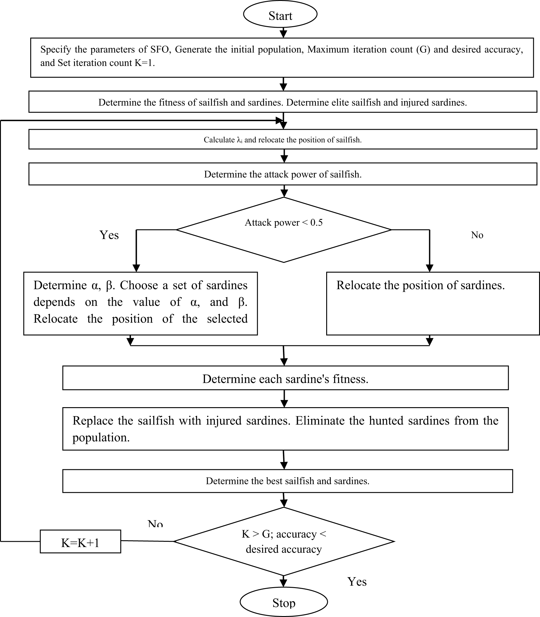
Figure 4. Flowchart for SFO algorithm.
Results and discussion
The feeding currents to the elements of symmetrical LAA and EAA structure of dipole element design are achieved by the execution of the SFO algorithm extensively. The SFO algorithm was independently executed 50 times employing MATLAB R2007b with the Intel core i5 processor, 2.59 GHz with 8 GB RAM. Based on the control parameters given in Table 1, the best performance is showcased among all the outcomes.
Table 1. SFO control parameters

Numerical results of symmetrical linear antenna array
The SFO technique has been utilized in this paper to achieve the emission pattern of the symmetrical LAA. The SFO technique yields reduced HPBW and SLL in symmetrical LAAs with 10 and 16 elements. Further insights on evolutionary optimization parameter tuning can be found in [Reference Eiben and Smit41]. The best control parameters of the SFO algorithm for designing the symmetrical LAA are given in Table 1. The SFO algorithm designs symmetrical LAAs with λ/2 inter-element spacing, and the corresponding feeding currents are documented in Table 2.
Table 2. The feeding currents (In) of symmetrical (d = λ/2) linear antenna array employing the SFO technique
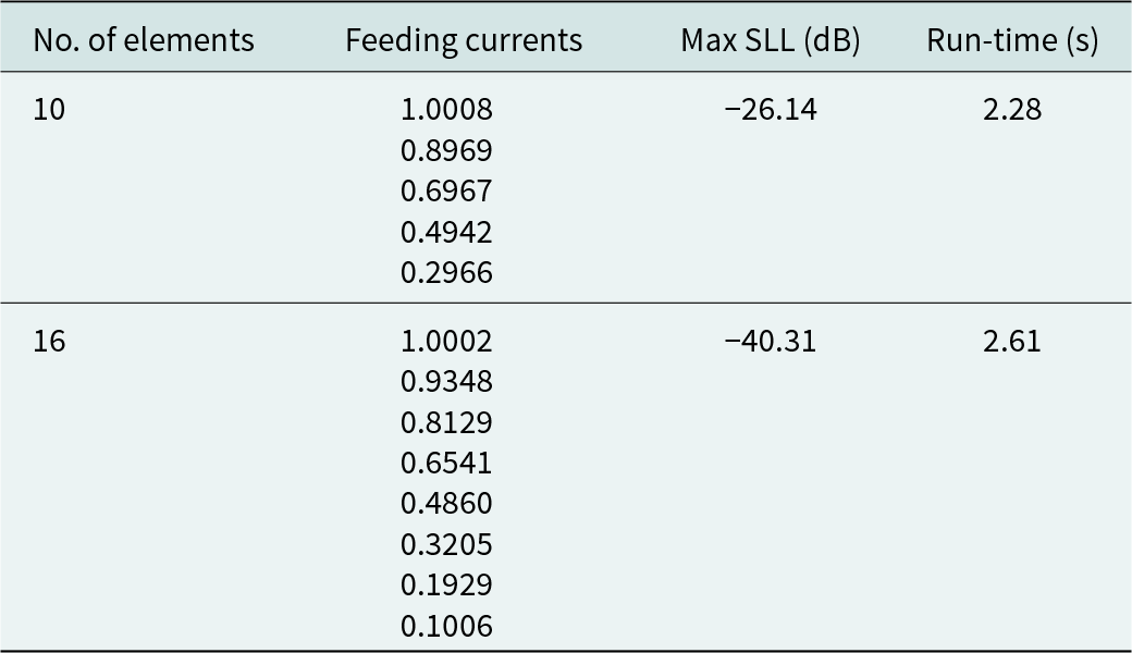
The SLL values accomplished by employing the SFO algorithm for the symmetrical 10, 16-element LAA design are −26.14 and −40.31 dB, respectively. The SFO algorithm requires 2.28 and 2.61 s, respectively, to achieve the optimal value of the feeding current of symmetrical LAA (10-, 16-element).
Figure 5 illustrates the emission pattern (far-field) of a 10-element symmetrical LAA constructed using the SFO algorithm. This pattern is accomplished by applying the SFO technique with the proclaimed pattern obtained in the contemporary published article where the effect of mutual coupling was not considered, as depicted in Table 3.

Figure 5. Radiation patterns of 10-element LAA.
Table 3. Comparative performance of SFO-based 10-element symmetrical LAA with other algorithms
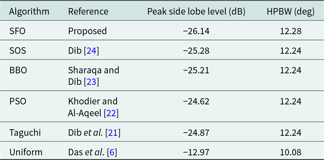
SFO based results for the design of a symmetrical 10-element LAA are compared in Table 3. These results are contrasted with those found in contemporary literature, where mutual coupling effects were neglected. Table 4 extends this comparison to the design of a 16-element LAA using the SFO technique, with results reported in a recent article.
Table 4. Comparative performance of SFO-based 16-element symmetrical LAA with other algorithms
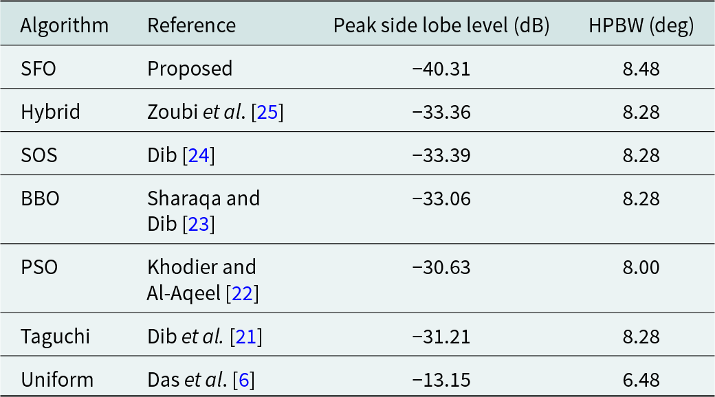
Figure 6 illustrates the far-field radiation pattern achieved by employing the SFO for the 16-element symmetrical LAA. This emission pattern starkly contrasts the pattern reported in contemporary literature, where mutual coupling effects were disregarded, as indicated in Table 4.
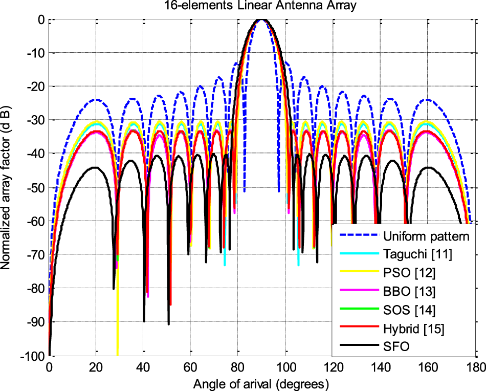
Figure 6. Radiation patterns of 16-element LAA.
The numerical findings for designing 10- and 16-element LAA structures, considering the mutual coupling effects for 5G communication applications, underscore the remarkable optimization capabilities of the SFO algorithm. These results contrast sharply with contemporary literature, where mutual coupling effects were not considered.
Numerical results of elliptical antenna array
The emission pattern of thinned 8-, 10-, and 20-element EAAs in the far field is optimized through the SFO technique. Thinning the antenna array involves removing certain elements from the symmetric array to overcome adjacency constraints. SFO results demonstrate reduced HPBW and SLL for 8-, 12-, and 20-element symmetrical EAAs, maintaining the ellipse’s constant eccentricity (e = 0.5), which measures the distance between its foci and vertices. A comparison of SFO outcomes with uniform feeding currents across all EAA elements and with literature lacking mutual coupling consideration reveals the technique’s effectiveness in enhancing antenna performance.
Table 5 presents the SLL and HPBW values for three different EAA configurations (8, 12, and 20 elements) with uniform feeding currents and a fixed eccentricity (e = 0.5).
Table 5. Comparison of sidelobe level (SLL) and half power beamwidth (HPBW) in uniformly excited and symmetric eccentricity (e = 0.5) EAA with varying element counts

In Table 6, we observe the feeding currents for thinned EAA designs (8, 12, and 20 elements) that consider mutual coupling effects optimized using the SFO algorithm. This table also displays the SLL and HPBW values and the execution time required by the SFO algorithm to optimize the EAA structures. The results indicate that the SLL values for the three EAA structures are −14.78, −8.08, and −12.66 dB, while the HPBW values are 49°, 22°, and 17°, respectively. The SFO algorithm takes 4.12 s for 8 elements, 4.55 s for 12 elements, and 4.89 s for 20 elements EAA structures design.
Table 6. The results based on the SFO algorithm for the design of EAAs of the same eccentricity (e = 0.5)
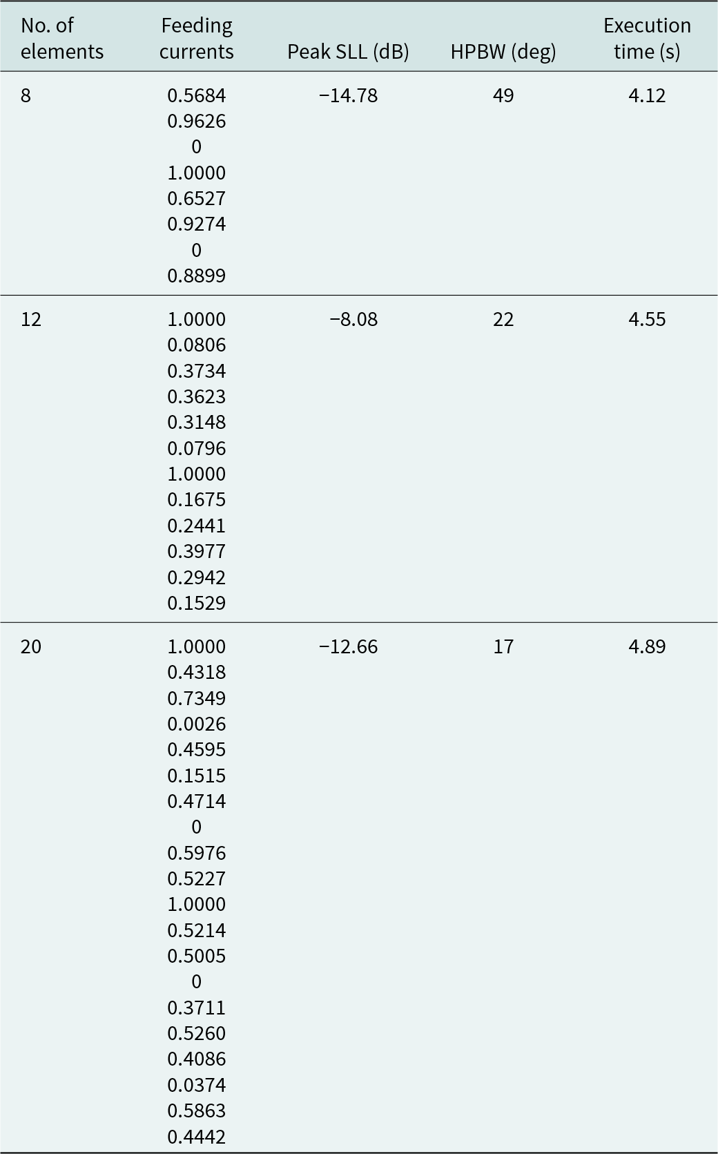
To weigh the effectiveness of the SFO algorithm, Table 7 provides a comparison between SLL and HPBW values for the design of 8-element thinned EAAs using the SFO algorithm and the results reported in a recent article. This analysis aids in understanding the algorithm’s performance and alignment with existing research.
Table 7. Comparative analysis of SFO-based performance in 8-element EAAs with existing results

Various meta-heuristic techniques were used to design an 8-element EAA, with the results summarized in Table 7 and illustrated in Fig. 7. The SFO technique, when applied to design thinned EAA, achieved superior peak SLL values compared to other optimization methods that did not account for array thinning and mutual coupling effects, as depicted in Fig. 7. Table 8 compares the results obtained using the SFO algorithm, and those from recently published articles focused on designing 12-element EAAs without considering the mutual coupling and array thinning. Figure 8 illustrates the emission pattern (far-field) of 12-element EAA achieved by employing SFO. The radiation patterns obtained by applying the SFO algorithm and the proclaimed emission pattern in the contemporary published literature are plotted in Fig. 8, with the data displayed in Table 8. The illustration depicts superior peak SLL and HPBW suppression by the SFO algorithm compared with competing stochastic optimization methods. The results obtained from the SFO algorithm for suppressing SLL and HPBW value are compared with those obtained in the state-of-the-art articles where the mutual coupling effect is not contemplated for designing 20-element EAA, which are given in Table 9.
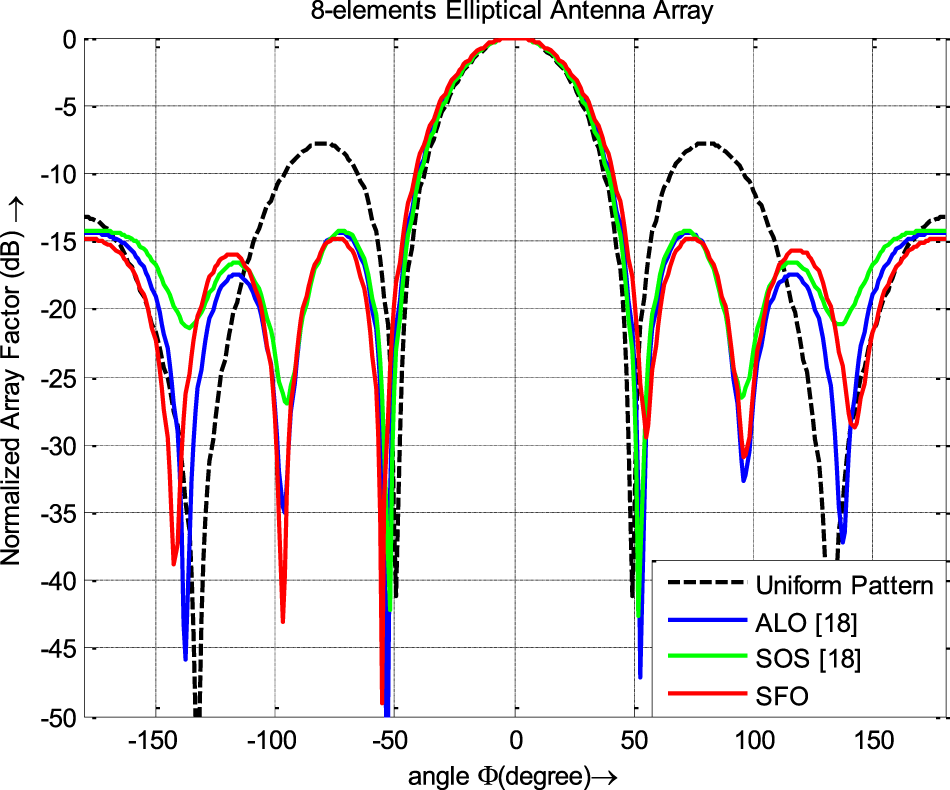
Figure 7. Radiation patterns of 8-element EAA.
Table 8. Comparative analysis of SFO-based performance in 12-element EAAs with existing results

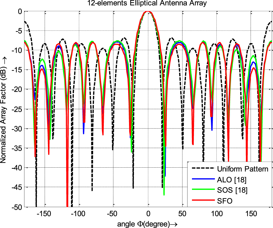
Figure 8. Radiation patterns of 12 elements EAA.
Table 9. Comparative analysis of SFO-based performance in 20-element EAAs with existing results

The emission pattern of the 20-element EAA achieved using the SFO algorithm is plotted in Fig. 9. The radiation pattern from the existing literature is included in the same figure, highlighting the superior performance of the SFO algorithm in comparison to other contemporary optimization techniques that neglect mutual coupling effects in the design of 20-element EAAs.
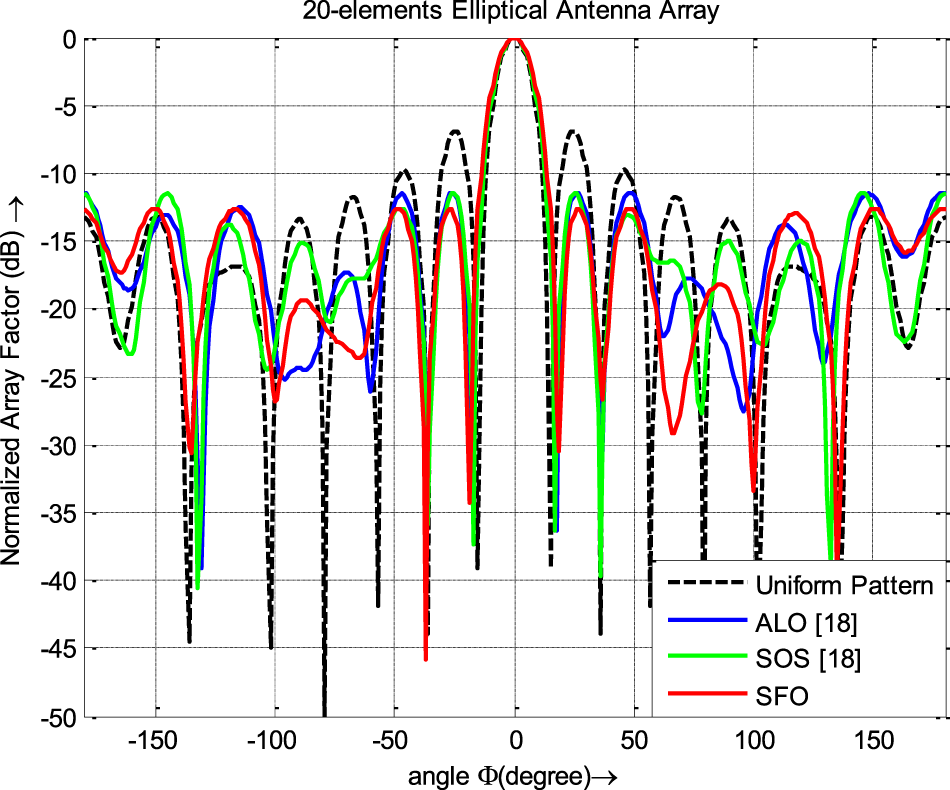
Figure 9. Emission patterns of 20-element EAA.
Electromagnetic simulation-based results
In this study, the efficacy of the SFO algorithm in designing optimal LAA and EAA for the 5G communication spectrum is verified. The validation uses microwave studio (CST-MS), employing electromagnetic field simulations.
CST-MS is a dynamic software tool for electromagnetic simulation and designing microwave and RF components and systems. It is developed and maintained by Computer Simulation Technology (CST), a leading provider of electromagnetic simulation software. Figures 10 and 11 show the dipole antenna and its radiation pattern for estimating directivity.

Figure 10. Designed half-wave dipole antenna.

Figure 11. The far-field radiation pattern of the half-wave dipole antenna.
Table 10 presents design specifications and results obtained through CST-MS, matching feeding currents and fundamental separation values from simulations using the SFO method for 10 and 16-element LAAs and 8-, 12-, and 20-element EAAs.
Table 10. CST-MS based results for the design of LAA and EAA structures
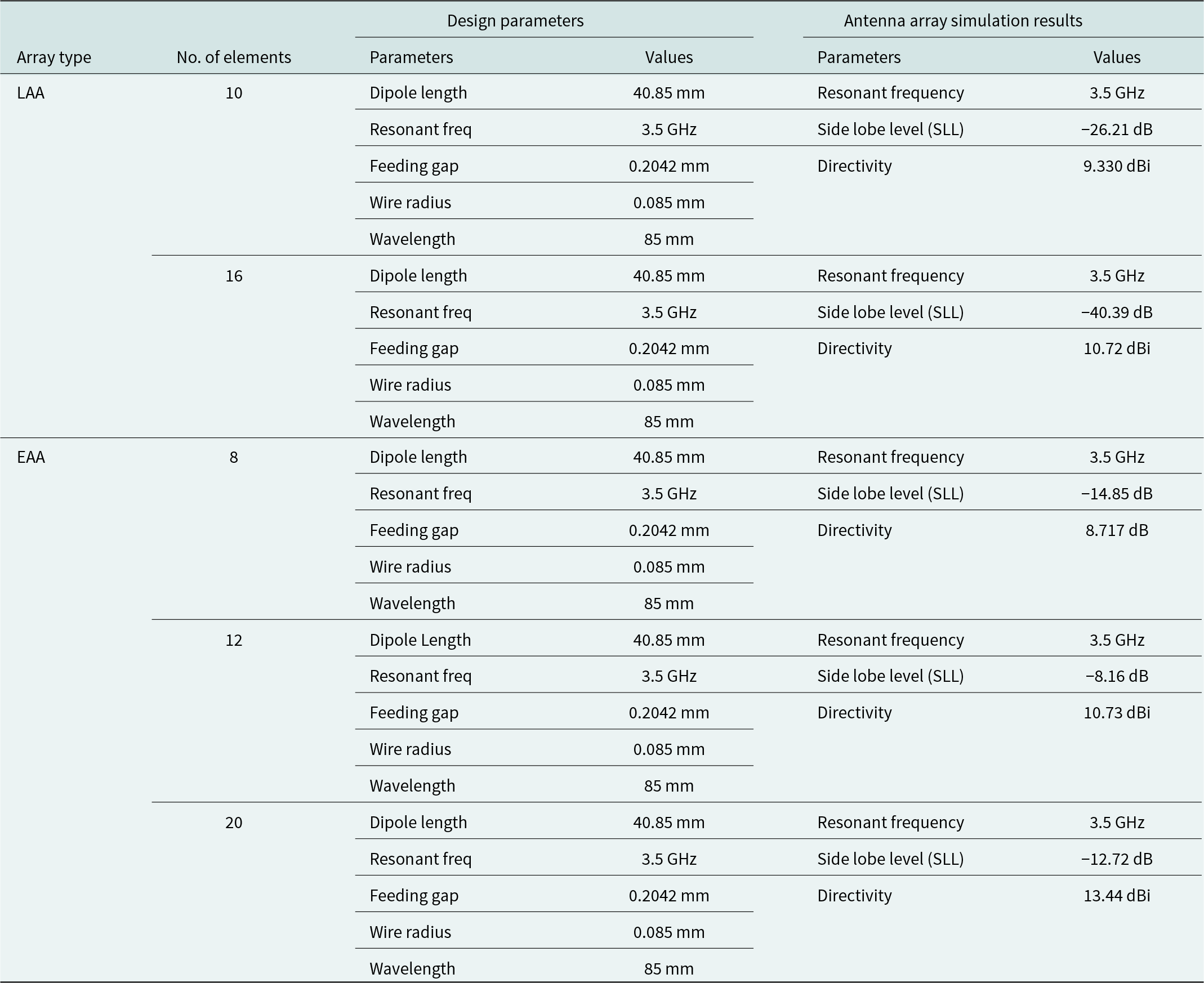
The emission patterns (far-field) of LAA (10 elements and 16 elements) as determined by CST-MS are shown in Figures 12 and 13. Table 10 displays the directivity and SLL values determined using CST-MS for the 10- and 16-element LAA designs.
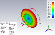
Figure 12. The far-field emission pattern of 10-element LAA accomplished by CST-MS.

Figure 13. The far-field emission pattern of 16-element LAA accomplished by CST-MS.
The SFO technique-based outcomes of the emission patterns (far-field) for the design of (8, 12, and 20) elements EAA by employing CST-MS are presented in Figures 14–16, respectively. Table 10 displays the directivity values that were determined for the various scenarios.
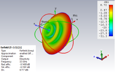
Figure 14. The far-field emission pattern of 8 elements EAA accomplished by CST-MS.

Figure 15. The far-field emission pattern of 12 elements EAA accomplished by CST-MS.

Figure 16. The far-field emission pattern of 20 elements EAA accomplished by CST-MS.
Table 10 highlights the SFO’s efficacy in optimizing the LAAs and EAAs for 5G communication, as it demonstrates the maximum SLL values attained with CST-MS in specific scenarios, affirming its success.
The performance of SFO based LAA and EAA structures analysis based on statistical methods
The statistical parameters in Table 11, derived from the SFO algorithm’s application in designing LAAs and EAAs, reveal minimal variation in the cost function (CF). These results in Table 11 validate the stability of the SFO algorithm for both LAA and EAA designs.
Table 11. Statistical analysis of SFO algorithm for LAA and EAA design (CF results)

Box-and-whisker plots
This paper presents Box-and-whisker plots [Reference Das, Mandal and Kar8] illustrating the design of LAA with 10 and 16 elements and EAA with 8, 12, and 20 elements, using the SFO technique. The box-and-whisker plots are based on CF values collected from each run, with the top and bottom boundaries of the boxes representing the 75th and 25th percentiles and the median CF value marked by a green triangle.
In Fig. 17, the plots for the LAA designs obtained using the SFO algorithm are displayed, revealing median CF values of 1.89 and 2.04, respectively. The CF range achieved with the SFO algorithm for the 10-element LAA design is from 1.71 to 2.07, while for the 16-element LAA design, it spans from 1.89 to 2.29.
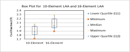
Figure 17. Box-and-whisker plots of LAAs.
Figure 18 showcases the identical plots for the EAA designs (8, 12, and 20 elements) generated using the SFO algorithm, with median CF values of 2.66, 2.81, and 2.95, respectively.

Figure 18. Box-and-whisker plots of EAAs.
Applying SFO in designing various EAA configurations reveals a broad variational scope in the cost function (CF). The 8-element EAA ranges from 2.53 to 2.89, while the 12- and 20-element EAAs exhibit ranges of 2.66 to 3.11 and 2.79 to 3.19, respectively. Thus, box-and-whisker plots for designing the LAA (10- and 16-element) and the EAA (8-, 12-, and 20-element) using the SFO technique offer robust and stable results.
Convergence Graphs of the SFO technique
These convergence graphs plot the iteration cycle’s lowest CF values. Figures 19 and 20 show the convergence plot for designing LAA and EAA, respectively.
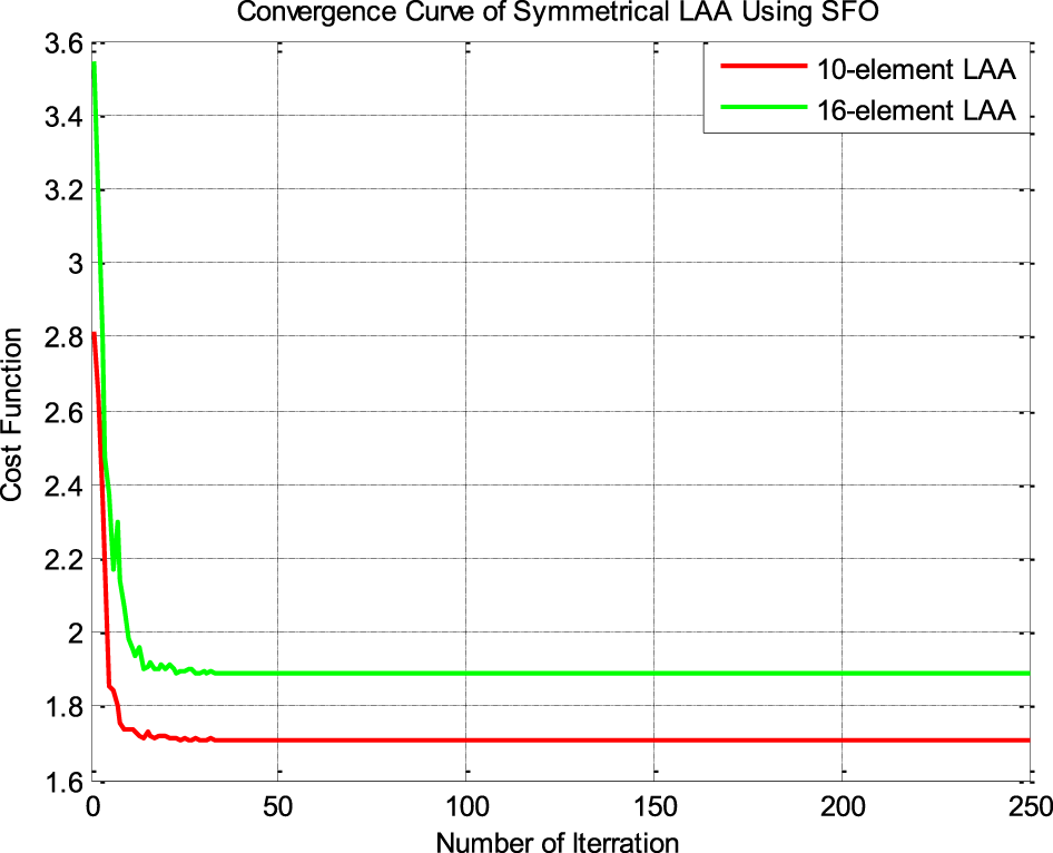
Figure 19. Convergence plots of LAAs.
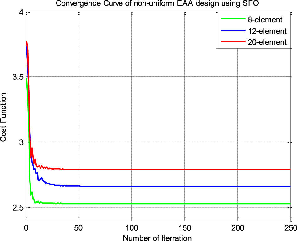
Figure 20. Convergence plots of EAAs.
The convergence curve of LAAs and EAAs approve the phenomenal performance of the SFO for stability and convergence speed.
Conclusion
The SFO algorithm is employed in this paper for designing the symmetrical LAA and EAA structure of dipole element with the non-uniform current excitation to each element of the array for applying in the 5G communication frequency at 3.5 GHz. The proposed approach using the SFO for designing the LAAs and EAAs shows an appreciable advancement in SLL reduction regarding the uniform array pattern and the methods proclaimed in the recently published articles. Thus, the numerical, statistical and EM field simulation-based results of SFO confirm that it can be an efficient optimizer for designing the LAA and EAA structures for 5G communication applications.
Acknowledgements
We thank SERB, DST, and the Government of India (Sanction Order No.: EEQ/2021/000700; dated 04 March 2022) for providing the funding necessary to pursue this research.
Competing interests
The authors affirm that there is no conflict of interest.

Rajrup Saha passed his B.Tech. in Electronics and Instrumentation Engineering from Bankura Unnayani Institute of Engineering, West Bengal, India, in 2013. He received his M.Tech. degree in Mechatronics from the Indian Institute of Engineering Science & Technology, Shibpur, in 2016. Currently, he is working as a full-time Ph.D. Research Scholar in the Electronics & Communication Engineering Department at the National Institute of Technology, Durgapur. His research interest includes the far-field radiation pattern synthesis of antenna array design using various evolutionary techniques

Avishek Das completed his B.E. degree in Electronics and Communication Engineering and M.Tech. (the project was done on Microwave at Antenna Division in SAMEER-Centre for Electromagnetics, Chennai) in ECE (Microwave) from The University of Burdwan, West Bengal, India in 2008 and 2010, respectively. He received an MBA in Human Resources from Sikkim Manipal University in 2014. He completed his Ph.D. in 2020 from the National Institute of Technology, Durgapur, West Bengal, India, under the Visvesvaraya Ph.D. Scheme for Electronics and IT, Ministry of Electronics and IT, Government of India. He was associated as a post-Ph.D. researcher at the National Institute of Technology, Durgapur, on the project funded by the Science and Engineering Research Board, Department of Science and Technology, Government of India (Grant No. EEQ/2017/000519, dated 23/03/2018). Presently, he is working as an Assistant Professor in the Department of Electronics and Communication Engineering, Haldia Institute of Technology, Haldia, West Bengal, India. His research interests include the application of evolutionary optimization techniques for the design of Antenna Arrays.

Durbadal Mandal earned B.E. degree in Electronics and Communication Engineering from Regional Engineering College, Durgapur, West Bengal, India, in 1996. He received the M.Tech. and Ph.D. degrees from the National Institute of Technology, Durgapur, West Bengal, India in 2008 and 2011, respectively. He works at the National Institute of Technology, Durgapur, West Bengal, India, as an Associate Professor in the Department of Electronics and Communication Engineering. His research interest includes Array Antenna design filter Optimization via Evolutionary Computing Techniques. He has published more than 350 research papers in International Journals and Conferences.

Rajib Kar earned a B.E. in Electronics and Communication Engineering from Regional Engineering College, Durgapur, West Bengal, India 2001. He received the M.Tech. and Ph.D. degrees from the National Institute of Technology, Durgapur, West Bengal, India, in 2008 and 2011, respectively. He works at the National Institute of Technology, Durgapur, West Bengal, India, as an Associate Professor in the Department of Electronics and Communication Engineering. His research interests include VLSI circuit optimization and signal processing using Evolutionary Computing Techniques. He has published more than 350 research papers in International Journals and Conferences.


