Impact statement
This research advances the sustainable use of naturally grown timber in the building industry, focusing on “organically grown” structures that leverage the natural growth patterns of irregularly shaped wood. Through advanced noninvasive scanning and computational models, this approach optimizes material usage, transforming overlooked wood forms into valuable resources for environmentally conscious building practices. Additionally, the study introduces a modular construction and simulation methodology that supports structural expansion and adaptability. This methodology aligns with the dual concepts of “growing”: effectively utilizing natural wood growth and developing scalable, modular construction techniques, as illustrated in Figure 1. These strategies ensure timber utilization is consistent with its inherent properties, promoting sustainable resource cycles and minimizing environmental impact.
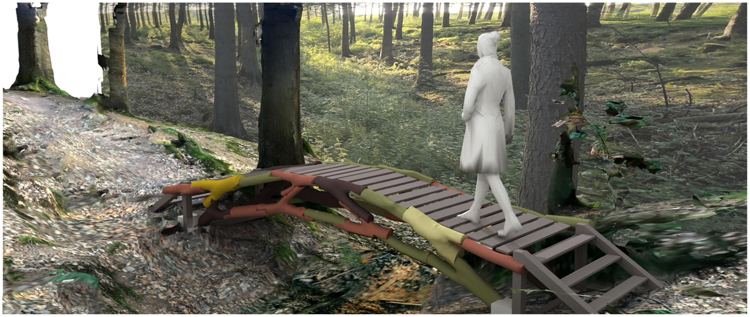
Figure 1. Bridge over a stream in the forest with onsite collected elements. Location: 50.683, 6.157.
Introduction
The concept of growth in construction emphasizes organic development, where materials adapt to and respond to external stimuli, and also involves leveraging these natural processes in a controlled manner to enhance the structural integrity and functionality of buildings.
Bio-based materials can expand across various microscales, influenced by the biological conditions of substance transport. This growth can often seem disorganized; however, recent advancements indicate promising rapid development. Applying these materials at meso- and macroscales poses a challenge in construction. Nonetheless, when combined and bound with other biomaterials, such as wood, they present potential opportunities (Saez et al. Reference Saez, Grizmann, Trautz and Werner2022).
In the context of load-bearing structures, grown trees and timber exhibit notable capacities due to their strength and lightness. This has been studied and demonstrated since the construction of the earliest primitive huts. However, the tree growth spans several generations. Growth guidance forms a significant branch within timber construction and finds applications here. Techniques for tree control, based on static study and load analysis, have been studied and implemented (Wessolly and Erb Reference Wessolly and Erb2014). This can be applied to the cultivation of mechanical elements, for their incorporation into grown wooden structures, or the cultivation of complete structures. Baubotanik – or living plant constructions – a term initiated by Ludwig (Reference Ludwig2012), serves as an example of this. It demonstrates how various experiments with tree growth patterns can be applied to architectural scale over the years (Bukauskas et al. Reference Bukauskas, Mayencourt, Shepherd, Sharma, Mueller, Walker and Bregulla2019).
If the properties of naturally grown timber are able to be measured and simulated, a broader and more efficient use of wood elements can be achieved. The hypothesis suggests that by strategically cultivating and guiding the growth of these tree patterns, construction methods can be developed that not only harness the inherent strengths of timber but also adapt organically to changing environmental conditions and structural demands. This approach has the potential to fundamentally transform timber utilization in construction, significantly enhancing its sustainability and adaptability.
Motivation
Wood has been extensively processed into boards, beams, slats and veneers, primarily using tree trunks and leaving branches and forks underutilized due to their small cross-sections and curves. The round wood collected, after processing, is approximately 50% preserved (Ramage et al. Reference Ramage, Burridge, Busse-Wicher, Fereday, Reynolds, Shah and Wu2017). This practice results in significant waste, as only about 30%–40% of the felled tree is used as building material – especially for deciduous trees – see Figure 2. The production of wood-based materials involves the extensive use of adhesives, often mixed with synthetic materials that may not be biodegradable. This process requires significant energy input due to the intensive level of processing involved. With the rising trend of using wood as a versatile and transformable material in architecture, there is a pressing need to enhance utilization efficiency in the timber industry to meet the increasing demand. This involves better utilization of the finite wood supply, including branches and other curved elements, in their original, round shape with minimal processing.
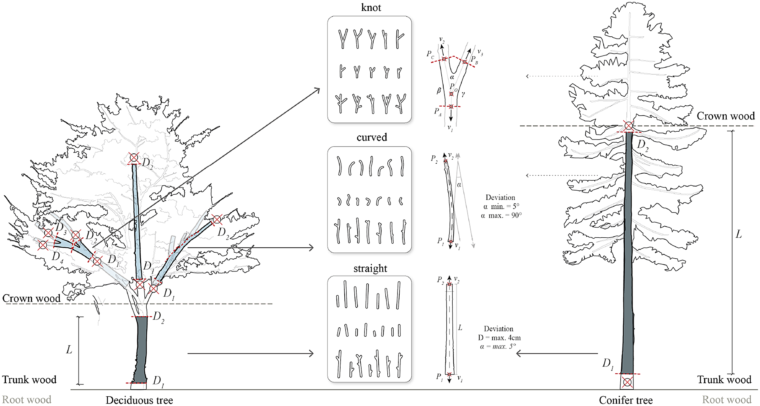
Figure 2. Segmentation of trees and their use for building materials: Straight segments, additionally curved elements and bifurcated elements (knots) (Wages, Reference Wages2022).
Each tree develops unique material characteristics due to its immediate environment. These traits are the results of natural optimization and economizing of the material due to static and dynamic loads (Mattheck Reference Mattheck1990; Mattheck Reference Mattheck1998). Innovative methodologies, including noninvasive scanning techniques, are currently being employed for the detailed investigation of individual material properties of naturally grown wood. These techniques, such as CT scanning, provide an in-depth analysis of the timber’s internal properties, including the detection of knots and the determination of fiber orientation (Huber et al. Reference Huber Johannes, Broman, Ekevad, Oja and Hansson2022; Tamke et al. Reference Tamke, Gatz, Svilans and Thomsen2021), thereby contributing significantly to our understanding of the material’s inherent characteristics. This data can help in the development of a better understanding of its material properties and in creating more efficient load-bearing structures. This interdisciplinary approach has the potential to unlock new possibilities in sustainable construction, leading to a more efficient use of resources.
Background
Wood analysis and its application in construction, specifically in Architecture, Engineering, and Construction, have been partially explored. Initially, methods for abstracting and simplifying tree growth for simulation were presented (Moreno Gata, Musto and Trautz Reference Moreno Gata, Musto, Trautz, Werner and Koering2020). Additionally, innovative digital technologies, including photogrammetry and laser scanning, have integrated natural and digital geometries, enhancing the design and manufacturing process in raw timber constructions. The works of Self and Vercruysse (Reference Self, Vercruysse, Menges, Sheil, Glynn and Skavara2017) and WholeTrees – Technology demonstrate the emerging potential in large-scale constructions. Concurrently, research on tree growth has produced geometrically unique, constructive elements (Amtsberg, Huang, Moreno Gata, et al. Reference Amtsberg, Moreno Gata, Huang, Marshall and Mueller2021; Vestartas, Reference Vestartas2021; Larsen and Aagaard Reference Larsen and Aagaard2020; Buelow et al. Reference Buelow, Oliyan, Mankouche and Vliet2018). Recent studies on raw timber (Desai Reference Desai2020) and smaller-diameter “green oak” wood (Hofmann et al. Reference Hofmann, Brüchert, Sauter Udo, Schober, Hörnel-Metzger and Müller2023), utilizing material characterization and loading tests, are initial attempts to ascertain the load-bearing capacities within technical structures.
Methodology
Data collection with noninvasive and image-based methods for geometry and material analysis
The first aim of this work is to systematically document and comprehend the intrinsic properties of naturally grown timber, with the ultimate goal of creating a model applicable to the evaluation and design of future structural elements.
The acquisition of tree geometry employs advanced methods such as photogrammetry and 3D scanning, as showcased in Figure 3. In subsequent stages, noninvasive data sampling techniques, specifically X-ray CT and magnetic resonance imaging (MRI), have been extensively employed to analyze plant growth, particularly concerning reaction wood and root structures (Brereton et al. Reference Brereton, Ahmed, Sykes, Ray, Shield, Karp and Murphy2015; Pflugfelder et al. Reference Pflugfelder, Metzner, Chlubek, Koller, Bühler, Auke, Jahnke, Kochs and van Dusschoten2015). These noninvasive modalities, grounded in different physical principles, present unique potentials and challenges. In this context, CT, with its capability to analyze density variations within wood specimens, is utilized.
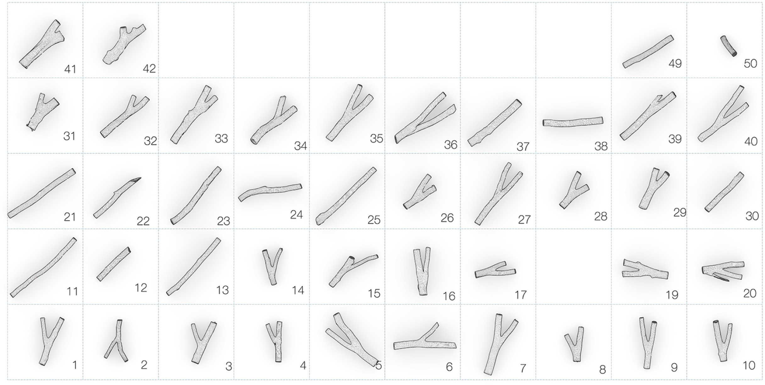
Figure 3. Dataset of naturally grown elements based on 3D laser scanning and photogrammetry.
CT methods, along with various information types and calibration methodologies, facilitate the detailed acquisition of density variations. Observing density gradients along plant growth in three dimensions reveals variations from the center to the bark. Post-processing of this information, coupled with CT generation, enables further slicing to investigate specific areas, seamlessly integrating into future workflows, particularly those focused on material modeling.
The integration of this information, in tandem with standard superficial 3D laser scanning methods, is feasible, as illustrated in Figure 4. The geometric acquisition is further integrated into a non-uniform rational B-spline (NURBS) superficial geometrical model. This model, augmented by CT images, provides crucial growth parameters, including rings, thereby unveiling both geometric and material properties.
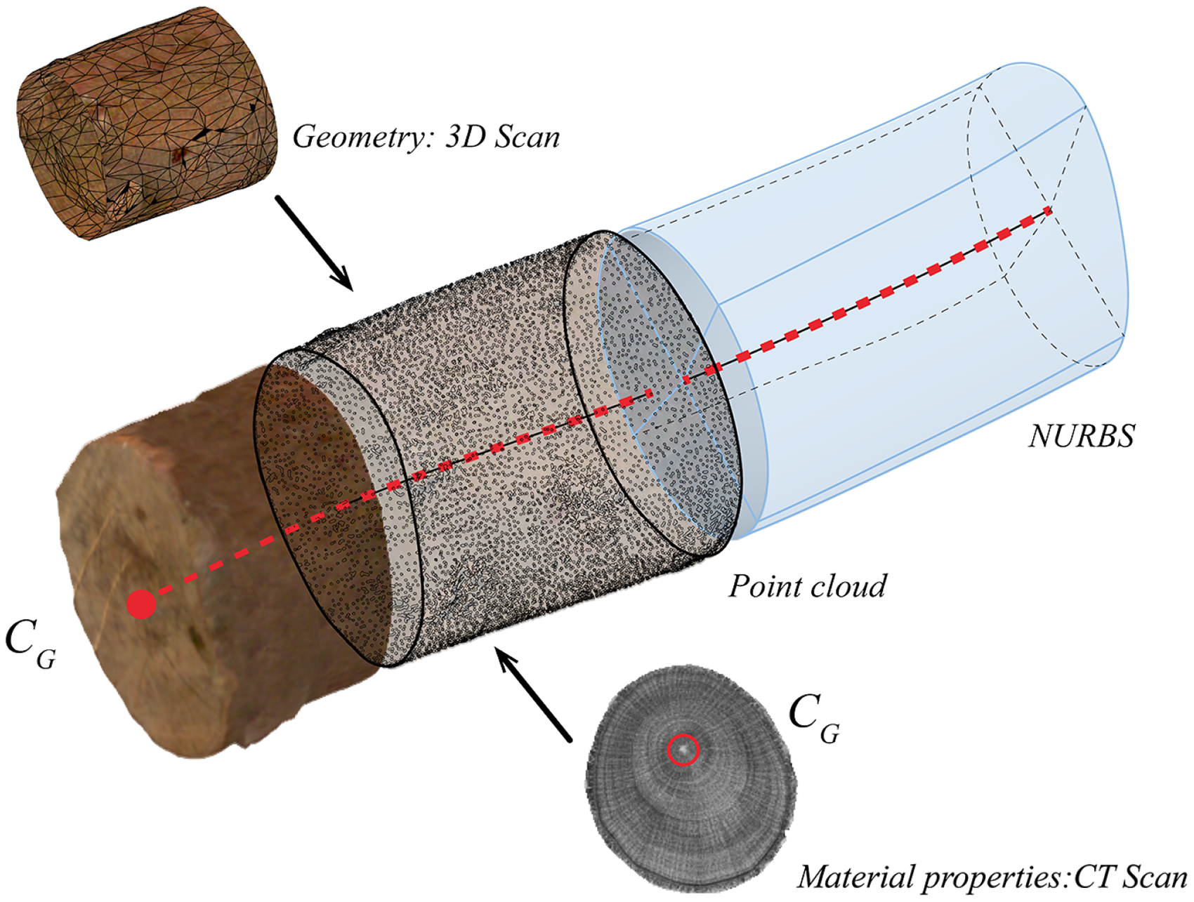
Figure 4. Development of a combined geometric and material model analysis environment based on surface images and tomographic computer scans. Center line (in red) along the volume and generation of a NURBS model.
Development and construction of a geometric model
Generic model
The geometric construction of the model, based on previous documentation or scans, results in a general geometrical model. This process yields a discrete surface approximation of the specimens analyzed previously.
The pathway unfolds as follows: it starts with the importation of an image-based model, re-positioned according to Moreno Gata, Seiter, et al. (Reference Moreno Gata, Seiter, Grizmann and Trautz2023). The mesh volume is subdivided into transverse sections parallel to the relocation plane
![]() ${\alpha _i}$
, defined by the vertical vector
${\alpha _i}$
, defined by the vertical vector
![]() $h$
and the normal vector
$h$
and the normal vector
![]() ${a_i}$
. This generates a section
${a_i}$
. This generates a section
![]() ${s_i}$
, determining a geometric center point
${s_i}$
, determining a geometric center point
![]() ${A_i}$
, later generalized as uppercase
${A_i}$
, later generalized as uppercase
![]() ${C_g}$
. This process constructs a geometric center line
${C_g}$
. This process constructs a geometric center line
![]() ${c_g}$
, composed of the individual geometric centers.
${c_g}$
, composed of the individual geometric centers.
Subsequently, this information is hierarchically organized for NURBS construction. Given the cross-sections
![]() ${s_i}$
, they are divided into a maximum of four points
${s_i}$
, they are divided into a maximum of four points
![]() ${S_i}$
. These points segment the sections, later used to construct a degree-3 transition surface. These 2D surfaces, termed patches, along with the geometric center line, are exported for subsequent mechanical simulations, see Figure 5.
${S_i}$
. These points segment the sections, later used to construct a degree-3 transition surface. These 2D surfaces, termed patches, along with the geometric center line, are exported for subsequent mechanical simulations, see Figure 5.
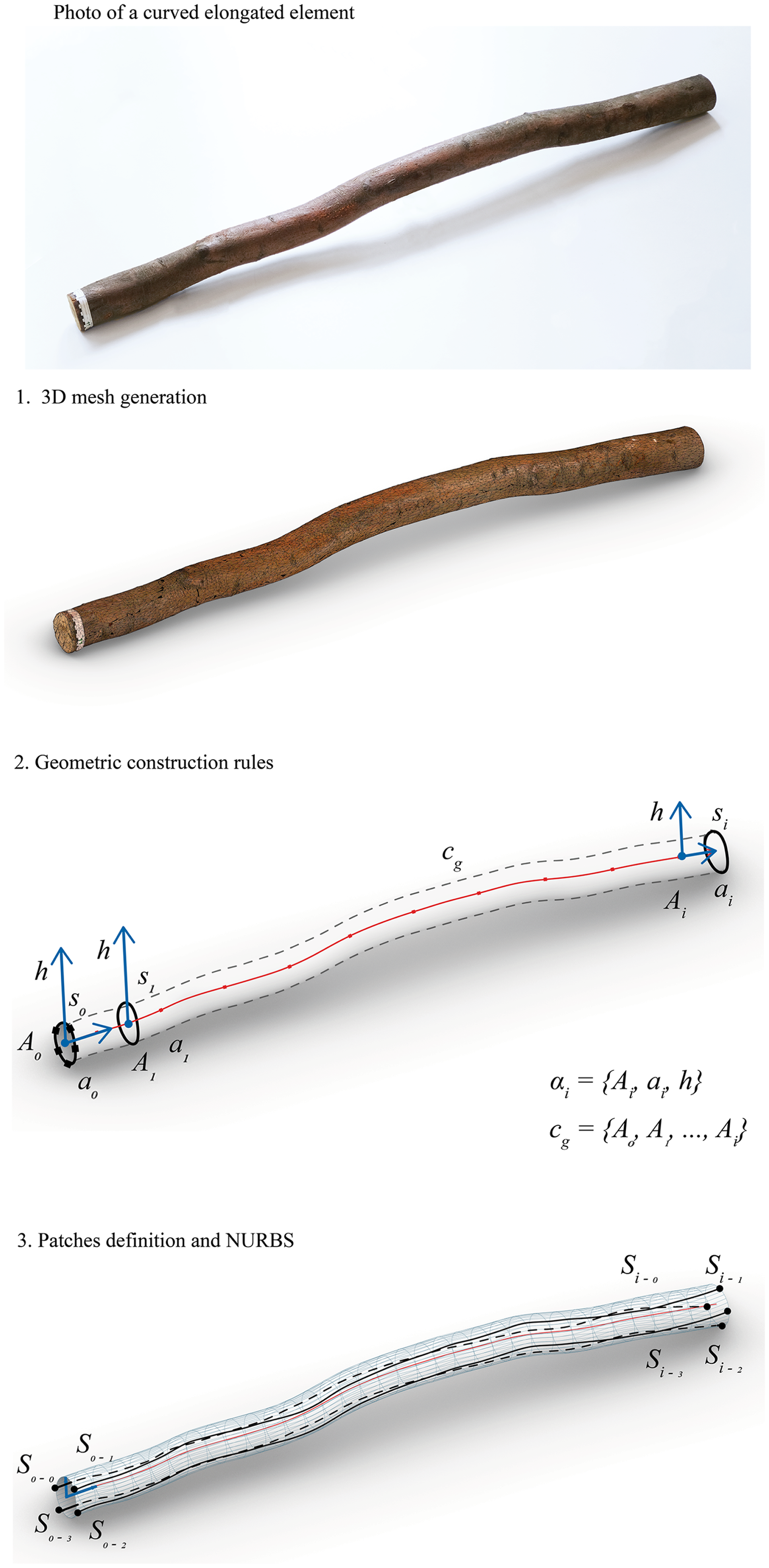
Figure 5. Pathway for the geometric construction of a generic elongated curved element.
Generic model for bifurcations
The digital processing of bifurcated elements, or forks, is determined by an integration in three axes of the generic model (Figure 6). The oriented model, in 3D mesh format, interprets a bifurcation with three central lines,
![]() $a$
,
$a$
,
![]() $b$
and
$b$
and
![]() $c$
, which are discretized in their length, yielding vectors
$c$
, which are discretized in their length, yielding vectors
![]() ${a_0}$
,
${a_0}$
,
![]() ${b_0}$
and
${b_0}$
and
![]() ${c_0}$
at their initial segment starting from the bifurcation. This process allows the generation of sections
${c_0}$
at their initial segment starting from the bifurcation. This process allows the generation of sections
![]() ${s_{A - 0}}$
,
${s_{A - 0}}$
,
![]() ${s_{B - 0}}$
and
${s_{B - 0}}$
and
![]() ${s_{C - 0}}$
, whose centroids (
${s_{C - 0}}$
, whose centroids (
![]() ${A_0},{B_0},{C_0}$
) define the plane
${A_0},{B_0},{C_0}$
) define the plane
![]() $\pi $
. This plane
$\pi $
. This plane
![]() $\pi $
have a normal vector
$\pi $
have a normal vector
![]() ${h_\pi }$
. The sum of possible combinations of vectors
${h_\pi }$
. The sum of possible combinations of vectors
![]() ${a_0}$
,
${a_0}$
,
![]() ${b_0}$
and
${b_0}$
and
![]() ${c_0}$
, along with the vector
${c_0}$
, along with the vector
![]() $h$
, and the central geometric point
$h$
, and the central geometric point
![]() ${C_{g - 0}}$
, gives us the cutting planes
${C_{g - 0}}$
, gives us the cutting planes
![]() $\alpha, \beta, \gamma $
. These planes intersect the volume of the 3D mesh.
$\alpha, \beta, \gamma $
. These planes intersect the volume of the 3D mesh.
The subsequent step of defining patches and constructing NURBS is determined, similar to the generic model, by the division of cross-sections
![]() ${s_i}$
, in this case coinciding with the edges defined by the cutting planes. For a proper curvature transition, a subdivision geometry element (Sub-D) is employed. This is followed by exporting for subsequent mechanical simulation.
${s_i}$
, in this case coinciding with the edges defined by the cutting planes. For a proper curvature transition, a subdivision geometry element (Sub-D) is employed. This is followed by exporting for subsequent mechanical simulation.
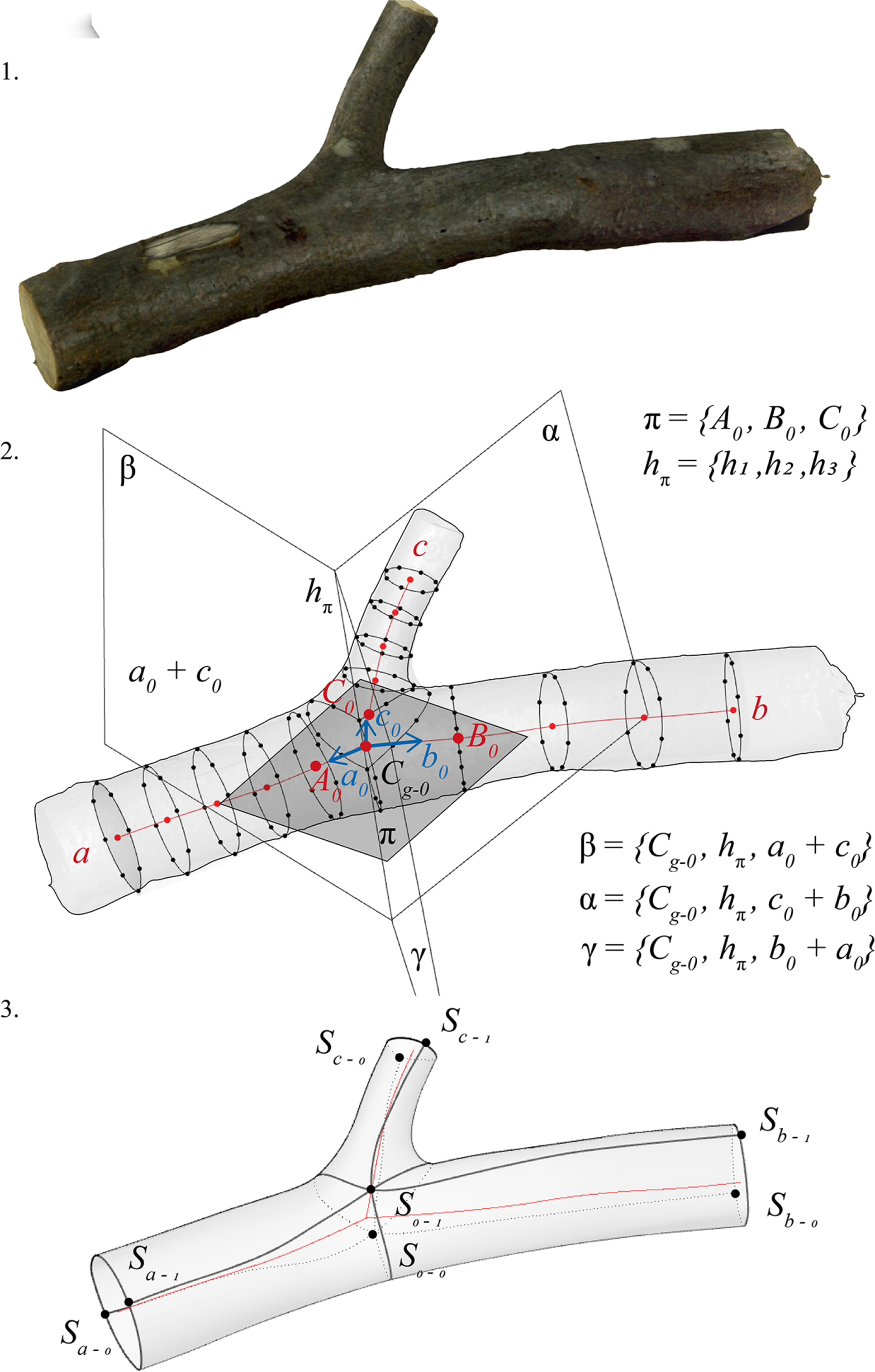
Figure 6. Geometric construction of a tree bifurcation based on subdivision modeling.
This geometric process is integrated and programmed within the Rhinoceros (McNeel et al. Reference McNeel2023) environment to facilitate its automation.
Growth-induced material properties
The distribution of biomass material within a tree exhibits a polar pattern influenced by its natural growth. Understanding and accurately representing this distribution is crucial for creating comprehensive mechanical models, especially for raw timber elements. The described methodology involves calibrating 3D-scanned components by aligning system axes with volume distribution obtained from CT scans. This calibration ensures an authentic representation, capturing complete spatial dimensions and effective spatial axes. This results in an enriched model with superficial two-dimensional representation and internal information. It allows for preliminary studies on the implications of asymmetry in curved and bifurcated grown elements. To comprehensively analyze trees, it would be necessary to supplement the work with information from sources, such as MRI or data with varying water content.
Polar definition of the cross-section
A significant challenge in this context is accurately determining the center line, also known as the growth central axis, often mistakenly assumed to be the geometric central axis. This center line is formed by the union of growth centers
![]() ${C_G}$
, currently only obtainable through visual information or CT data. The center
${C_G}$
, currently only obtainable through visual information or CT data. The center
![]() ${C_G}$
represents the tree’s initial growth center, located at the central point of the annual rings. In a straight element with a circular cross-section, the geometric centroids
${C_G}$
represents the tree’s initial growth center, located at the central point of the annual rings. In a straight element with a circular cross-section, the geometric centroids
![]() ${C_g}$
and growth centers
${C_g}$
and growth centers
![]() ${C_G}$
tend to coincide. However, this deviation becomes more pronounced in irregular elements, such as oval-shaped cross-sections primarily generated by reaction wood or in a bifurcation. This is supplemented with the center of mass, –
${C_G}$
tend to coincide. However, this deviation becomes more pronounced in irregular elements, such as oval-shaped cross-sections primarily generated by reaction wood or in a bifurcation. This is supplemented with the center of mass, –
![]() ${C_M}$
–. This is the sum of all masses within the section. In a rectilinear element, it tends to be the same as
${C_M}$
–. This is the sum of all masses within the section. In a rectilinear element, it tends to be the same as
![]() ${C_G}$
and
${C_G}$
and
![]() ${C_g}$
. To determine its location in an irregular element, it is necessary to conduct a density variation study. This center allows observing the displacement of biomass throughout growth. This is applied to analyze eccentricities and displacement of the centers along the tree length, see Figure 7.
${C_g}$
. To determine its location in an irregular element, it is necessary to conduct a density variation study. This center allows observing the displacement of biomass throughout growth. This is applied to analyze eccentricities and displacement of the centers along the tree length, see Figure 7.
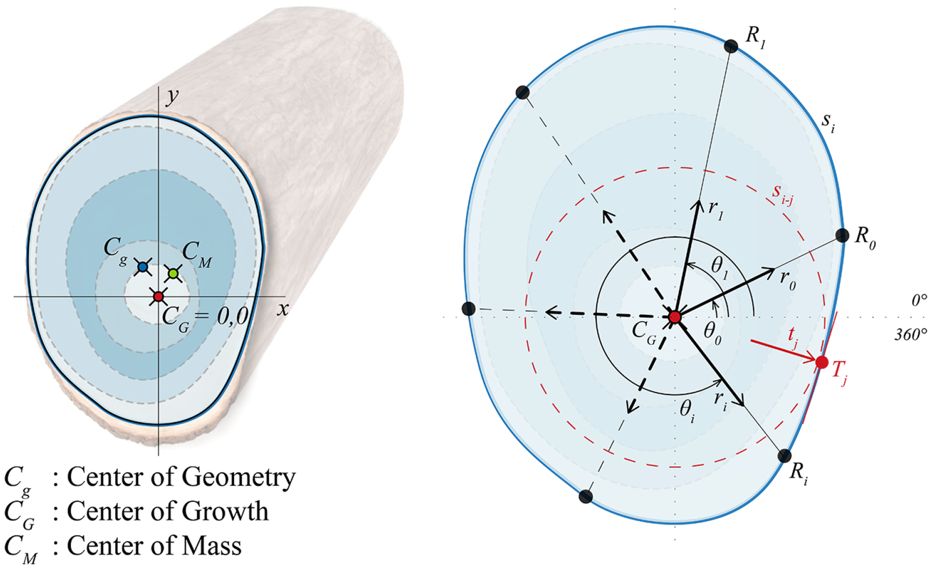
Figure 7. Definition of the three centers of the cross-section: geometric center –centroid–, growth center and center of mass. Polar ray (r) positioning for cross-section analysis.
Wood cross-sections are commonly considered with a polar coordinate system. The center
![]() ${C_G}$
, serving as the center of the polar system, acts as the starting point for drawing rays
${C_G}$
, serving as the center of the polar system, acts as the starting point for drawing rays
![]() ${r_i}$
extending to the previously defined geometric perimeter
${r_i}$
extending to the previously defined geometric perimeter
![]() ${s_i}$
. Rays are determined at an angle
${s_i}$
. Rays are determined at an angle
![]() ${\theta _i}$
. The intersection of
${\theta _i}$
. The intersection of
![]() ${r_i}$
with
${r_i}$
with
![]() ${s_i}$
gives us the points
${s_i}$
gives us the points
![]() ${R_i}$
. These rays are utilized for a density variation analysis later in Figure 9.
${R_i}$
. These rays are utilized for a density variation analysis later in Figure 9.
Growth-induced mass displacements
The mass displacement can be observed in the model (see Figure 8). For visualization, a tubular volume with variable radius
![]() $\left| {{{\bf{t}}_{\bf{j}}}} \right|$
is traced along the central growth line as a reference. This tube is determined at each cross-section, taking the smallest modulus of all
$\left| {{{\bf{t}}_{\bf{j}}}} \right|$
is traced along the central growth line as a reference. This tube is determined at each cross-section, taking the smallest modulus of all
![]() $\left| {{{\bf{r}}_{\bf{i}}}} \right|$
. This defines a circle
$\left| {{{\bf{r}}_{\bf{i}}}} \right|$
. This defines a circle
![]() ${s_{i - j}}$
, with a tangent
${s_{i - j}}$
, with a tangent
![]() ${T_j}$
at
${T_j}$
at
![]() ${s_i}$
. Using this method, it is possible to visualize an approximation of the volume generated by the tree as reaction wood. In the example in Figure 8 – based on a reference oak specimen – it can be recognized how the added volume in growth corresponds to tension wood. Furthermore, one central line of a bifurcation element has been extracted. With the
${s_i}$
. Using this method, it is possible to visualize an approximation of the volume generated by the tree as reaction wood. In the example in Figure 8 – based on a reference oak specimen – it can be recognized how the added volume in growth corresponds to tension wood. Furthermore, one central line of a bifurcation element has been extracted. With the
![]() ${C_G}$
of each section in a straight line, one can observe the quantitative difference in geometric eccentricities, which increase along with the tension in the wood.
${C_G}$
of each section in a straight line, one can observe the quantitative difference in geometric eccentricities, which increase along with the tension in the wood.
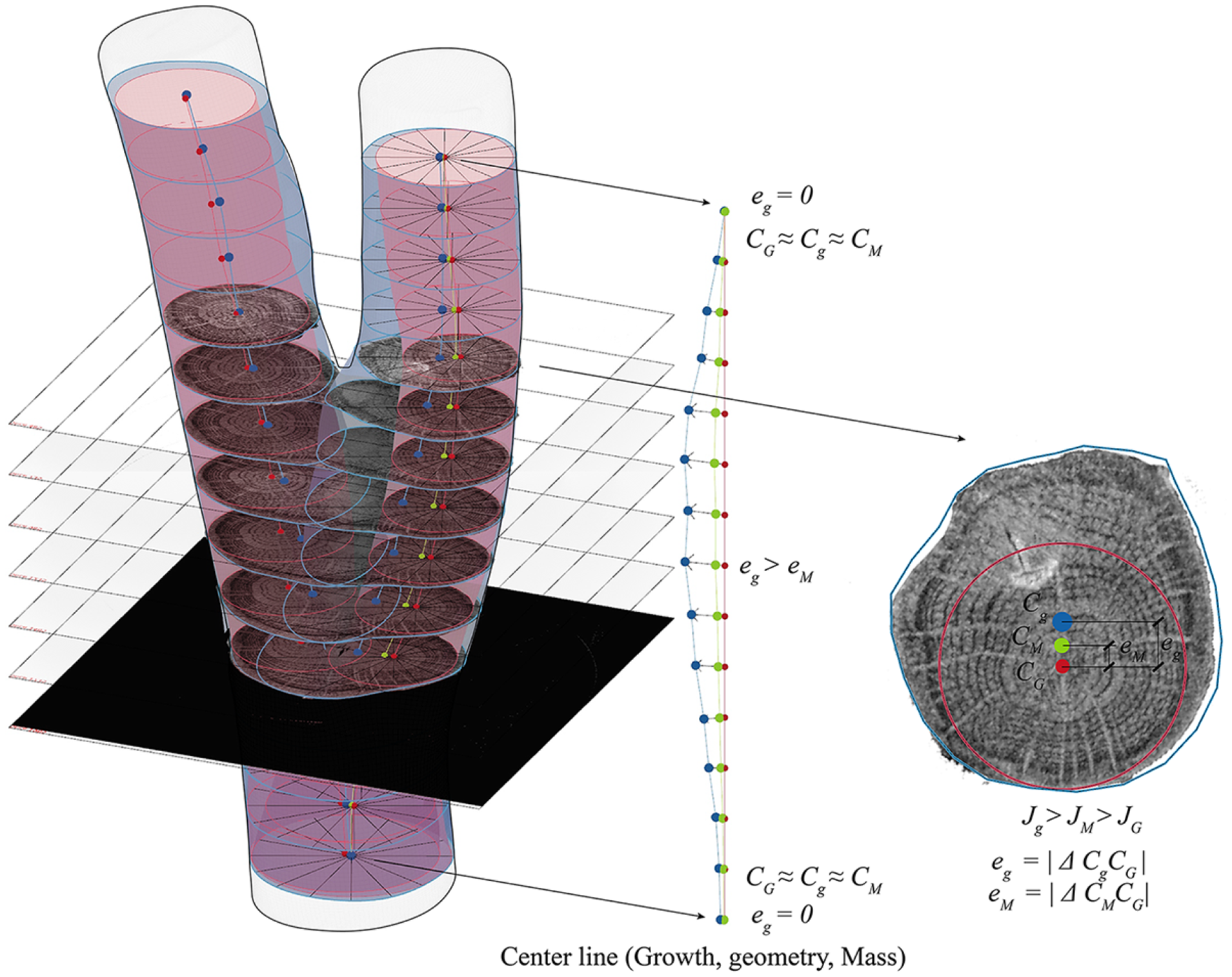
Figure 8. Visualization of the bifurcation of a small specimen of oak. In red: reference tangent circular geometry with
![]() ${C_G}$
, if the tree grows straight. In blue: grown geometry with eccentric displacement of
${C_G}$
, if the tree grows straight. In blue: grown geometry with eccentric displacement of
![]() ${C_g}$
. The production of tension wood can be seen in blue.
${C_g}$
. The production of tension wood can be seen in blue.
![]() ${C_M}$
calculated after applying the derived polynomial density.
${C_M}$
calculated after applying the derived polynomial density.
The last part of this section outlines the application of the polar method for analyzing density variations within the volume. These techniques are instrumental in detecting higher-density zones, such as heartwood. The relevant eccentricities are then defined. The eccentricity
![]() ${e_g}$
of the central axis is calculated as the distance between
${e_g}$
of the central axis is calculated as the distance between
![]() ${C_g}$
and
${C_g}$
and
![]() ${C_G}$
. After calculating the
${C_G}$
. After calculating the
![]() ${C_M}$
, with the help of the density distribution (in Figure 9), the
${C_M}$
, with the help of the density distribution (in Figure 9), the
![]() ${e_M}$
can be found. This is relevant for a mechanical understanding of the tree, as it has implications on the moment of inertia of each section
${e_M}$
can be found. This is relevant for a mechanical understanding of the tree, as it has implications on the moment of inertia of each section
![]() ${s_i}$
. In Figure 8, the cross-section on the right illustrates the variation in moment of inertia due to geometrical
${s_i}$
. In Figure 8, the cross-section on the right illustrates the variation in moment of inertia due to geometrical
![]() ${J_g}$
, in comparison to a moment of inertia reference due to growth
${J_g}$
, in comparison to a moment of inertia reference due to growth
![]() ${J_G}$
. For instance, in a straight-grown tree with a perimeter
${J_G}$
. For instance, in a straight-grown tree with a perimeter
![]() ${s_{i - j}}$
– delineated in red – its
${s_{i - j}}$
– delineated in red – its
![]() ${J_G}$
would be much lower than the actual
${J_G}$
would be much lower than the actual
![]() ${J_g}$
. This consideration requires complementing with a calculation of the mass moment of inertia
${J_g}$
. This consideration requires complementing with a calculation of the mass moment of inertia
![]() ${J_M}$
.
${J_M}$
.
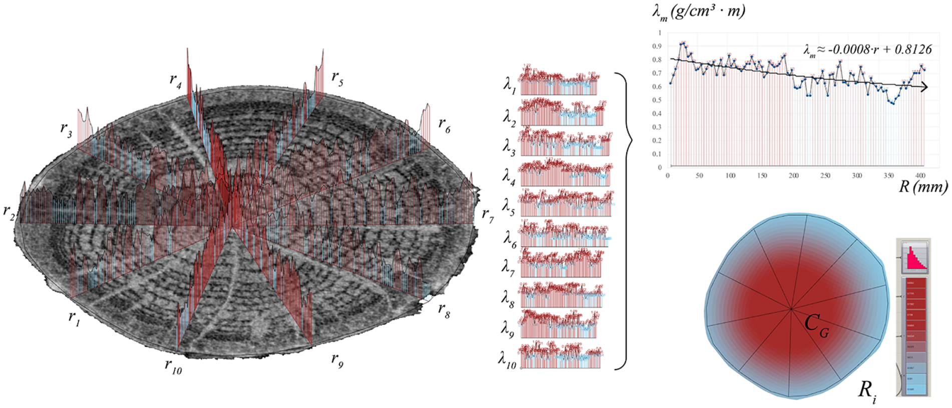
Figure 9. Material density variation
![]() $\lambda $
along the radius
$\lambda $
along the radius
![]() $R$
.
$R$
.
![]() ${\lambda _i}$
corresponds to every
${\lambda _i}$
corresponds to every
![]() ${r_i}$
, and
${r_i}$
, and
![]() ${\lambda _m}$
represents the resulting density in the cross-section. Using a polynomial, a formula can be derived, which can then be reapplied to the cross-section from
${\lambda _m}$
represents the resulting density in the cross-section. Using a polynomial, a formula can be derived, which can then be reapplied to the cross-section from
![]() ${C_G}$
to
${C_G}$
to
![]() ${R_i}$
.
${R_i}$
.
Exploration of material stiffness
The polar structure has been used to determine the moments of inertia and densities, as discussed above. In addition, there are more properties that vary along the radius, starting from
![]() ${C_G}$
, such as strength and stiffness. Studies have shown that there is a relationship between density variation and strength. Matsuo-Ueda et al. (Reference Matsuo-Ueda, Tsunezumi, Jiang, Yoshida, Yamashita, Matsuda, Matsumura, Ikami and Yamamoto2022) show that in Japanese cedar – softwood, its modulus is higher in the center and decreases in the radial direction (see Figure 10), right; on the contrary, in deciduous trees – hardwood, their modulus is lower in the center and increases in the radial direction, which can be contrasted with the density variation study of the previous section. The integration of material properties and the
${C_G}$
, such as strength and stiffness. Studies have shown that there is a relationship between density variation and strength. Matsuo-Ueda et al. (Reference Matsuo-Ueda, Tsunezumi, Jiang, Yoshida, Yamashita, Matsuda, Matsumura, Ikami and Yamamoto2022) show that in Japanese cedar – softwood, its modulus is higher in the center and decreases in the radial direction (see Figure 10), right; on the contrary, in deciduous trees – hardwood, their modulus is lower in the center and increases in the radial direction, which can be contrasted with the density variation study of the previous section. The integration of material properties and the
![]() $E$
modulus, based on material tests, can be employed for further analytical methods and simulations. In Figure 10, a general formulation of area distribution proposes how to numerically analyze the variation of stiffness and the inertia moment
$E$
modulus, based on material tests, can be employed for further analytical methods and simulations. In Figure 10, a general formulation of area distribution proposes how to numerically analyze the variation of stiffness and the inertia moment
![]() $J$
along the radius, where
$J$
along the radius, where
![]() ${A_i}$
is the area of every accumulation of growth rings,
${A_i}$
is the area of every accumulation of growth rings,
![]() ${J_i}$
the moment of inertia and
${J_i}$
the moment of inertia and
![]() ${E_i}$
the Young modulus.
${E_i}$
the Young modulus.
 $$\matrix{ {{A_{{\rm{tot}}}}} \hfill & { = {A_0}{{{E_0}} \over {{E_{{\rm{tot}}}}}} + {A_1}{{{E_1}} \over {{E_{{\rm{tot}}}}}} + \ldots + {A_i}{{{E_i}} \over {{E_{{\rm{tot}}}}}}} \hfill & { = \mathop \sum \limits_{n = 0}^{n = i} {A_i}{{{E_i}} \over {{E_{{\rm{tot}}}}}}} \hfill \cr {{J_{{\rm{tot}}}}} \hfill & { = {J_0}{{{E_0}} \over {{E_{{\rm{tot}}}}}} + {J_1}{{{E_1}} \over {{E_{{\rm{tot}}}}}} + \ldots + {J_i}{{{E_i}} \over {{E_{{\rm{tot}}}}}}} \hfill & { = \mathop \sum \limits_{n = 0}^{n = i} {J_i}{{{E_i}} \over {{E_{{\rm{tot}}}}}}} \hfill \cr } $$
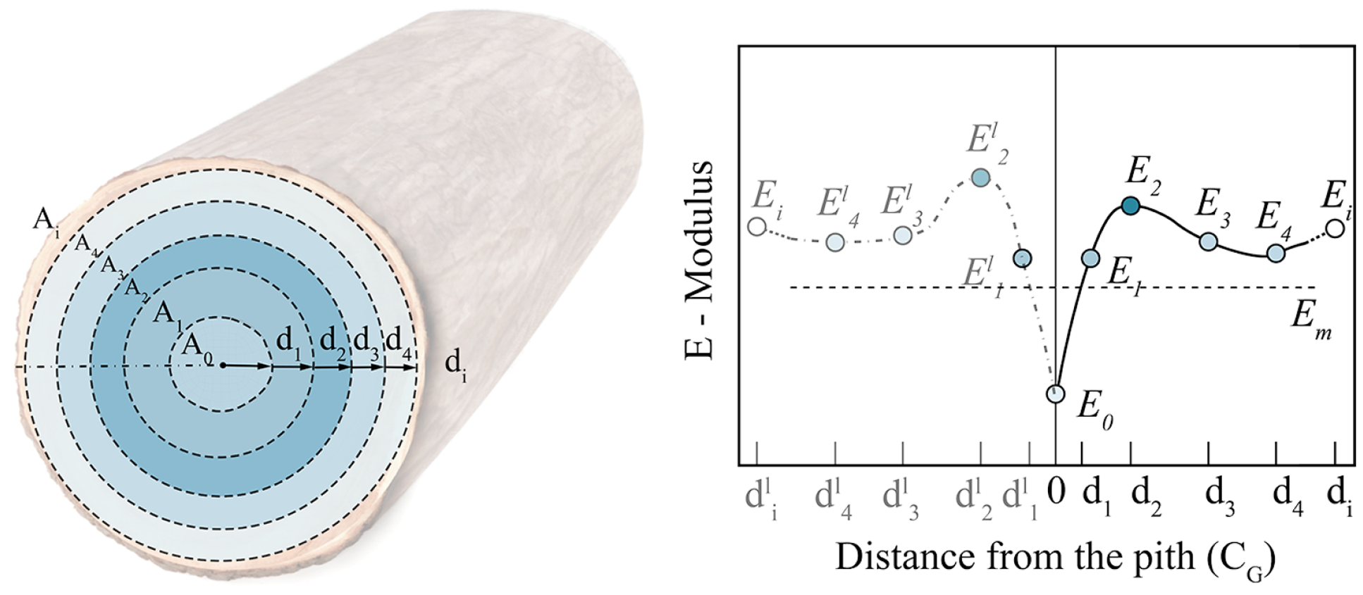
Figure 10. Symmetrized variation of the E-modulus over the cross-section according to Matsuo-Ueda et al. Reference Matsuo-Ueda, Tsunezumi, Jiang, Yoshida, Yamashita, Matsuda, Matsumura, Ikami and Yamamoto2022, in a softwood.
Isogeometric analysis
Geometries in engineering design applications are typically modeled in CAD software by NURBS. As Hughes, Cottrell and Bazilevs (Reference Hughes, Cottrell and Bazilevs2005) initially demonstrated, these geometry-describing functions can be used in the isogeometric analysis to solve engineering problems. In contrast to classical simulation approaches, such as finite element analysis (FEA), the computational effort of meshing the geometry can be neglected. Many efficient and numerically stable algorithms exist for processing NURBS in NURBS objects. Besides its usefulness in accurately describing conical cross-sections such as ellipsoids, circles, spheres or cylinders, the significant advantage of the FEA is the higher continuity over element borders and the efficient mesh refinement possibilities. As stated in the previous chapter, through modern 3D-scanning techniques, an accurate description of arbitrary geometries is possible. Here, a two-dimensional NURBS surface patch in a three-dimensional space is created. Coming from 2D image data, a solid volume description can be generated by scaling the NURBS surface in a scaling center point. This method is called scaled boundary isogeometric analysis (SBIGA) (Chen, Simeon and Klinkel Reference Chen, Simeon and Klinkel2016, Chasapi et al. Reference Chasapi, Mester, Simeon and Klinkel2022). For the application in modeling long slender geometries, such as wooden branches or trees, this technique has drawbacks since numerical condition problems due to obtuse-angled polyhedral patches can occur. To avoid this, a novel generalized scaled boundary isogeometric analysis (GSBIGA) approach is introduced. This new method employs a scaling center line instead of a scaling center point (Spahn et al., Reference Spahn, Moreno Gata, Trautz and Klinkel2024). Figure 11 shows the basic principles.

Figure 11. General SBIGA approach depicted, spanned by parametric coordinates
![]() $\xi $
,
$\xi $
,
![]() $\eta $
and
$\eta $
and
![]() $\zeta $
. Functions as polar scaling approach in cross-sectional area for
$\zeta $
. Functions as polar scaling approach in cross-sectional area for
![]() $\xi $
and
$\xi $
and
![]() $\eta $
at a given
$\eta $
at a given
![]() $\zeta $
.
$\zeta $
.
For this purpose, the parameters
![]() $\eta $
,
$\eta $
,
![]() $\zeta $
and
$\zeta $
and
![]() $\xi $
are introduced. The boundary surface is spanned by
$\xi $
are introduced. The boundary surface is spanned by
![]() $\eta $
in tangential and
$\eta $
in tangential and
![]() $\zeta $
in the longitudinal direction; the spatial scaling direction is described by
$\zeta $
in the longitudinal direction; the spatial scaling direction is described by
![]() $\xi $
. All three parameters are defined on the interval from
$\xi $
. All three parameters are defined on the interval from
![]() $0$
$0$
![]() $ \le $
$ \le $
![]() $\eta $
,
$\eta $
,
![]() $\zeta $
,
$\zeta $
,
![]() $\xi $
$\xi $
![]() $ \le 1$
. The modeled slender geometry of the domain
$ \le 1$
. The modeled slender geometry of the domain
![]() ${{\rm{\Omega }}_0}$
has a defined longitudinal direction, coinciding with the primary growth direction of wood and its center line. This modeling technique shares the characteristics of wood as the polar definition in the cross-sectional area. This relation is advantageous for modeling the polar dependency of material properties as already suggested in Figure 7. The position vector
${{\rm{\Omega }}_0}$
has a defined longitudinal direction, coinciding with the primary growth direction of wood and its center line. This modeling technique shares the characteristics of wood as the polar definition in the cross-sectional area. This relation is advantageous for modeling the polar dependency of material properties as already suggested in Figure 7. The position vector
![]() $\hat X\left( \zeta \right)$
contains the Cartesian coordinates of an arbitrary point on the center line
$\hat X\left( \zeta \right)$
contains the Cartesian coordinates of an arbitrary point on the center line
![]() $\left( {{{\hat X}_1},{\rm{\;}}{{\hat X}_2},{\rm{\;}}{{\hat X}_3}} \right)$
, also known as the center of growth
$\left( {{{\hat X}_1},{\rm{\;}}{{\hat X}_2},{\rm{\;}}{{\hat X}_3}} \right)$
, also known as the center of growth
![]() ${C_G}$
. A point on the boundary surface
${C_G}$
. A point on the boundary surface
![]() $\left( {{{\tilde X}_1},{\rm{\;}}{{\tilde X}_2},{\rm{\;}}{{\tilde X}_3}} \right)$
is described by the position vector
$\left( {{{\tilde X}_1},{\rm{\;}}{{\tilde X}_2},{\rm{\;}}{{\tilde X}_3}} \right)$
is described by the position vector
![]() $\tilde X$
, while the position vector
$\tilde X$
, while the position vector
![]() $X$
describes an arbitrary point
$X$
describes an arbitrary point
![]() $\left( {{X_1},{\rm{\;}}{X_2},{\rm{\;}}{X_3}} \right)$
in the interior of the domain. For an arbitrary point on the boundary
$\left( {{X_1},{\rm{\;}}{X_2},{\rm{\;}}{X_3}} \right)$
in the interior of the domain. For an arbitrary point on the boundary
![]() $\partial {{\rm{\Omega }}_0},$
the following relation exists
$\partial {{\rm{\Omega }}_0},$
the following relation exists
Here,
![]() ${X_s}$
contains all control point coordinates of the boundary surface and
${X_s}$
contains all control point coordinates of the boundary surface and
![]() ${N_b}\left( {\eta, {\rm{\;}}\zeta } \right)$
the corresponding NURBS basis functions.
${N_b}\left( {\eta, {\rm{\;}}\zeta } \right)$
the corresponding NURBS basis functions.
Any point on the center line can be expressed by
with the location vector
![]() ${X_0}$
containing the coordinates of all control points of the center line. An arbitrary point in the interior domain of the geometry
${X_0}$
containing the coordinates of all control points of the center line. An arbitrary point in the interior domain of the geometry
![]() ${{\rm{\Omega }}_0}$
can be expressed by
${{\rm{\Omega }}_0}$
can be expressed by
In contrast to the SBIGA, for the novel GSBIGA, the center line needs to be described with the same NURBS basis functions as the boundary patches in the longitudinal direction. This is depicted in Figure 12, with
![]() $R_i^p$
and
$R_i^p$
and
![]() $R_j^q$
being the NURBS boundary functions and
$R_j^q$
being the NURBS boundary functions and
![]() $R_k^r$
being the NURBS functions in scaling direction. In the longitudinal direction, share the boundary and the center line the same NURBS basis functions
$R_k^r$
being the NURBS functions in scaling direction. In the longitudinal direction, share the boundary and the center line the same NURBS basis functions
![]() $R_j^q$
. The general concept of the scaled boundary method remains unchanged. The 3D scanned geometric model, including the NURBS description of the body, is directly used to analyze the structure. Since isogeometric analysis is used, mesh refinement is straightforward by applying the aforementioned refinement methods. The center line should represent the initial annual ring (pith). The shape of a tree’s pith, or growth center 7, is individual as its shape and strongly depends on wood type and constraints such as light, soil or altitude. The shape of the center line and position can be arbitrarily chosen to match these obligations. Thus, the shape of the boundary surface and the shape of the center line are generally independent. The only prerequisites are the center line position in the geometries interior domain and using similar basis functions to the longitudinal boundary patches.
$R_j^q$
. The general concept of the scaled boundary method remains unchanged. The 3D scanned geometric model, including the NURBS description of the body, is directly used to analyze the structure. Since isogeometric analysis is used, mesh refinement is straightforward by applying the aforementioned refinement methods. The center line should represent the initial annual ring (pith). The shape of a tree’s pith, or growth center 7, is individual as its shape and strongly depends on wood type and constraints such as light, soil or altitude. The shape of the center line and position can be arbitrarily chosen to match these obligations. Thus, the shape of the boundary surface and the shape of the center line are generally independent. The only prerequisites are the center line position in the geometries interior domain and using similar basis functions to the longitudinal boundary patches.
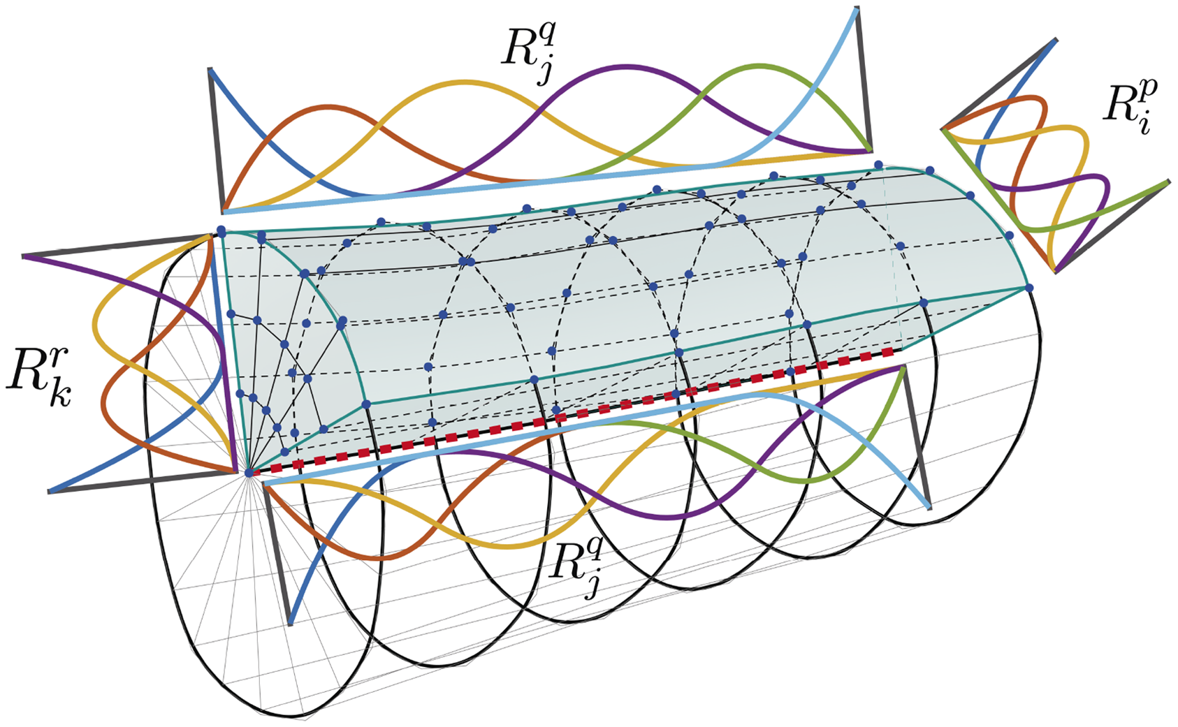
Figure 12. Geometry patch and its NURBS functions. Boundary surface spanned by
![]() $R_j^q$
and
$R_j^q$
and
![]() $R_i^p$
, volume spanned additionally in scaling direction by
$R_i^p$
, volume spanned additionally in scaling direction by
![]() $R_k^r$
. NURBS functions in the longitudinal direction of the center line identical to surface functions
$R_k^r$
. NURBS functions in the longitudinal direction of the center line identical to surface functions
![]() $R_j^q$
.
$R_j^q$
.
Exploratory analysis on grown elements
Elongated elements
When simulating naturally grown unprocessed structural elements, exact mapping of the structure is essential since small deflections or imperfections can significantly impact stresses and deformations if not considered correctly. Figure 13 shows a wooden branch under longitudinal compression. The deformed geometry is plotted over the non-deformed structure in the bottom part. The displacement field is plotted over the deformed body.
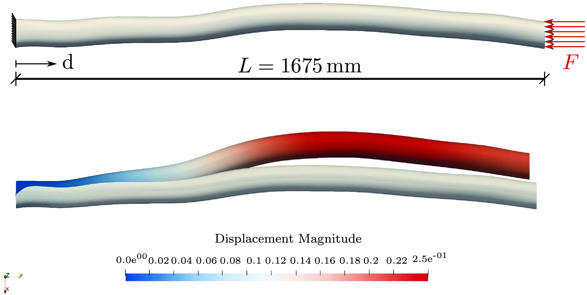
Figure 13. Longitudinally loaded compression test of the unprocessed slender wooden branch. The deformation figure is given in the bottom view.
The stress plots from Figure 14 in the x and z directions show that the perpendicular stresses cannot be neglected since they vary with the factor
![]() ${10^1}$
–
${10^1}$
–
![]() ${10^2}$
. This should underline how important an accurate representation of the actual geometry is. Even minor imperfections of an approximately straight wooden branch result in significant deflection radial to the center line.
${10^2}$
. This should underline how important an accurate representation of the actual geometry is. Even minor imperfections of an approximately straight wooden branch result in significant deflection radial to the center line.
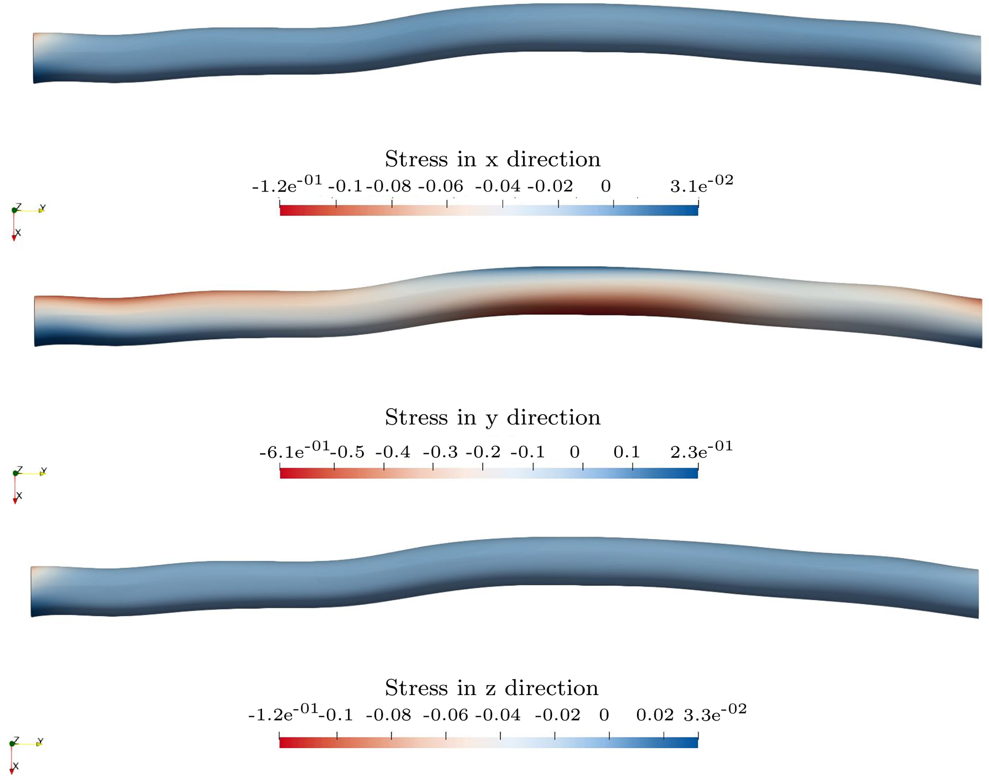
Figure 14. Stress distributions in x, y and z directions for stresses separated.
Throughout the polar description of the parametric model, different densities, stiffness and shear stiffness of naturally grown wood can be described in the future based on the cross-sectional radius. Using multiple Young’s moduli over the cross-sectional area results in more accurate simulations. A preliminary simulation is conducted in 15 with a distribution of Young’s modulus smaller in the center. This is a consideration taken as a reference from the density variation of a softwood or deciduous tree (Matsuo-Ueda et al. Reference Matsuo-Ueda, Tsunezumi, Jiang, Yoshida, Yamashita, Matsuda, Matsumura, Ikami and Yamamoto2022), which is less resistant at the core. The simulation results show less deformation compared to a reference simulation of a uniform averaged E-modulus
![]() ${E_m}$
(Figure 15).
${E_m}$
(Figure 15).

Figure 15. Comparison of a branch under bending for calculation with a constant mean modulus of elasticity distribution, with calculation with different E-modulus ranges.
Bifurcated elements
Multiple patches and center lines in the longitudinal direction are necessary when modeling bifurcated structural elements. Figure 16 shows the structural analysis of a wooden bifurcation model. The structure is loaded in the xy-plane toward the axes and clamped at the support. An isotropic linear elastic material model was used for the simulation. The advantages of the polar geometric description will be used for material modeling in future works.
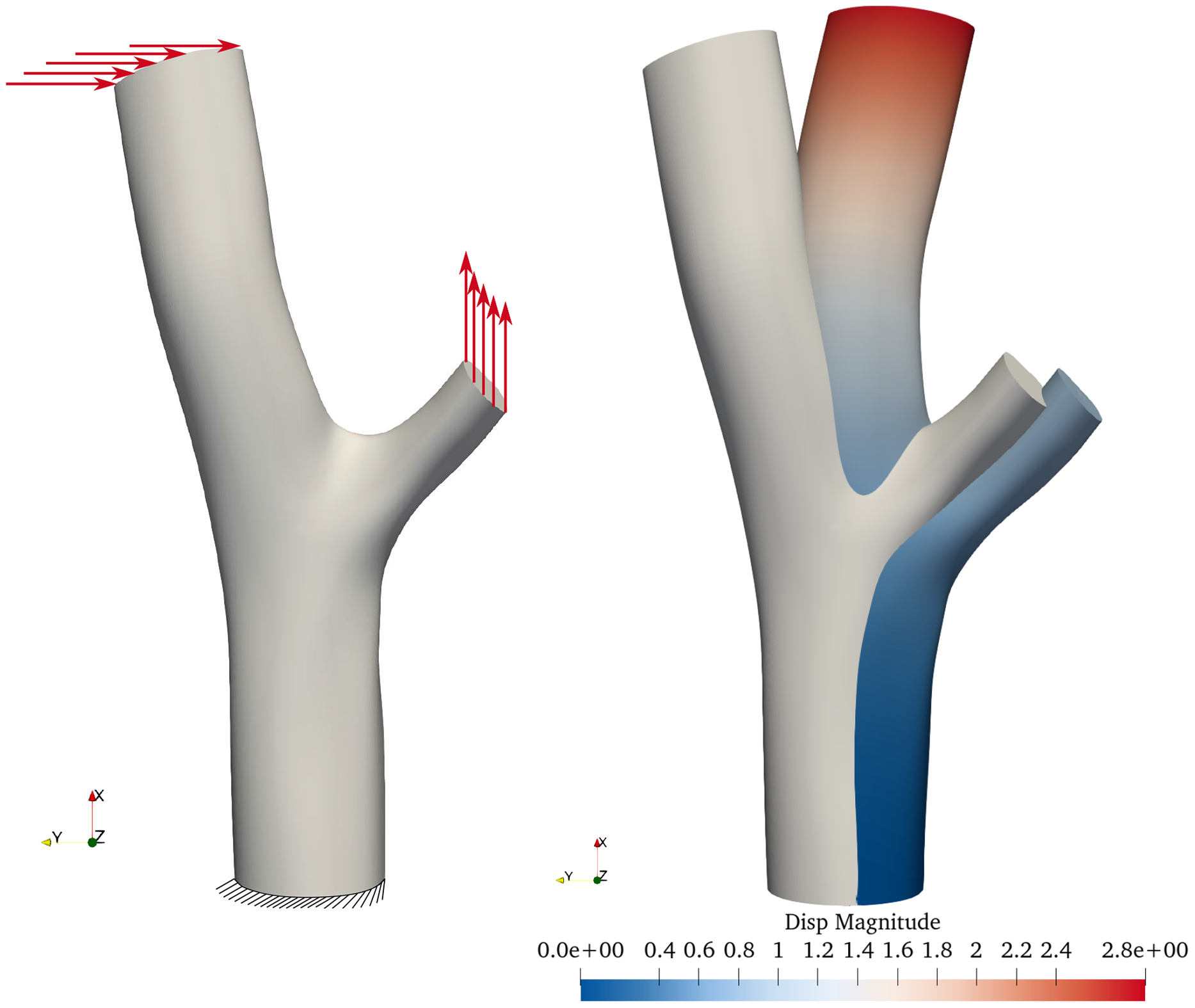
Figure 16. Combined bending and tension test, while bending is induced by force in the y direction, the tensional force applies in the x direction. A structural model with boundary and loading is given on the left. The deformation figure of loaded and clamped bifurcation in the bending test is on the right. The displacement field is plotted over the deformed structure.
Construction elements
The analysis of naturally grown elements enables the estimation of load capacities based on their geometry, allowing for their use both individually and collectively in load-bearing structures that mimic living tree architectures. This study focuses on individual elements such as straight, curved and bifurcated forms, exploring diverse construction methods tailored to various structural typologies. Bifurcated elements are particularly emphasized for their mechanical capabilities, as depicted in Figure 17, where structural connections are optimally positioned at the ends of the center line. In this project, structural positioning aligns with growth curves rather than mere geometric approximations to ensure that wood loads follow the direction of the grain, thereby enhancing structural integrity. Moreover, given the noted deviations and resulting static eccentricities between geometric and growth curves in existing literature, future numerical investigations will assess these deviations to determine the potential for design adaptations or fidelity adjustments in the constructions.
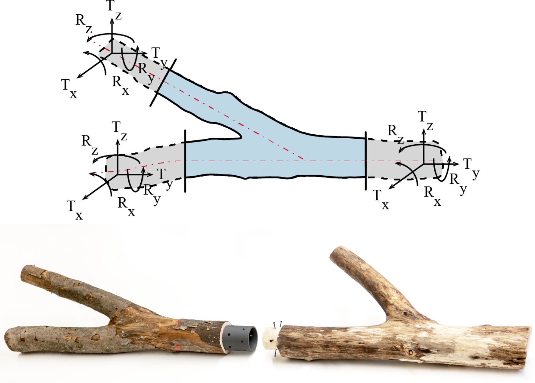
Figure 17. Above: Mechanical capacity of raw wood elements. Below: Development of joints that allow the transmission of loads, displaced from the topological node – off-knot connection.
The analysis of naturally grown elements enables the estimation of load capacities based on their geometry, allowing for their use both individually and collectively in load-bearing structures that mimic living tree architectures. This study focuses on individual elements such as straight, curved and bifurcated forms, exploring diverse construction methods tailored to various structural typologies. Bifurcated elements are particularly emphasized for their mechanical capabilities, as depicted in Figure 17, where structural connections are optimally positioned at the ends of the center line. In this project, structural positioning aligns with growth curves rather than mere geometric approximations to ensure that wood loads follow the direction of the grain, thereby enhancing structural integrity. Moreover, the precise 3D modeling that converts mesh to a NURBS model directly informs the design of the final bridge structure by meticulously mapping each element’s geometry and growth directions, ensuring strategic placement of joints and supports for optimal structural integrity and load-bearing efficiency. This modeling is key for addressing noted deviations and potential static eccentricities between geometric and growth curves, with future numerical investigations planned to further refine design adaptations or fidelity adjustments in the constructions.
Conventional timber bar structures, typically configured as trusses, demand intricate connection nodes, often made using slotted steel plates. These critical connections are strategically positioned at structural nodes. Using the capabilities of naturally grown timber – especially the bifurcations – Trautz et al., Reference Trautz, Moreno, Spahn and Klinkel2024) introduces an innovative approach by developing “off-knot” structural nodes that function as rigid nodes.
Bar-type structures. Key study: Growing bridge
The methodologies employed in Moreno Gata, Seiter, et al. (Reference Moreno Gata, Seiter, Grizmann and Trautz2023) illustrate various truss configurations featuring rigid nodes. The bending moments at the corners within these frameworks exhibit characteristics typical of Vierendeel and frame systems. In these trusses, the elements needed to connect nodes can be supplemented with either straight or curved bars. The positioning of these elements is determined by the scheme illustrated in Figure 18.
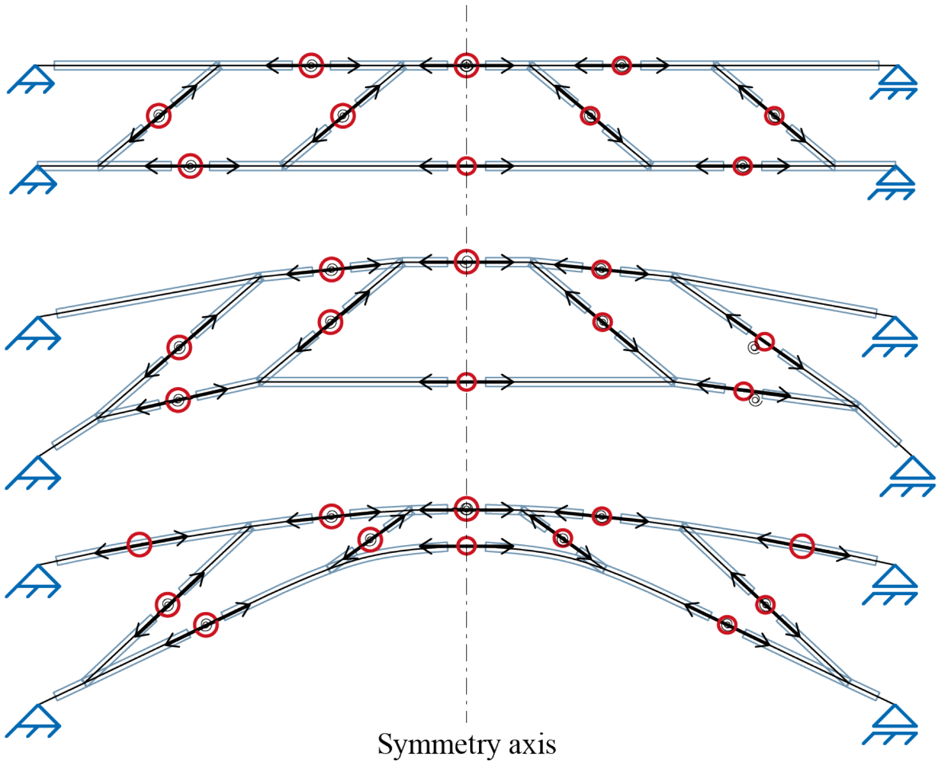
Figure 18. Diagram of a framework with rigid nodes, where the joint positions are adapted to suitable locations based on the material stock. This framework is later applied with bifurcations and curved elements in three dimensions.
As a demonstration of the analyzed concepts, the design and construction of a load-bearing structure composed of two mirrored frameworks have been proposed. This structure’s topology is applicable in different scenarios, such as a roof truss. However, its application was chosen for constructing a self-supporting bridge, serving as a connection between various disciplines that have been part of this project (see Figure 1). Methods of optimization, based on the reuse of elements and circular design principles (Amtsberg, Huang, Marshall, et al. Reference Amtsberg, Huang, Marshall, Moreno Gata and Mueller2021) (Huang et al. Reference Huang, Alkhayat, De Wolf and Mueller2021), aided in the design of this construction by implementing a dataset – collected elements from the local forest in Aachen – shown in Figure 3.
The scanned elements, totaling 43, were individually analyzed. The outcome of static considerations, cross-section assessments, material properties of each species and the optimal positioning of connection points resulted in a structure composed of 26 elements. Five hardwood species were utilized: oak, beech, hornbeam, birch and maple (see Figure 20).
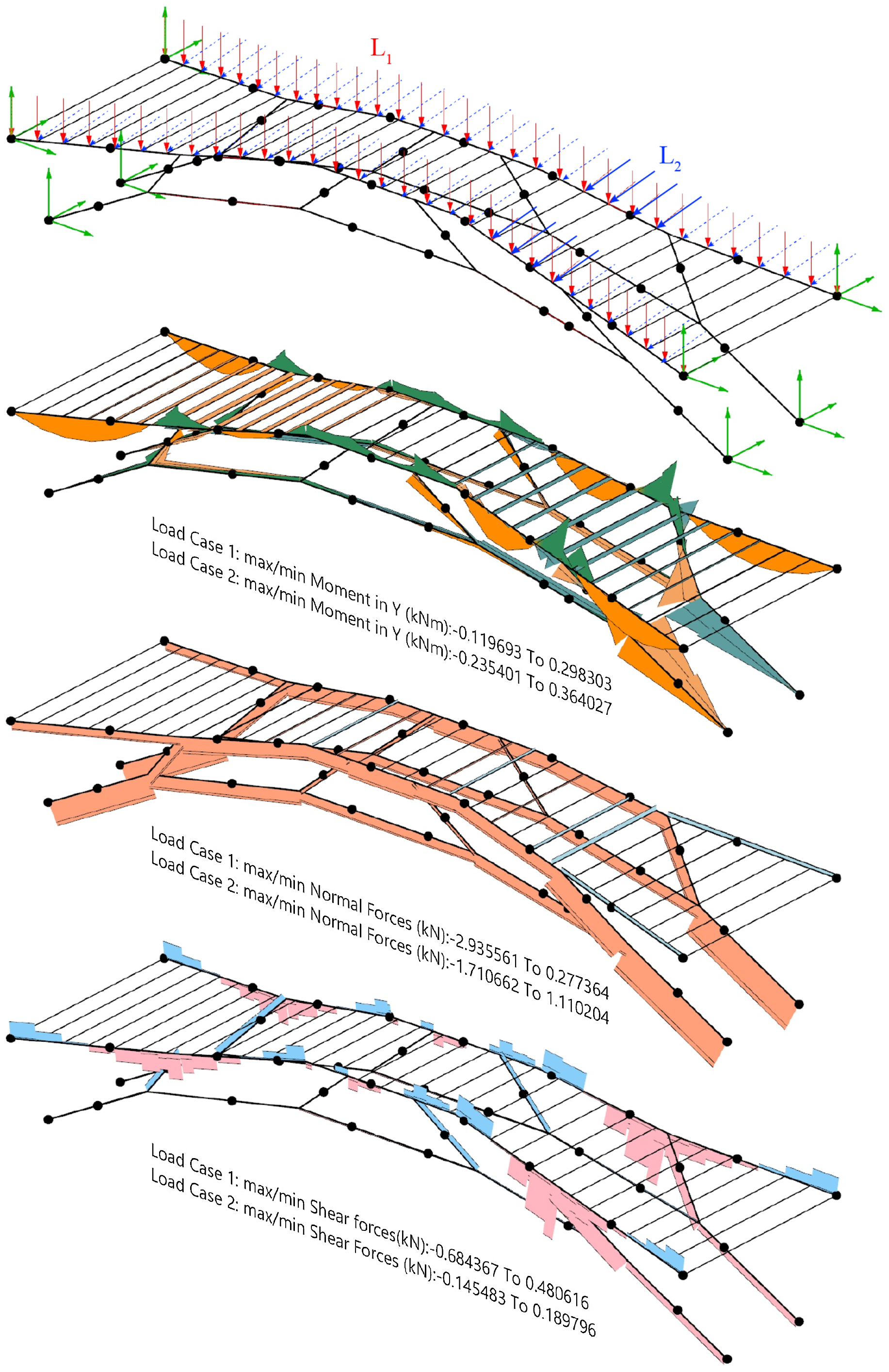
Figure 19. Static analysis: Load cases
![]() ${L_1}$
and
${L_1}$
and
![]() ${L_2}$
and joints. Graph of moments, normal forces and shear forces.
${L_2}$
and joints. Graph of moments, normal forces and shear forces.
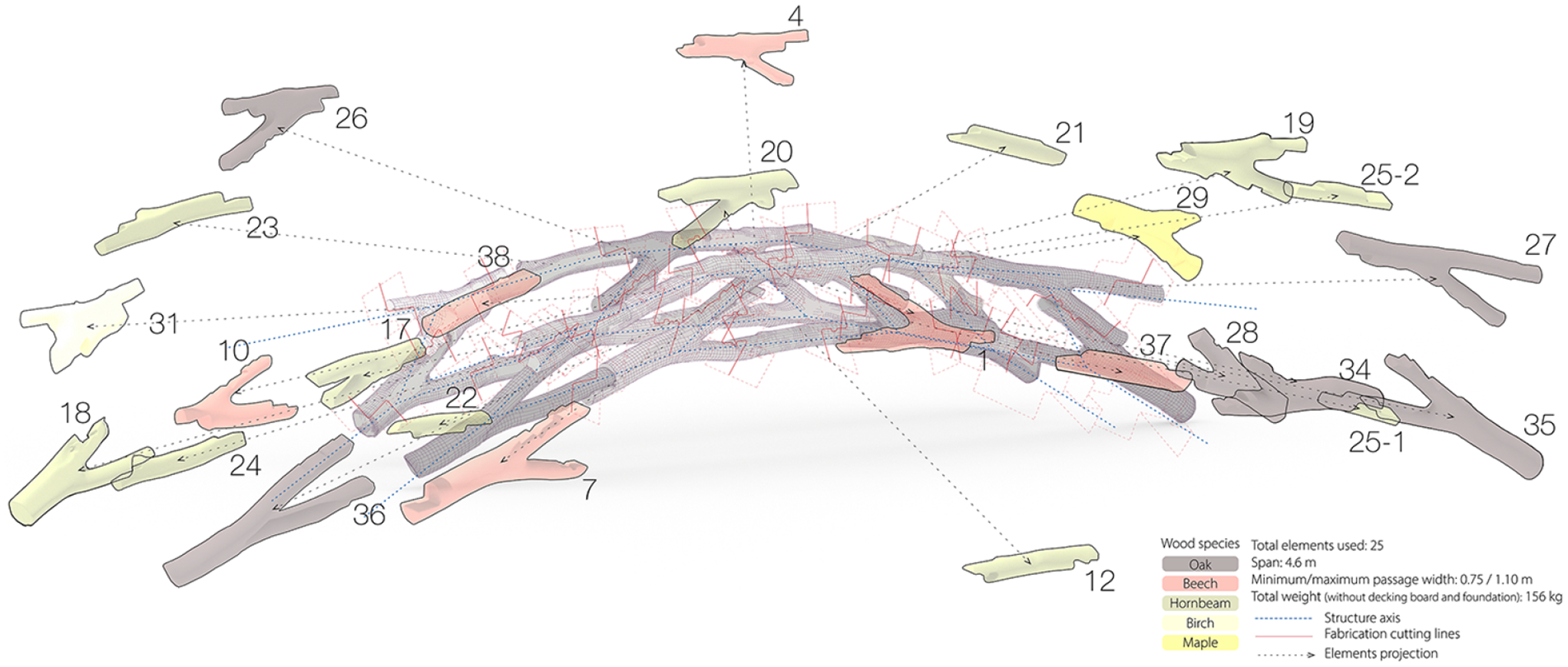
Figure 20. Structure composition. Numbered elements with color-coded species identification and construction joints.
The assembled structure spans 4.6 m with a total length of 6.7 m, as illustrated in Figure 20. The structure narrows at its central point, providing a usable clearance of 0.75 m, opening outward and varying in height. The conceptualized bridge is named “Growing Bridge” because this topology can be additively expanded toward the ends. In other words, additional elements can be added, increasing the span, if necessary to cover a larger space. Elements to be added must fulfill criteria such as an increased cross-section (Figures 19 and 21).
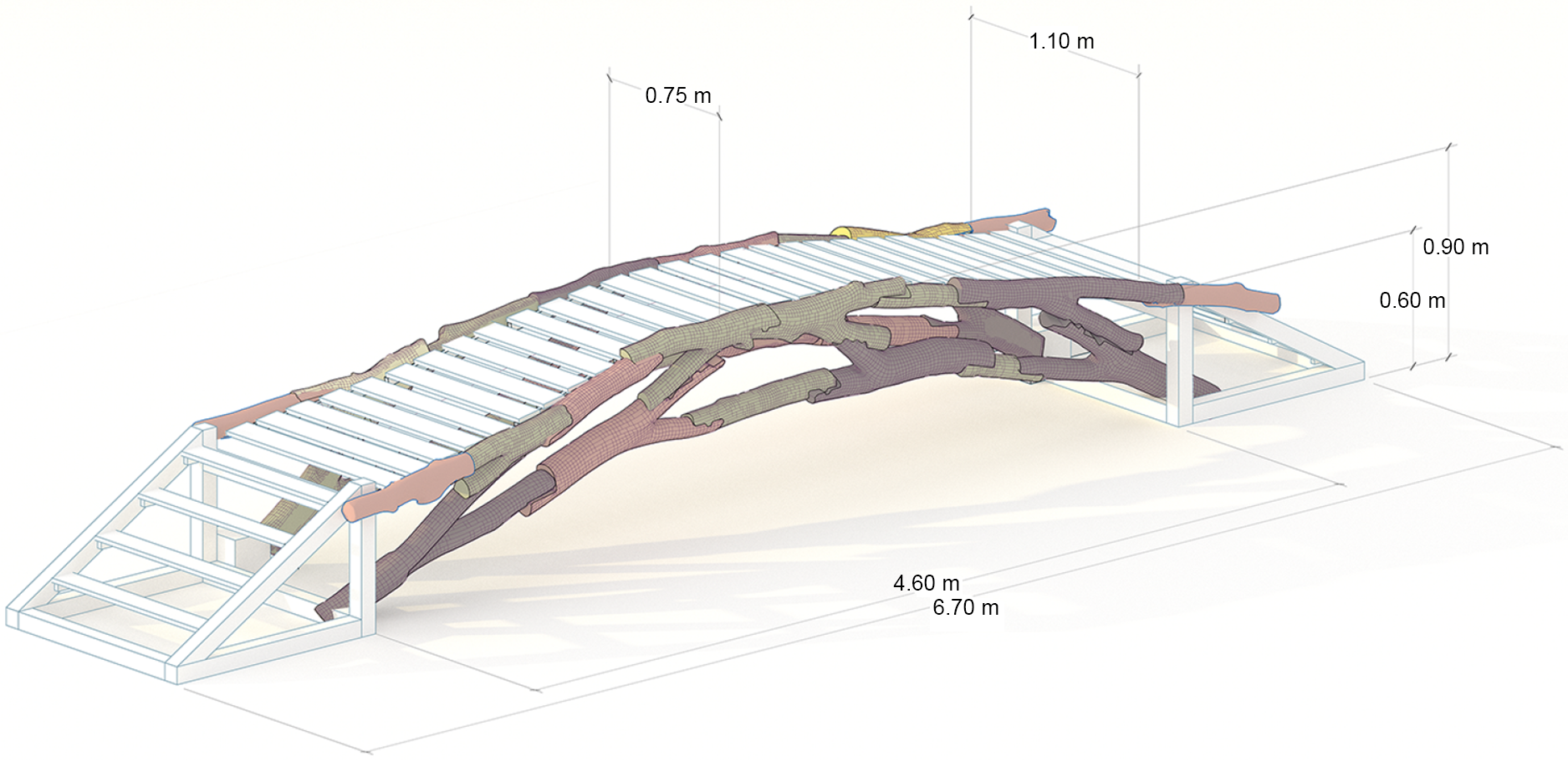
Figure 21. Assembled structure.
Development of structural joints
The development of structural joints in the off-knot construction primarily begins with a three-dimensional definition of the stock material, utilizing a 3D mesh converted to a NURBS model to accurately determine geometrical and growth directions necessary for correct joint positioning. This method prevents the introduction of incorrect static eccentricities that could compromise the structure’s integrity. The joints themselves are designed based on a combination of shape and interlocking, supplemented by the use of fully threaded screws. This approach allows for assembly and disassembly without the need for adhesive materials, facilitating easier maintenance and potential reconfiguration of the construction elements.
For the joint development, an automated system for positioning cut planes at each joint was implemented (see Figure 22). These joint planes were parametrically developed and aligned along the center line, facilitating the transmission of loads through the natural wood geometry. Despite static calculations treating the joints as rotational springs, receiving only axial forces, screws were strategically placed to ensure proper load transmission and prevent asymmetric horizontal forces from causing dislocations at the joints.

Figure 22. Structural connection: Photo of a construction element from an oak specimen, depicting the position of the contact faces of the joint, considering the central line of the tree’s growth.
The structure was fabricated and assembled during the Summer Semester of 2023 as part of a research assignment course in the Master of Architecture program at RWTH Aachen University (Chair of Structures and Structural Design) (Figure 23).
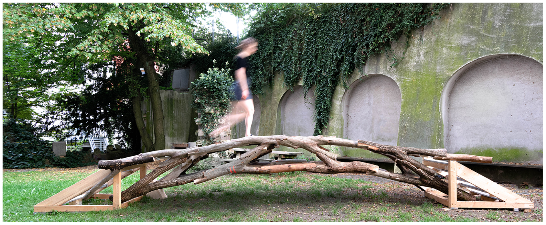
Figure 23. Final state. The construction is currently located in the inner courtyard of the Faculty of Architecture (Schinkelstr. 1, 52064, Aachen, Germany) for testing and public use.
Sandwich panels
The bar-type structures are therefore the most used method in literature, and an example is presented here. However, alternative concepts can be explored, such as sandwich structures, where raw wood is positioned in the core of a wood panel. The project “reGrowth,” as outlined in Moreno Gata et al. (Reference Moreno Gata, Amtsberg, Stephens, Menges and Trautz2024), illustrates a practical application of these principles. By aligning the growth direction of timber elements with stress trajectories, it achieves a naturally grown timber panel that is oriented in harmony with the distribution of forces, ensuring optimal stress alignment.
Future works
Automatizing process
Work in progress to extend the findings presented here. In particular, geometry and simulation developments are currently being automated to provide an open-source package.
Besides that, the automated interpretation of timber can be enhanced through the application of neural networks, proving their applicability in growth ring recognition (Abdeljaber, Habite and Olsson Reference Abdeljaber, Habite and Olsson2023). This research encompasses a testing phase that leverages the neural network (Detectron2 2023) to identify crucial points or zones within wood trunks indicative of tree growth from CT scans (see Figure 24). It utilizes Cartesian information, derived from the perimeter and the pith – the central point, to ascertain the growth path of the tree – center line. This data proves instrumental in training the neural network and is subsequently implemented in new CT scans. The primary objective lies in the recognition of shifts in the tree’s center of gravity due to static loads.
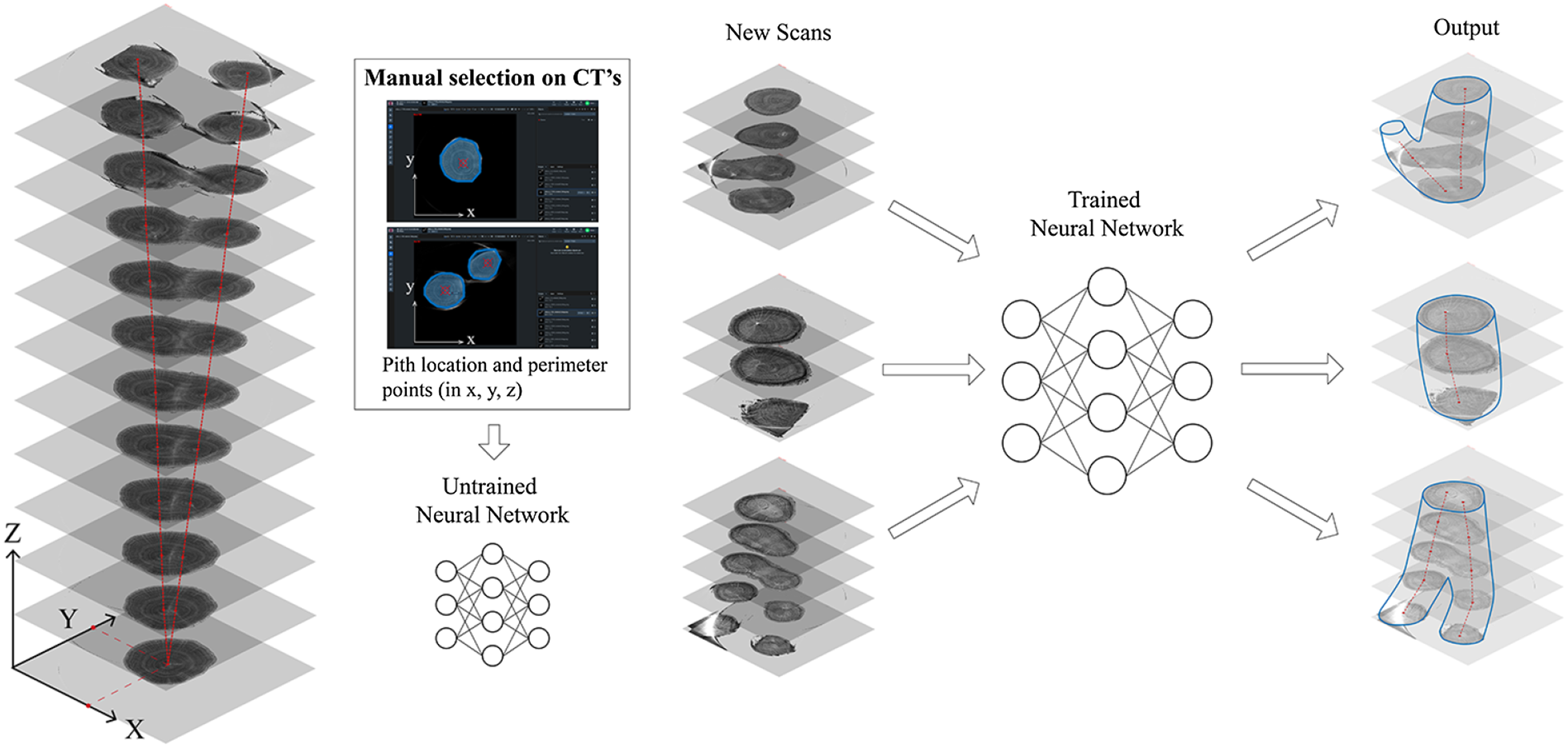
Figure 24. Automation of geometric development based on CTs through neural networks.
Experiments in plant growth
This research also extends into the study of growing trees and plant guidance. For the past three years, an ongoing data collection on plant growth has been conducted as part of a current research project Moreno Gata, Grizmann and Trautz (Reference Moreno Gata, Grizmann and Trautz2021). Regular documentation of several Paulownia specimens is been compiled, including measurements of the base perimeter and diameter, to analyze trunk curvature. The collected data seeks to demonstrate that the static response of the young tree contributes to an elliptical shaping of its trunk (see Figure 25).
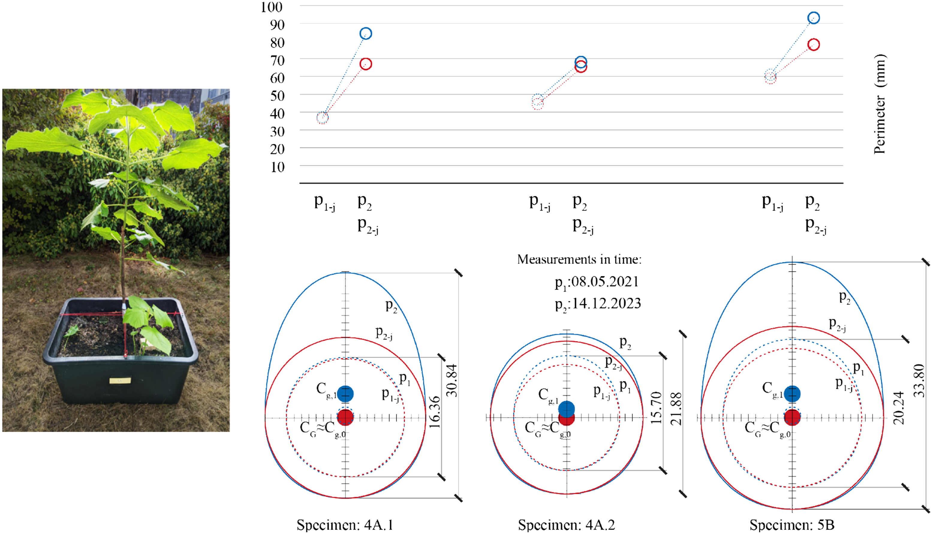
Figure 25. Continuous growth measurements on 3-year-old Paulownia trees. Deviated perimeter
![]() ${p_2}$
, from
${p_2}$
, from
![]() ${p_1}$
tending to an egg-like shape and displacement of the center of mass. In red, the tangent circle reference
${p_1}$
tending to an egg-like shape and displacement of the center of mass. In red, the tangent circle reference
![]() ${p_{1 - j}}$
and
${p_{1 - j}}$
and
![]() ${p_{2 - j}}$
.
${p_{2 - j}}$
.
Conclusions
The handling of trees and their raw wood in construction technology expands the possibilities for timber utilization, including previously overlooked wood such as undergrowth logs and various curved logs. Homogenized, highly processed timber is not imperative for all structural applications. Naturally grown timber can be integrated with traditionally processed semi-finished wood products like boards, beams or panels and can also be incorporated into conventional timber construction methods.
With naturally grown timber components, wood species that were previously unused due to difficulties in processing, such as curved, bifurcated or twisted growth, can now find application. These considerations add value to a natural material that is underutilized. Moreover, alongside the strength values of the cross-sections of naturally polar-structured wood, mechanical verification becomes feasible, expanding its potential applications, including in load-bearing structures.
Ongoing research and geometric developments create conditions for a significantly broader use of wood in construction and load-bearing structures than before. A noninvasive documentation procedure, 3D scanning and the automation of geometrical and analytical procedures significantly simplify the application process, enabling the calculation of raw wood and trees in their real form. This advancement facilitates a more aligned utilization of timber with its natural properties, allowing it to seamlessly return to the natural materials cycle without restrictions at the end of its use.
Data availability statement
Datasets are currently available upon request. Future works will include the establishment of a dedicated repository to facilitate automated processes and plugins. Interested parties can contact the corresponding author for further details.
Acknowledgments
This paper and the research behind it would not have been possible without the support of our colleagues at ibg-2, Juelich Research Center: Prof. Dr. Ulrich Schurr, Dr. Robert Koller, Dr. Daniel Pflugfelder, Dr. Carel Windt and Dr. Silvia Schrey and the team Landesbetrieb Wald und Holz NRW Regional Forestry Office Rureifel – Juelicher Boerde, especially thanks to Andreas Wintraken.
The authors would like to extend special thanks to Trako’s student assistants: Sheldon Stephens, Tobias Grueters, Viktor Wages and Raman Suliman; and LBB’s student assistant: Beke Pierick.
Author contribution
The authors contributed to this work in the following ways: KM: conceptualization, methodology, writing – original draft. FS: data analysis, simulation, visualization. SK: Supervision, project administration, funding acquisition. MT: supervision, project administration, funding acquisition.
Financial support
The financial support of the Deutsche Forschungsgemeinschaft (DFG, German Research Foundation) under grant no. TR 800/20-1 and grant no. KL 1345/18-1 (project no. 512769030) is gratefully acknowledged.
Competing interests
The authors declare no conflict of interest. The founders had no role in the design of the study; in the collection, analyses or interpretation of data; in the writing of the manuscript; or in the decision to publish the results.
Ethics statement
This research project does not involve human subjects, animal experimentation or any other activities requiring ethical approval. As such, an ethics statement is not applicable to this study.


Comments
No accompanying comment.