


1. Introduction
Cross-stream or lateral migration of particles in a pressure-driven flow has been an active area of research due to its relevance in many industrial (Shannon et al. Reference Shannon, Bohn, Elimelech, Georgiadis, Marinas and Mayes2008; Vidic et al. Reference Vidic, Brantley, Vandenbossche, Yoxtheimer and Abad2013) and biological (Nagrath et al. Reference Nagrath2007) applications. The phenomenon of lateral migration is specifically used for the manipulation of biological cells and particles in various microfluidic applications (Xuan, Zhu & Church Reference Xuan, Zhu and Church2010; Amini, Lee & Di Carlo Reference Amini, Lee and Di Carlo2014). The wall-normal component of force acting on the particle is responsible for its lateral migration and it is usually called the lift force. The lift force which is often relatively small in magnitude plays a central role in determining the final position of an individual particle and the particle distribution in particulate flows (Hidman et al. Reference Hidman, Ström, Sasic and Sardina2022).
The lateral motion of a particle was first investigated experimentally by Segre & Silberberg (Reference Segre and Silberberg1961) in a tube flow. Their observation was later confirmed by many experimental (Karnis & Mason Reference Karnis and Mason1966; Matas, Morris & Guazzelli Reference Matas, Morris and Guazzelli2004b) and numerical (Feng, Hu & Joseph Reference Feng, Hu and Joseph1994; Yang et al. Reference Yang, Wang, Joseph, Hu, Pan and Glowinski2005) studies. The same observation was made in rectangular channels where particles move towards or away from the channel wall in the cross-streamwise direction (Frank et al. Reference Frank, Anderson, Weeks and Morris2003; Del Giudice et al. Reference Del Giudice, Romeo, D'Avino, Greco, Netti and Maffettone2013; Wang, Yu & Lin Reference Wang, Yu and Lin2018; Yuan et al. Reference Yuan, Zhao, Yan, Tang, Alici, Zhang and Li2018). The situation becomes more involved when the ambient fluid is viscoelastic as the fluid elasticity plays its role in pushing the particle towards the centre of the channel (Seo, Kang & Lee Reference Seo, Kang and Lee2014). In the case of viscoelastic fluids, most of the existing literature is primarily focused on solid particles suspended in a viscoelastic fluid (Villone et al. Reference Villone, D'Avino, Hulsen, Greco and Maffettone2013). In the absence of inertia, the cross-stream migration of a non-deformable particle is not possible to occur in a confined Newtonian fluid flow due to the inherent reversibility of Stokes flow. However, the nonlinear characteristics of viscoelasticity provide the required irreversibility making the lateral migration possible in a complex fluid even with negligible inertia. The lateral migration of particles in complex fluids and their application in manipulating the particles in various microfluidic devices have been summarized in the review paper by D'Avino, Greco & Maffettone (Reference D'Avino, Greco and Maffettone2017).
In the presence of both inertia and viscoelasticity, several factors determine the orientation of particle migration in a pressure-driven channel flow. Some of these factors reported in numerous studies so far include shear-induced lift force (Saffman Reference Saffman1965), wall-induced lift force (Shi et al. Reference Shi, Rzehak, Lucas and Magnaudet2020), fluid elasticity (Karnis & Mason Reference Karnis and Mason1966; Raffiee, Dabiri & Ardekani Reference Raffiee, Dabiri and Ardekani2017), initial position of the particle (e.g. Villone et al. Reference Villone, D'Avino, Hulsen, Greco and Maffettone2011), geometry of the channel (Yu et al. Reference Yu, Wang, Lin and Hu2019), the shear thinning of the ambient fluid (Li, McKinley & Ardekani Reference Li, McKinley and Ardekani2015) and particle rotation rate (the Magnus effect). The effects of one or more of these factors determine the migration of a particle towards or away from the channel wall. Moreover, the deformability of an object adds further complexity to this phenomenon, and therefore, the complex dynamics of lateral migration of deformable particles in viscoelastic fluids is yet to be fully explored. As a result of this migration, some interesting secondary flow features also emerge in the vicinity of the particle. One of them is a secondary flow which is perpendicular to the primary flow (streamwise) direction and may have a velocity as large as the order of the particle migration velocity. However, this secondary flow is generated in non-circular channels only by the viscoelastic fluids having a non-zero second normal stress difference (Debbaut et al. Reference Debbaut, Avalosse, Dooley and Hughes1997).
When a spherical particle moves with a relative velocity in a shear flow, a force is exerted on the particle by the surrounding fluid in a direction perpendicular to its relative motion. This force is known as the shear-induced lift force, first calculated analytically by Saffman (Reference Saffman1965) for a solid sphere. This force pushes the particle towards the channel wall until it is balanced by the wall-induced lift force (Feng et al. Reference Feng, Hu and Joseph1994; Matas, Morris & Guazzelli Reference Matas, Morris and Guazzelli2004a). The flow field around the particle is significantly influenced by the presence of the wall. The wall decelerates the motion of the particle in the streamwise direction due to extra drag and repels it away from the wall if the characteristic length of the particle is much smaller than the channel size. If the characteristic length of the particle is comparable to the channel size, like the motion of bubbles in capillaries, the channel walls constrain the motion of the immersed object, as explained by Michaelides (Reference Michaelides2006).
The well-known Magnus effect (rotation-induced lift force) is another factor influencing the migration of an object in the channel flow. For a solid particle having the no-slip condition on its surface, the difference in the relative fluid velocity on its sides may cause it to rotate. This shear-induced rotation generates an additional transverse pressure difference and the resulting lift force is referred to as the ‘Magnus effect’ (Rubinow & Keller Reference Rubinow and Keller1961). Instead of a solid particle, if the object is deformable, the deformability induces yet another lateral migration directed towards the channel centre (Chan & Leal Reference Chan and Leal1979). Similarly, the initial position of the particle in the channel has a direct impact on its lateral migration as dictated by the gradient of velocity at that initial location. The size of the particle as compared with the channel is another important variable to be considered while analysing the lateral migration in a pressure-driven flow. It is generally characterized by the blockage ratio (Di Carlo Reference Di Carlo2009) defined as  $b=d/H$, where
  $d$ is the particle size (e.g. diameter) and
  $H$ is the channel width. It has been observed in both experimental (Lim et al. Reference Lim, Ober, Edd, Desai, Neal, Bong, Doyle, McKinley and Toner2014) and numerical (Mortazavi & Tryggvason Reference Mortazavi and Tryggvason2000) works that a deformable object with a diameter beyond a certain limit migrates towards the channel centre due to deformation-induced lift force while a smaller one migrates towards the wall due to inertial lift force. This feature is used in many microfluidic devices for sorting particles of different sizes (Nam et al. Reference Nam, Namgung, Lim, Bae, Leo, Cho and Kim2015).
The Magnus effect, shear-induced lift force and wall-induced lift force may be referred to as the ‘inertial effects’ as all these forces primarily originate due to fluid inertia. If the ambient fluid is viscoelastic, the elastic effects tend to push the object towards the centre (Seo et al. Reference Seo, Kang and Lee2014) while the inertial effects tend to move it towards the channel wall. The relative strength of inertia and elasticity determines the final equilibrium position of a non-deformable particle in a channel. This interplay between inertia and elasticity is quantified by the elasticity number, defined as  $El= Wi/Re$, where
  $Wi$ and
  $Re$ are the Weissenberg number and the Reynolds number, respectively. Furthermore, if the ambient fluid exhibits a shear-thinning behaviour as well, it has been reported by Li et al. (Reference Li, McKinley and Ardekani2015) that the shear thinning amplifies inertial effects and thus promotes particle migration towards the wall. Hazra, Mitra & Sen (Reference Hazra, Mitra and Sen2020) experimentally studied the role of shear thinning on the cross-stream migration of droplets in a confined shear flow for
  $Re<1$. They observed that larger droplets followed their original streamlines while the smaller ones migrated towards the centre. Similarly, to predict the role of elasticity, Mukherjee & Sarkar (Reference Mukherjee and Sarkar2014) performed computational simulations of a viscoelastic drop in a Newtonian fluid for a linear shear flow with negligible inertia. They found a non-monotonic impact of elasticity on the migration velocity of the droplet.
The above-mentioned list of factors affecting the migration dynamics of a deformable object is still not exhaustive. In the presence of surfactant contamination, the surfactant-induced Marangoni stresses oppose the inertial lift force and can completely alter the migration dynamics of an object. In our earlier work (Muradoglu & Tryggvason Reference Muradoglu and Tryggvason2014; Ahmed et al. Reference Ahmed, Izbassarov, Lu, Tryggvason, Muradoglu and Tammisola2020b), it was observed that, in the pressure-driven channel flow of a Newtonian fluid, clean spherical bubbles move towards the wall while the deformable ones migrate away from it. However, even the spherical bubbles can move away from the wall in the presence of a strong enough surfactant.
Although there are a large number of experimental and numerical works devoted to solid particle migration, much less attention has been paid to the combined effects of inertia, viscoelasticity, and shear thinning on the lateral migration of a deformable fluid particle and only a few details are available in the existing literature, which motivates the present study. The main focus here is to explore the combined effects of fluid inertia, viscoelasticity and particle deformability on its lateral migration in a shear-thinning viscoelastic fluid. For this purpose, fully interface-resolved numerical simulations are performed using an Eulerian–Lagrangian method (Tryggvason et al. Reference Tryggvason, Bunner, Esmaeeli, Juric, Al-Rawahi, Tauber, Han, Nas and Jan2001) for a wide range of relevant flow parameters to explore the features of this complex flow field. In addition to the lateral migration, the particle-induced elastic instability and its impact on the onset of a path instability, the effect of shear thinning, and the resulting flow are investigated computationally. The secondary flow field developed due to the second normal stress difference in the flow is also examined and quantified.
The rest of the paper is organized as follows. The problem statement and the computational set-up are described in the next section. The governing equations and the numerical method are briefly described in § 3. The results are presented and discussed in § 4 followed by the conclusions in § 5. A grid convergence study is conducted and the results are presented in the Appendix.
2. Problem statement and computational set-up
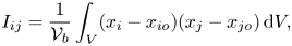
Microfluidic devices usually use channels with rectangular cross-sections due to their relative ease of fabrication. If the aspect ratio of the channel is reduced, the relative influence of channel walls on the flow field becomes more pronounced (Villone et al. Reference Villone, D'Avino, Hulsen, Greco and Maffettone2013). The limiting case is obtained for a square-shaped cross-section, which is selected in the present study. Figure 1(a) shows the computational domain which is a square channel with the dimensions of  $H$,
$H$,  $L$ and
  $H$ in the
  $x$,
$x$,  $y$ and
  $z$ directions, respectively. Periodic boundary conditions are applied in the streamwise (
 $y$) direction whereas the other two directions (
 $x$ and
  $z$) have no-slip/no-penetration boundary conditions. The centroid of the particle is denoted by
  $(x_b,y_b,z_b)$ and a spherical fluid particle of diameter
  $d$ is initially located at
  $(x_{bi},y_{bi},z_{bi}) = (0.5H, H, 0.25H)$ unless specified otherwise. The value of
  $H$ is set to
  $4d$. After performing the simulations by gradually increasing the length of the channel in the streamwise (
 $y$) direction to check the effects of periodicity, the channel length is set to
  $L=4H$, which is found to be sufficient to eliminate any significant effects of periodicity.

Figure 1. (a) Computational domain shown with the schematic representation of a deformable fluid particle migrating towards the wall of the channel. The streamlines of the flow are shown above the particle in the  $xz$-plane once the particle reaches its equilibrium position closer to the wall. The distribution of the second normal stress difference (
 $N_2$) is shown in the
  $xz$-plane upstream of the particle at
  $y=3.95$. (b) Eight vortices showing the secondary flow field in the same
  $xz$-plane away from the particle at
  $y=3.95$ are shown. The velocity vectors are coloured by the magnitude of flow velocity in that plane. (
 $Re=18.9, El=0.05, Eo=0, Ca=0.01, \alpha =0.1$.)
The deformable particle is at rest initially at  $t=0$ and a constant pressure gradient
  ${\rm d}p_0/{{\rm d} y} = -U_{o}\mu _{o}{\rm \pi} ^3 / 4kH^2$ is applied in the
  $y$-direction to drive the flow, where
  $U_{o}$ is the flow velocity at the centreline of the channel in the case of a fully developed single-phase laminar flow and
  $k$ is a geometric constant. For a square channel,
  $k\approx 0.571$ (Fetecau & Fetecau Reference Fetecau and Fetecau2005). It is important to note that
  $U_o$ is the centreline velocity in the channel for the Newtonian and Oldroyd-B fluids. In a Giesekus fluid, the centreline velocity becomes greater than
  $U_o$ due to the shear-thinning effect. However, throughout this paper, all the non-dimensional numbers are defined based on
  $U_o$ corresponding to the applied pressure gradient in the Newtonian fluid unless stated otherwise. Here,
  $H$,
$H$,  $U_{o}$ and
  $H/U_{o}$ are used as the length, velocity and time scales, respectively. The stresses are normalized by
  $\mu _{o}U_{o}/H$. The normalized non-dimensional quantities are denoted by the superscript (
 $^*$). The blockage ratio (
 $b=d/H$) is fixed at
  $0.25$. The density (
 $\rho _{o}/\rho _{i}$) and the viscosity (
 $\mu _{o}/\mu _{i}$) ratios are set to
  $10$ in this study where the subscripts
  $i$ and
  $o$ denote the dispersed and continuous phases, respectively. These comparatively smaller ratios are used to reduce the spatial error exacerbated by sudden jumps in material properties across the interface and enhance numerical stability, and thus relax the excessive grid resolution requirement and time step restrictions. Tasoglu et al. (Reference Tasoglu, Kaynak, Szeri, Demirci and Muradoglu2010) and Olgac, Izbassarov & Muradoglu (Reference Olgac, Izbassarov and Muradoglu2013) have demonstrated that the results are not affected significantly for these types of flows at higher ratios. In the present case of pressure-driven viscoelastic channel flow, although not shown here, simulations have been performed for the density and viscosity ratios of
  $20$,
$20$,  $40$ and
  $80$ as well, and the results are found to be not very sensitive to the increase in the density ratio, i.e. the difference is less than 1 % but more sensitive to the viscosity ratio due to a higher contribution of polymeric viscosity in a concentrated polymer solution. It is observed that at a higher viscosity ratio, the secondary flow velocity induced by the fluid particle once it attains its equilibrium position (as will be discussed in detail in § 4.4) is not much affected but the lateral displacement of the fluid particle is still significantly influenced by this higher viscosity ratio. As the viscosity ratio in the liquid–air system of a complex fluid flow can be as high as
  $10^8$ depending upon the molecular weight and concentration of the polymer molecules, the term ‘deformable fluid particle’ is used instead of a bubble in the present study.
In addition to the density and viscosity ratios, the flow conditions are characterized by the following non-dimensional numbers defined as
 \begin{align} Re = \frac{\rho_o U_o H}{\mu_o},\quad Wi = \frac{\lambda U_o}{H},\quad Eo = \frac{g\Delta\rho d^2}{\sigma},\quad Mo = \frac{g\mu_o^4}{\rho_o\sigma^3},\quad Ca = \frac{\mu_o U_o}{\sigma},\quad \beta = \frac{\mu_s}{\mu_o}, \end{align}
where  $Re$,
$Re$,  $Wi$,
$Wi$,  $Eo$,
$Eo$,  $Mo$ and
  $Ca$ denote the Reynolds, Weissenberg, Eötvös, Morton and capillary numbers, respectively. Note that the Morton number is not an independent parameter. Additionally,
  $\beta$ is the ratio of solvent viscosity to zero shear viscosity of the viscoelastic fluid. The density difference is defined as
  $\Delta \rho = \rho _o-\rho _i$. The particle deformation (
 $\chi$) is quantified as
 \begin{equation} \chi = \sqrt{I_{max}/I_{min}}, \end{equation}
where  $I_{max}$ and
  $I_{min}$ are the maximum and minimum eigenvalues of the second moment of inertia tensor defined as
 \begin{equation} I_{ij} = \frac{1}{\mathcal{V}_b}\int_{V}(x_{i} - x_{io})(x_{j} - x_{jo})\,{\rm d}V, \end{equation}
where  $\mathcal {V}_b$ is the volume of the particle, and
  $x_{io}$ and
  $x_{jo}$ are the coordinates of the particle centroid in the
  $i{{\rm th}}$ and
  $j{{\rm th}}$ directions, respectively. Bunner & Tryggvason (Reference Bunner and Tryggvason2003) have shown that deformation quantified by this method is approximately equal to the ratio of the shortest to the longest axis for modestly deformed ellipsoids. However, for complex particle shapes, this definition of deformation gives a more general measure for the particle deformation and eliminates uncertainty in identifying the longest and the shortest axes.
3. Governing equations and numerical method
The flow and the Giesekus model equations are described here in the context of the Eulerian–Lagrangian method that uses a one-field formulation. As discussed by Tryggvason, Scardovelli & Zaleski (Reference Tryggvason, Scardovelli and Zaleski2011), Ahmed et al. (Reference Ahmed, Izbassarov, Costa, Muradoglu and Tammisola2020a), Izbassarov et al. (Reference Izbassarov, Ahmed, Costa, Vuorinen, Tammisola and Muradoglu2021) and Izbassarov & Muradoglu (Reference Izbassarov and Muradoglu2015), one set of governing equations can be written for the entire multiphase computational domain. In this approach, the effect of surface tension is taken into account by adding a distributed body force term to the momentum equations near the interface, and the discontinuities in material properties are handled by defining an indicator function. The Navier–Stokes equations are thus written as
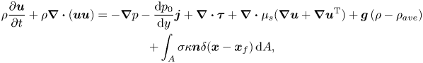 $$\begin{gather} \rho\frac{\partial \boldsymbol{u}}{\partial t} +{\rho} \boldsymbol{\nabla}\boldsymbol{\cdot}({\boldsymbol{u}}{\boldsymbol{u}}) =-\boldsymbol{\nabla}{p} -\frac{{\rm d}p_0}{{\rm d} y}\boldsymbol{j} +\boldsymbol{\nabla}\boldsymbol{\cdot}{\boldsymbol\tau} +\boldsymbol{\nabla}\boldsymbol{\cdot}\mu_s(\boldsymbol{\nabla}{{\boldsymbol{u}}}+\boldsymbol{\nabla}{{\boldsymbol{u}}^{\rm T}})+\boldsymbol{g}\left(\rho-\rho_{ave}\right) \nonumber\\ + \int_A \sigma\kappa\boldsymbol{n}\delta(\boldsymbol{x}-\boldsymbol{x}_f)\,{\rm d}A, \end{gather}$$
where  ${\boldsymbol {u}}$,
  $\boldsymbol {\tau }$,
  $p$,
$p$,  $\rho$,
  $\mu _s$ are the velocity vector, polymer stress tensor, pressure, discontinuous density and solvent viscosity fields, respectively. A constant pressure gradient
  $-({{\rm d}p_0}/{{\rm d} y})\boldsymbol {j}$ is applied to drive the flow where
  $\boldsymbol {j}$ is the unit vector in the
  $y$-direction. The buoyancy term consists of the gravitational acceleration
  $\boldsymbol {g}$ and the density difference
  $\rho -\rho _{ave}$, where
  $\rho _{ave}$ is the average density in the computational domain. The effect of surface tension is added as a body force term on the right-hand side of the momentum equation where
  $\sigma$ is the surface tension coefficient,
  $\kappa$ is twice the mean curvature and
  $\boldsymbol {n}$ is a unit vector normal to the interface. As the surface tension acts only on the interface,
  $\delta$ represents a three-dimensional Dirac delta function with the arguments
  $\boldsymbol {x}$ and
  $\boldsymbol {x}_f$ being a point at which the equation is evaluated and a point at the interface, respectively. The momentum equation is supplemented by the continuity equation
 \begin{equation} \boldsymbol{\nabla} \boldsymbol{\cdot} \boldsymbol{u} = 0. \end{equation}
It is assumed that the material properties remain constant following a fluid particle, i.e.
 \begin{equation} \frac{{\rm D}\rho}{{\rm D}t} =0,\quad \frac{{\rm D}\mu_s}{{\rm D}t} =0,\quad \frac{{\rm D}\mu_p}{{\rm D}t} =0,\quad \frac{{\rm D}\lambda}{{\rm D}t} =0, \end{equation}
where  ${{\rm D}}/{{\rm D}t}= {\partial }/{\partial t} + \boldsymbol {u}\boldsymbol{\cdot}\nabla$ is the material derivative. For a viscoelastic fluid,
  $\mu _p$ is the polymeric viscosity and
  $\lambda$ is the polymer relaxation time.
Using an indicator function ( $I$), the material properties are set in the entire computational domain as
 \begin{equation} \left. \begin{gathered} \rho =\rho_{o}I({\boldsymbol{x}},t)+\rho_i\left(1-I({\boldsymbol{x}},t)\right),\\ \mu_s =\mu_{s,o}I({\boldsymbol{x}},t)+\mu_{s,i}\left(1-I({\boldsymbol{x}},t)\right),\\ \mu_p =\mu_{p,o}I({\boldsymbol{x}},t)+\mu_{p,i}\left(1-I({\boldsymbol{x}},t)\right),\\ \lambda =\lambda_{o}I({\boldsymbol{x}},t)+\lambda_i\left(1-I({\boldsymbol{x}},t)\right), \end{gathered} \right\} \end{equation}
where the subscripts ‘ $i$’ and ‘
 $o$’ denote the properties of the particle and the bulk fluid, respectively. Since the fluid in the dispersed phase is Newtonian, the values of
  $\mu _{p,i}$ and
  $\lambda _i$ are set to zero. The indicator function is defined as
 \begin{equation} I({\boldsymbol{x}},t) = \left\{ \begin{array}{@{}ll} 1, & \text{in the bulk fluid}, \\ 0, & \text{in the particle}. \end{array} \right. \end{equation}
 Viscoelasticity of bulk liquid is modelled using the Giesekus model (Giesekus Reference Giesekus1982). This model is capable of capturing the elongation of individual polymer chains and the resulting shear-thinning behaviour of the viscoelastic fluid. In the Giesekus model, the polymer stress tensor  $\boldsymbol {\tau }$ evolves by
 \begin{equation} \boldsymbol{\tau} = \frac{\mu_p}{\lambda}(\boldsymbol {B} - \boldsymbol{I}), \end{equation}
where  $\boldsymbol {B}$ and
  $\boldsymbol {I}$ are the conformation and the identity tensors, respectively. The conformation tensor evolves by
 \begin{equation} \frac{\partial \boldsymbol{B}}{\partial t} + \boldsymbol{u}\boldsymbol{\cdot}\boldsymbol{\nabla}\boldsymbol{B} - \boldsymbol{\nabla}\boldsymbol{u}^{\rm T} \boldsymbol{\cdot} \boldsymbol{B} - \boldsymbol{B}\boldsymbol{\cdot}\boldsymbol{\nabla}\boldsymbol{u} = \frac{1}{\lambda} \left[(1-\alpha)\boldsymbol{I} + (2\alpha - 1)\boldsymbol{B} - \alpha\boldsymbol{B^2}\right], \end{equation}
where  $\alpha$ is the mobility factor representing the anisotropy of the hydrodynamic drag exerted on the polymer molecules. Due to the thermodynamic considerations,
  $\alpha$ is restricted to
  $0\le \alpha \le 0.5$ (Schleiniger & Weinacht Reference Schleiniger and Weinacht1991). When
  $\alpha = 0$, the Giesekus model reduces to the Oldroyd-B model.
At high Weissenberg numbers, these highly nonlinear viscoelastic constitutive equations become extremely stiff, which makes their numerical solution a challenging task. The problem is overcome by using the well-known log-conformation method where an eigen decomposition is employed to re-write the constitutive equation of the conformation tensor in terms of its logarithm (Izbassarov & Muradoglu Reference Izbassarov and Muradoglu2015; Izbassarov et al. Reference Izbassarov, Rosti, Ardekani, Sarabian, Hormozi, Brandt and Tammisola2018). The interested readers are referred to Fattal & Kupferman (Reference Fattal and Kupferman2005) for the detailed procedure.
The flow equations (3.1) and (3.2) are solved fully coupled with the Giesekus model equation (3.6). The momentum, continuity and viscoelastic constitutive equations are solved on a stationary staggered Eulerian grid. A QUICK scheme is used to discretize the convective terms in the momentum equations while second-order central differences are used for the diffusive terms. For the convective terms in the viscoelastic equations, a fifth-order WENO-Z scheme (Borges, Carmona & Costa Reference Borges, Carmona, Costa and Don2008) is used. A fast Fourier transform (FFT)-based solver is used for the pressure Poisson equation. Since the pressure equation is not separable due to variable density in the present multiphase flow, the FFT-based solvers cannot be used directly. To overcome this challenge, a pressure-splitting technique presented by Dong & Shen (Reference Dong and Shen2012) and Dodd & Ferrante (Reference Dodd and Ferrante2014) is employed. The fluid–fluid interface is tracked by using the Lagrangian marker points located at the vertices of a triangular surface mesh. The marker points move with the local flow velocity interpolated from the Eulerian grid. The surface tension is computed on the Lagrangian grid and transferred to the Eulerian grid to be added to the momentum equation as a body force in a conservative manner. The Lagrangian grid is restructured at every time step to keep the surface mesh nearly uniform, smooth and comparable to the Eulerian grid. The indicator function is computed based on the location of the interface using the standard procedure as described by Tryggvason et al. (Reference Tryggvason, Scardovelli and Zaleski2011), which requires a solution of a separable Poisson equation. The same FFT-based solver is used to compute the indicator function. Once the indicator function is computed, the material properties are set in each phase using (3.4), which results in a smooth transition of material properties across the interface. A predictor-corrector scheme is used to achieve second-order time accuracy as described by Tryggvason et al. (Reference Tryggvason, Bunner, Esmaeeli, Juric, Al-Rawahi, Tauber, Han, Nas and Jan2001). The details of this Eulerian–Lagrangian method can be found in the book by Tryggvason et al. (Reference Tryggvason, Scardovelli and Zaleski2011) and in the review paper by Tryggvason et al. (Reference Tryggvason, Bunner, Esmaeeli, Juric, Al-Rawahi, Tauber, Han, Nas and Jan2001), and the treatment of the viscoelastic model equations in Izbassarov & Muradoglu (Reference Izbassarov and Muradoglu2015) and Izbassarov et al. (Reference Izbassarov, Rosti, Ardekani, Sarabian, Hormozi, Brandt and Tammisola2018).
4. Results and discussions
We first examine the dynamics of a nearly spherical fluid particle under similar conditions as used by Li et al. (Reference Li, McKinley and Ardekani2015) for a solid particle, i.e.  $Re=18.9, El=0.05, Ca=0.01, \alpha =0$. The main difference in the present case is the slip at the particle interface. Note that this set of parameters is also designated as the baseline case in the present study to facilitate direct comparison with the results obtained for a solid particle by Li et al. (Reference Li, McKinley and Ardekani2015).
A peculiar feature of a viscoelastic fluid flow is the presence of normal stress differences, which are given by  $N_1 = \tau _{yy} - \tau _{zz}$ and
  $N_2 = \tau _{zz} - \tau _{xx}$ in the present scenario. In the absence of the shear-thinning effect (
 $\alpha =0$), the Giesekus model reduces to the Oldroyd-B model and the second normal stress difference (
 $N_2$) becomes zero. Thus,
  $\alpha >0$ is an essential condition to model a viscoelastic fluid that exhibits a non-zero second normal stress difference. The geometry of the channel also plays a significant role in the development of these stresses. Here,
  $N_1$ is found to be maximum in the highest shear region near the walls, and its value becomes minimum in the corners and at the centre. Ho & Leal (Reference Ho and Leal1976) argued that this particular distribution of
  $N_1$ in a four-wall channel is the primary reason for the accumulation of solid particles in the corner and centreline regions. When the second normal stress difference develops in a shear-thinning viscoelastic fluid, not only does the distribution of
  $N_1$ in the channel change, but its magnitude is also reduced due to enhanced inertial effects (Li et al. Reference Li, McKinley and Ardekani2015). Figure 1(a) shows the distribution of
  $N_2$ in the channel cross-section when there is a strong shear-thinning effect present in the flow, i.e.
  $\alpha =0.1$. Eight vortices generated due to this distribution of
  $N_2$ away from the particle are also depicted in figure 1(b). This particular distribution of
  $N_2$ affects the orientation of particle migration and the development of a secondary flow field around the particle. An asymmetric pattern of streamlines is shown in figure 1(a) above the particle once the particle reaches its equilibrium position near the wall. These effects on the lateral migration of a deformable particle are explored one by one in the subsequent sections.
4.1. Dynamics of particle migration
Simulations are first performed to examine the effects of the Weissenberg number, the capillary number, the initial position and the mobility factor on the lateral migration of a non-buoyant particle in the channel flow at the nominal Reynolds number  $Re = 18.9$ and
  $\beta =0.1$. Figures 2(a) and 2(b) show the evolution of particle displacement in the lateral (
 $z$) direction and the corresponding change in the particle deformation during its migration, respectively. In a Newtonian fluid, a nearly spherical particle slightly moves towards the channel wall under the effects of inertia and stabilizes near the wall where wall-induced repulsive force balances the lift force. When the ambient fluid is viscoelastic, modelled by Oldroyd-B (
 $\alpha = 0$), the same spherical particle moves towards the centre of the channel under the elastic effects just like a solid particle (Li et al. Reference Li, McKinley and Ardekani2015). It is observed that although the overall trend of fluid particle displacement in the Oldroyd-B fluid is similar to that of a solid particle, the fluid particle moves towards the centre of the channel at a much higher rate as shown in figure 2(c). Compared with a solid particle, a fluid particle experiences a smaller drag due to slip at the interface, which makes it more sensitive to the inertial and elastic effects. When the particle deformability is increased gradually by increasing the capillary number to
  $Ca = 0.05$ and
  $Ca = 0.1$ for the same Oldroyd-B fluid, the rate of particle migration towards the channel centre is slightly reduced. As the particle moves towards the low shear region (towards the centre), its deformability starts to reduce and the same effect is observed in its lateral velocity as well. The effects on particle velocity will be discussed in detail later in § 4.5. It is interesting to observe that, although the deformability-induced lift force is expected to push the particle towards the centre, it acts in the opposite direction at this Reynolds number and slows down the particle migration towards the centre of the channel. Evolution of streamwise and wall normal velocities of the spherical and the slightly deformable particle are shown in figure 3, where the constant contours of viscoelastic stress components of
  $\tau _{yz}$ and
  $\tau _{zz}$ are also plotted in the insets in the
  $yz$-cutting plane. As seen, not only the wall-normal velocity but also the streamwise velocity is reduced when the particle is made slightly deformed by increasing the capillary number to
  $Ca=0.1$, although the deformation is still modest, i.e.
  $\chi \approx 1.05$. The viscoelastic stress distribution is also markedly different in both cases. This extreme sensitivity is attributed to a similar mechanism that is responsible for a jump discontinuity in the rise velocity of a buoyancy-driven bubble (Bothe et al. Reference Bothe, Niethammer, Pilz and Brenn2022). A different manifestation of the same mechanism has also been observed in our earlier work (Naseer et al. Reference Naseer, Ahmed, Izbassarov and Muradoglu2023) as well. According to the theory proposed by Bothe et al. (Reference Bothe, Niethammer, Pilz and Brenn2022), polymer molecules are stretched by the flow as they pass over the particle and this stored elastic energy is released on its front/back hemisphere giving an additional pull/push to the particle depending on the flow conditions. The transition is expected to occur when the convective time scale is equal to the polymer relaxation time, i.e. the effective Weissenberg number is unity. In the present scenario, the effective Weissenberg number can be defined as
  $Wi_{eff}={\lambda }/{(R/u_{rel})}$, where
  $R$ is the particle radius and
  $u_{rel}$ is the slip velocity. For the nearly spherical particle, the effective Weissenberg number is computed as
  $Wi_{eff}= 0.92$ at
  $t^*=5.53$ which is close to the critical value of unity. As the particle is elongated in the streamwise direction in the deformable case, the effective radius (minor axis) becomes larger so the polymer molecules relax on the front part of the particle before reaching the equator, which thus increases the drag and slows down the particle migration velocity.
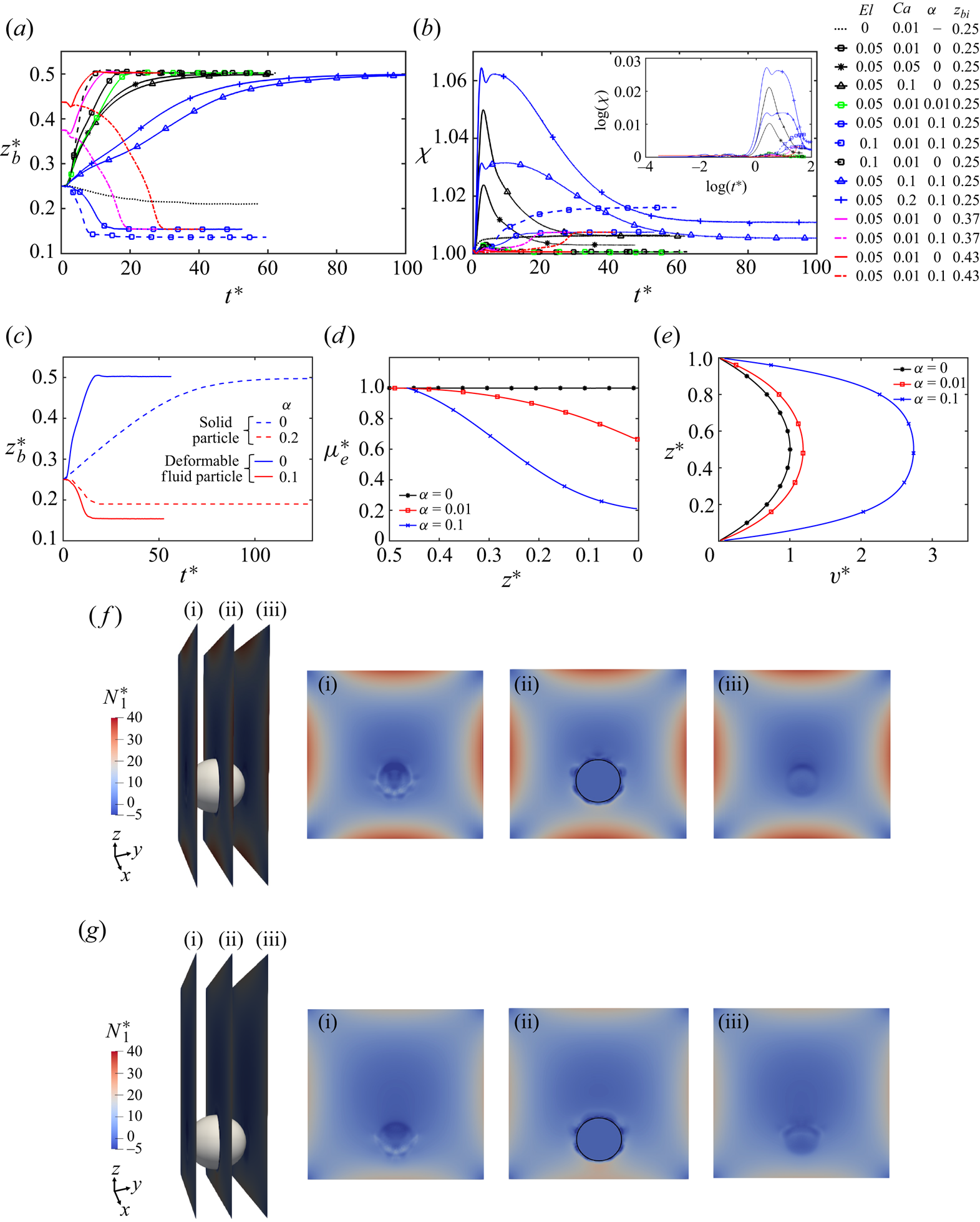
Figure 2. (a) Evolution of fluid particle displacement in the wall-normal ( $z$) direction under non-buoyant conditions for different initial positions and flow conditions. (b) Corresponding change in the particle deformation shown as the particle moves towards or away from the wall. The same plot is shown in the inset on a log-scale. (c) Evolution of the fluid particle displacement compared with a solid particle studied by Li et al. (Reference Li, McKinley and Ardekani2015) under similar flow conditions. (d) Reduction in the effective viscosity of the fluid due to shear thinning quantified in a vertical cutting
  $xz$-plane away from the particle. (e) Flow velocity profiles in the same
  $xz$-plane shown for different values of
  $\alpha$. The distributions of the first normal stress difference (
 $N_1$) around the particle are shown in vertical cutting planes of (i), (ii) and (iii) as indicated on the left for (f)
  $\alpha =0.01$ and for (g)
  $\alpha =0.1$. For panels (c–g),
  $El=0.05, Ca=0.01$. Additionally,
  $Re=18.9$ for all the cases presented in this figure.
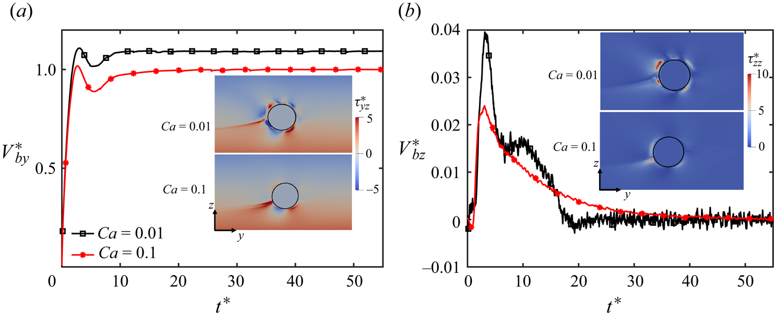
Figure 3. Evolution of migration velocity of a nearly spherical ( $Ca=0.01$) and a slightly deformed (
 $Ca=0.1$) fluid particle (a) in the streamwise and (b) in the wall-normal directions. The contours of viscoelastic stress components
  $\tau _{yz}$ and
  $\tau _{zz}$ are shown in the insets around the particles in the
  $yz$-cutting plane at
  $t^*=5.53$ (
 $Re=18.9, El=0.05, \alpha =0$).
When the shear-thinning effects are enhanced by increasing the mobility parameter ( $\alpha$) in the Giesekus model, the orientation of particle migration changes due to an increase in the relative importance of the fluid inertia. At a very small value of
  $\alpha =0.01$, a spherical particle still moves towards the centre but it takes a comparatively longer time than that in the Oldroyd-B fluid to reach its equilibrium position. Once
  $\alpha$ is increased further to
  $0.1$, the orientation of particle migration changes completely, i.e. instead of moving towards the centre, it starts moving towards the wall. Again, although the trend is similar to that of a solid particle in a shear-thinning fluid under the same parametric settings, the migration of a fluid particle is significantly more sensitive to the shear-thinning parameter than the corresponding solid particle. For example, while
  $\alpha = 0.2$ is required by the solid particle to reverse its orientation from the channel centre towards the wall (Li et al. Reference Li, McKinley and Ardekani2015),
  $\alpha =0.1$ is sufficient for the fluid particle to reverse its orientation. The shear-thinning effect is quantified by the reduction in the effective viscosity (
 $\mu _{e}$) of the fluid defined as
 \begin{equation} \mu_e/\mu_o = \frac{\mu_s\left(\dfrac{\partial v}{\partial z}+\dfrac{\partial w}{\partial y}\right)+\tau_{yz}}{\mu_o\left(\dfrac{\partial v}{\partial z}+\dfrac{\partial w}{\partial y}\right)}. \end{equation}
The variation of the effective viscosity and the corresponding flow velocity profiles are shown in figures 2(d) and 2(e), respectively, for  $\alpha =0$, 0.01 and 0.1. As seen, for
  $\alpha = 0$, the effective viscosity remains constant in the channel as expected. In a shear-thinning fluid (
 $\alpha >0$), the viscosity of the fluid decreases significantly in the high shear region near the wall and becomes as low as
  $20\,\%$ of its value in the channel centre for
  $\alpha =0.1$. As a result, the centreline flow velocity becomes approximately
  $2.8$ times larger than that of the non-shear-thinning fluid (figure 2e). This enhanced inertia helps the quick migration of the particle towards the wall as seen in figure 2(a). It is observed that this shear-thinning effect is strong enough to reverse the migration of fluid particle from the centre towards the wall even when the initial position of the particle is shifted gradually towards the channel centre, i.e. a low shear region (figure 2a). The shear thinning also changes the distribution of the first normal stress difference (
 $N_1$) in the channel. The distribution of
  $N_1$ is shown in three vertical cutting planes in the vicinity of the particle for
  $\alpha =0.01$ and
  $\alpha =0.1$ in figures 2(f) and 2(g), respectively, at the same time instant
  $t^*=5.71$. The higher magnitude of
  $N_1$ for
  $\alpha =0.01$ explains why the particle is pushed towards the channel centre. It is important to note that in the present study, as the channel aspect ratio is fixed (square duct only) and the initial position of the fluid particle is varied along one wall-normal direction (
 $z$) only while the initial position of the particle is fixed at
  $x=0.5H$ in the second wall-normal direction, the equilibrium positions of the fluid particle along the channel diagonals or in the corner regions are not observed (Yu et al. Reference Yu, Wang, Lin and Hu2019).
When the elasticity number is increased to  $El = 0.1$ by increasing the Weissenberg number in the presence of a strong shear-thinning effect (
 $\alpha =0.1$) for a spherical particle (
 $Ca = 0.01$), the viscoelastic stresses take more time to develop due to a higher relaxation time (
 $\lambda$) of polymer molecules. Therefore, the enhanced inertia due to the shear thinning quickly moves the particle towards the wall while the viscoelastic stresses are not yet fully developed in the flow. The particle reaches its equilibrium position closer to the wall and its deformation also increases due to a higher shear region there. However, this higher deformability and higher elasticity are not strong enough to reverse the particle migration back towards the channel centre. In the absence of the shear thinning (
 $\alpha =0$) with the same high elasticity number, the particle quickly moves towards the centre due to relatively lower inertia.
When the fluid particle is made more deformable by increasing the capillary number to  $Ca=0.1$ (figure 2b) in this shear-thinning fluid (
 $\alpha =0.1$), the deformability-induced lift force resists the pronounced effects of shear thinning on the fluid inertia. This higher particle deformation is sufficient enough to push the particle back towards the channel centre. However, due to the resistance by the higher inertial force, the rate of particle migration is much slower in this fluid than in the non-shear-thinning fluid. When the capillary number is increased even further to
  $Ca=0.2$, the effect is found to be more pronounced and the rate of particle migration towards the centre of the channel is slightly increased. The enhanced fluid inertia due to the shear-thinning effect also makes the particle more deformable in a shear-thinning fluid due to an effective high capillary number.
For all the simulations shown in figure 2, the nominal Reynolds number is kept constant. It can be observed that in this non-buoyant situation, the orientation of particle migration can be controlled with the shear-thinning effect of the viscoelastic fluid. With a strong shear-thinning effect ( $\alpha =0.1$), the particle moves towards the wall and higher elasticity (e.g.
  $El=0.1$) is not able to reverse its orientation. The higher particle deformability, however, resists this shear-thinning effect on particle migration and moves it back towards the centre. Interestingly, the particle deformation increases only by
  $6\,\%$ in the case of the maximum capillary number of
  $Ca=0.2$ in this viscoelastic fluid. However, even this modest deformation makes a significant impact on the dynamics of particle migration and reverses its orientation towards the centre. In the absence of shear thinning, the particle migrates towards the centre even with a weak elastic effect or with a little deformability.
4.2. Path instability
Path instability of a freely rising bubble in a Newtonian fluid has been thoroughly studied and well documented in the existing literature. For instance, Zenit & Magnaudet (Reference Zenit and Magnaudet2008) experimentally observed that the path instability of a bubble does not depend on the Reynolds number and it is rather governed by the aspect ratio of bubble shape, i.e. its deformation. When the aspect ratio increases beyond  $\chi > 2$, vortices generated on the free-slip surface of the bubble give rise to a wake instability behind the trailing edge, forcing its path to become unstable. In the case of a viscoelastic ambient fluid, Shew & Pinton (Reference Shew and Pinton2006) observed that the flow structure in the wake region becomes more intense leading to path instability even at a much lower deformability.
Simulations are first performed for  $Re=100$,
  $500$ and
  $1000$ to examine the effects of the Reynolds number on the path instability of the deformable fluid particle in the present pressure-driven viscoelastic flow in the absence of buoyancy. To isolate the effects of the Reynolds number, the shear-thinning effect is eliminated by setting
  $\alpha =0$, and the capillary number is fixed at
  $Ca=0.01$ to keep the particle nearly spherical. Simulations are repeated by keeping either the elasticity number or the Weissenberg number constant as the Reynolds number is increased. The results are summarized in figures 4(a,c) and 4(b,d) for the fixed elasticity number and the fixed Weissenberg number cases, respectively. When the elasticity number is kept constant at
  $El=0.05$ (figure 4a), the Weissenberg number increases as the Reynolds number is increased. The particle path becomes unstable at
  $Re=100$ (the corresponding
  $Wi=5$). However, the particle deformation remains negligible due to a low value of the capillary number. The path instability observed in this case of a nearly spherical particle at
  $Re=100$ occurs mainly due to the onset of an elastic flow instability caused by the curved streamlines along the particle interface. McKinley, Pakdel & Öztekin (Reference McKinley, Pakdel and Öztekin1996) determined a critical parameter for the onset of an elastic instability as
 \begin{equation} M^2=\frac{\lambda U}{R} \frac{N_1}{|\tau_t|} \ge M^2_{crit}, \end{equation}
where  $U$ is the flow velocity along the streamline,
  $N_1$ is the first normal stress difference,
  $R$ is the radius of curvature of the streamline and
  $\tau _t$ is the total shear stress. McKinley et al. (Reference McKinley, Pakdel and Öztekin1996) calculated the critical value for a two-dimensional cylinder as
  $M_{crit}\approx 6.08$. In the present scenario of a spherical fluid particle, the critical value turns out to be
  $M_{crit}\approx 5.59$ at
  $Re=100$. The constant contours of the Q-criterion (second invariant of velocity gradient tensor) at
  $0.001$ and the streamlines are also plotted around the particle in figure 4(c) for
  $Re=500$ to show the overall flow structure. The contours are coloured by the magnitude of vorticity in the
  $z$-direction. The curvature of streamlines across the particle and the contours of the Q-criterion confirm that the flow is no longer stable. As a result, the particle path shows an oscillatory pattern around the channel centre for
  $Re=100$. When the Weissenberg number is increased further by increasing the Reynolds number at the fixed value of
  $El=0.05$, figure 4(a) shows that the particle path becomes more irregular and unpredictable as the flow gets closer to the onset of elastic turbulence stemming from the elastic instability. The exact mechanism behind this probable transition is still elusive (Datta et al. Reference Datta2022).
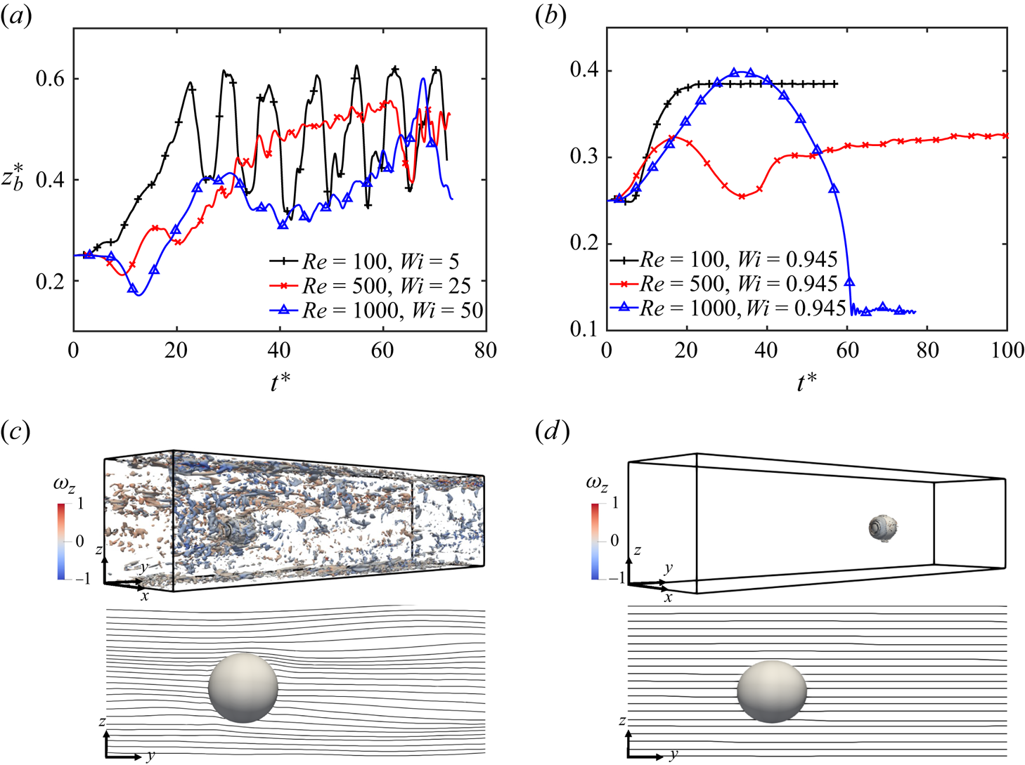
Figure 4. Evolution of lateral migration of the fluid particle (a) at constant  $El=0.05$ and (b) at constant
  $Wi=0.945$ are shown for different values of Reynolds number. (c) Constant contours of Q-criterion at
  $0.001$ coloured by the vorticity component (
 $\omega _z$) shown for
  $Re=500, Wi=25$ as the flow becomes elastically unstable due to the curvature of streamlines across the particle. (d) Contours of Q-criterion plotted at the same value of
  $0.001$ for
  $Re=500, Wi=0.945$ showing a negligible presence, confirming a stable flow. This is also confirmed by the straight streamlines across the fluid particle.
However, when the Weissenberg number is kept constant at  $Wi=0.945$ as
  $Re$ is increased, the particle path remains stable even for the Reynolds number as high as
  $Re=1000$. As shown in figure 4(d), the streamlines remain straight across the particle and no significant contours of Q-criterion are observed in the flow, unlike the fixed elasticity number case. It is interesting to observe that the particle initially moves towards the channel centreline and then reverses its direction towards the channel wall at higher Reynolds numbers. The final position is determined by the interplay of inertial and viscoelastic effects. The equilibrium position of the particle shifts from the channel centre towards the wall as the Reynolds number is increased (figure 4b). At
  $Re=1000$, the particle reaches the wall under the influence of strong inertia, which results in an increase in its deformation as well due to the high-shear region near the wall.
4.3. Effect of buoyancy
The buoyancy is significant in many natural processes and practical applications. A commonly encountered situation is an upward flow where the gravity acts in the opposite direction of the fluid flow such as in bubble column reactors and in crude oil extraction. Simulations are next performed for a range of Eötvös numbers to examine the effects of buoyancy in an upward flow while keeping the other parameters fixed at their baseline values of  $Re=18.9$,
  $Ca=0.01$ and
  $El=0.05$. Note that the Morton number is
  $M=4.97 \times 10^{-6}$ for
  $Eo = 1$ in this viscoelastic fluid. For reference, this value is much higher than the Morton number of
  $2.52 \times 10^{-11}$ for an air particle in water at
  $20\,^\circ$C but can be matched by using a water–glycerin solution (Legendre, Zenit & Velez-Cordero Reference Legendre, Zenit and Velez-Cordero2012).
Simulations are performed by gradually increasing the Eötvös number from  $Eo=0$ (neutrally buoyant) to
  $Eo=1$ without and with the shear-thinning effect. The case of
  $Eo=0$ is simulated by setting
  ${\boldsymbol g}=0$, which can be realistic only in a microgravity environment. This condition is used here to isolate the sole effects of the other parameters from buoyancy. The results are shown in figures 5(a,c,e,g) and 5(b,d,f,h) in terms of the evolution of particle deformation, its three-dimensional displacement, the wake structure behind the particle, and the pressure distribution on the particle surface for an Oldroyd-B (
 $\alpha =0$) and a Giesekus (
 $\alpha =0.1$) fluid case, respectively. In the Oldroyd-B fluid, the particle moves towards the channel wall without any sign of path instability at
  $Eo=0.25$. We note that the same particle moves towards the channel centre in the absence of buoyancy. This change in the orientation occurs due to the additional buoyancy-induced lift force (Lu, Biswas & Tryggvason Reference Lu, Biswas and Tryggvason2006). At
  $Eo=0.5$, the particle still migrates towards a channel wall (interestingly not to the same wall as in the
  $Eo=0.25$ case) but small oscillations start to appear in its path with a regular zigzag pattern indicating the onset of a path instability. A similar oscillatory pattern is also visible in the particle deformation (
 $\chi$) as seen in figure 5(a). When
  $Eo$ is further increased to
  $0.75$, the particle deformation also increases and the particle path shifts from a zigzag to a helical pattern. The particle moves laterally to eventually settle near the other side of the channel and its motion becomes more chaotic with a significant velocity component in the wall normal (
 $x$) direction. At
  $Eo=1$, the particle path becomes completely unstable with a deformation parameter (
 $\chi$) exceeding
  $1.6$ (figure 5a).
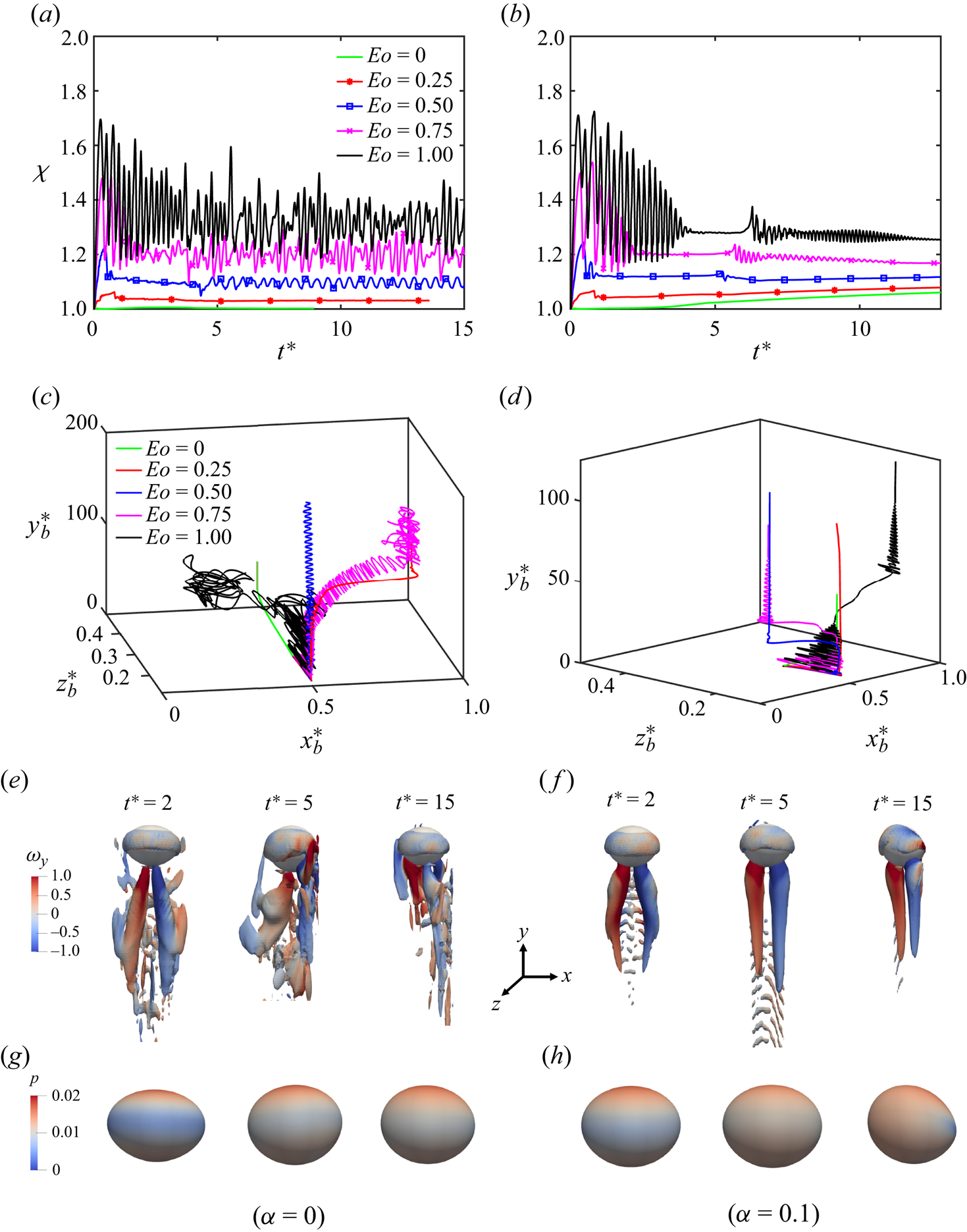
Figure 5. Evolution of particle deformation and its three-dimensional (3-D) displacement at different values of Eötvös number are shown for (a,c)  $\alpha =0$ and for (b,d)
  $\alpha =0.1$. For the
  $Eo=1$ case, the constant contours of the Q criterion at
  $0.05$ are shown to visualize the complex flow pattern in the wake region behind the particle for (e)
  $\alpha =0$ and for (f)
  $\alpha =0.1$. The contours are coloured by vorticity (
 $\omega _y$) in the range of
  $\pm 1$. For the same
  $Eo=1$ case, the pressure distribution on the particle surface are shown at the same times for (g)
  $\alpha =0$ and for (h)
  $\alpha =0.1$. (
 $Re=18.9, Ca=0.01, El=0.05, \beta =0.1$.)
It is worth noting that the deformation parameter is only approximately  $\chi =1.1$ when the deformed particle undergoes path instability at
  $Eo=0.5$ in the present setting. This value is much smaller than the condition
  $\chi \ge 2$ required for the onset of a path instability in the case of a freely rising bubble in a Newtonian fluid (Zenit & Magnaudet Reference Zenit and Magnaudet2008). This result confirms that the viscoelasticity facilitates the earlier onset of path instability as also pointed out by Shew & Pinton (Reference Shew and Pinton2006). The wake region is much more intense in the viscoelastic fluid than in the Newtonian fluid due to the additional viscoelastic stresses, forcing its path to become unstable at a relatively small deformation. The evolution of the wake region and the corresponding pressure distribution on the particle surface is depicted for the
  $Eo=1$ case in figures 5(e) and 5(g), respectively, to qualitatively show the mechanism for the path instability. As seen, the structure of the wake is highly complex and transient, and the pressure distribution changes accordingly, indicating the footprint of the instability.
Next, a strong shear-thinning effect is added ( $\alpha =0.1$), and the simulations are repeated for the same values of
  $Eo$ by keeping the other parameters fixed at their baseline values of
  $Re=18.9$,
  $El=0.05$ and
  $Ca=0.01$. The results are summarized on the right-hand side of figure 5. As seen in figure 5(d), the particle migrates towards a wall for all the cases but interestingly not to the same wall. The path of the fluid particle remains stable for
  $Eo=0.25$ but it migrates towards the wall at a much higher rate than that for the non-buoyant case of
  $Eo=0$. This behaviour is attributed to the same enhanced lift force due to the buoyancy as in the non-shear-thinning case. Some oscillations appear in the particle trajectory for
  $Eo=0.5$ but they are damped very quickly as the particle stabilizes near a wall. As
  $Eo$ is increased beyond
  $Eo=0.5$, the oscillations are amplified leading to path instability. For
  $Eo=0.75$, the particle migrates laterally and settles near the other wall similar to the Oldroyd-B fluid case. In this case, the particle initially follows a helical path but, interestingly, its path is stabilized after some time (figure 5d). The corresponding oscillatory pattern observed in the deformation also vanishes once the particle path is stabilized (figure 5b). The stabilized particle path is also observed for
  $Eo=1$. The stabilization mechanism is visualized in figure 5(f) where the evolution of the wake structure is depicted for the
  $Eo=1$ case. As seen, the wake behind the particle is not symmetric initially but it later evolves into a symmetric two counter-rotating vortex structures indicating that the path is stabilized. Two contributory factors are speculated to be the main reason for this stabilization mechanism. First, with a decrease in fluid viscosity in the vicinity of the particle due to the shear-thinning effect, the vortices generated on the surface of the deformed particle are not strong enough to make the wake region unstable. Second, due to the shear thinning of the fluid, the first normal stress difference
  $N_1$ decreases in this viscoelastic fluid, which reduces the destabilization effect of viscoelasticity. Thus, the intense flow structures observed in the wake region in the case of the Oldroyd-B fluid (figure 5e) are damped out in this shear-thinning fluid (figure 5f). Although an addition of shear thinning makes the particle path more stable, it cannot maintain path stability indefinitely. For instance, although not shown here due to space consideration, once the particle deformation exceeds
  $\chi >2$ at
  $Eo=2$, the path remains unstable even for the mobility factor as high as
  $\alpha =0.1$.
All the simulations have heretofore been performed for a small value of the viscosity ratio,  $\beta =0.1$, representing highly concentrated polymer solutions. Thus, the fluid exhibited a strong viscoelastic behaviour and the particle path remained stable only up to
  $Eo=0.25$ and
  $Eo=1$ without and with the shear-thinning effect, respectively. To examine the particle migration dynamics in dilute polymer solutions, simulations are now performed for another extreme value of
  $\beta = 0.9$ without and with the shear-thinning effect. It is important to note that
  $\beta =0.9$ represents a very rare case that can be achieved only with specially designed fluids. Figure 6(a,b) show the evolution of lateral displacement of a particle and its deformation for the range of
  $2\le Eo \le 8$. We note that at the lower values of
  $Eo$ up to
  $Eo=2$, there is not much difference observed in the particle deformation and its equilibrium position compared with the case of
  $Eo=2$ in figure 6(a). As
  $Eo$ increases, the difference in the equilibrium position of the particle becomes increasingly more pronounced without and with the shear-thinning effect. For the smaller values of Eötvös number up to
  $Eo=2$, the shear-thinning effect does not play a dominant role due to a lower value of particle deformation. As the contribution of polymeric viscosity towards the total viscosity of the fluid is already very low at
  $\beta =0.9$, a further decrease in the viscosity due to shear thinning starts to show its effect only at a higher value of particle deformation. Beyond
  $Eo=2$ and with
  $\alpha =0.1$, the particle reaches the channel centre for all the values of
  $Eo$ up to
  $Eo=8$, whereas without the shear-thinning effect, the equilibrium position of the particles occurs slightly away from the centre depending upon its deformation. The most interesting feature is the persistent stability of the particle path even when the deformation exceeds
  $2.3$ for the
  $Eo=8$ case (figure 6b inset). Zenit & Magnaudet (Reference Zenit and Magnaudet2008) have shown that for a freely rising bubble, the path becomes unstable when the deformation value exceeds
  $2$. They argued that for such a buoyancy-driven bubble, path instability depends upon the bubble deformation rather than the Reynolds number. However, Haberman & Morton (Reference Haberman and Morton1953) and Kelley & Wu (Reference Kelley and Wu1997) had earlier demonstrated that the path instability of an air bubble in a viscous fluid of a Hele-Shaw cell did depend on the Reynolds number. It is found that the criterion,
  $\chi > 2$, for triggering path instability does not apply in the present case of a pressure-driven viscoelastic channel flow at this low Reynolds number.
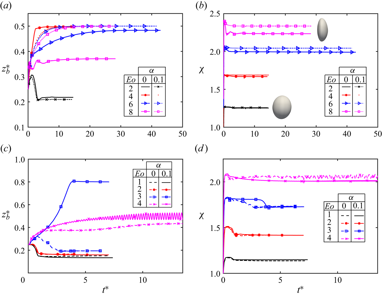
Figure 6. (a) Evolution of particle displacement in the lateral ( $z$) direction and (b) its deformation for different values of Eötvös number. For panels (a,b),
  $Re=18.9, Ca=0.01, El=0.05, \beta =0.9$. For panels (c,d),
  $Re=47.25, Ca=0.01, El=0.02, \beta =0.9$. The shapes of the deformed fluid particles are shown in the inset of panel (b) for
  $\alpha =0$ case at
  $Eo=2$ and
  $Eo=8$.
To verify the dependence of path instability of the fluid particle on the Reynolds number, simulations are next performed by increasing the Reynolds number to  $47.25$ while keeping the Weissenberg number fixed at
  $Wi=0.945$. As a result, the elasticity number is reduced to
  $0.02$. Simulations are repeated for
  $\alpha = 0$ (no shear thinning) and
  $\alpha = 0.1$ (significant shear thinning) cases for the range of Eötvös number
  $1\le Eo \le 4$. Figure 6(c,d) depict the evolution of particle displacement in the lateral direction and its deformation. As
  $Eo$ increases, the particle deformation also increases and its equilibrium position gradually shifts away from the wall. At
  $Eo=3$, as the fluid viscosity decreases in the vicinity of the particle, the elastic effect becomes dominant and the particle migrates towards the channel centre. The particle crosses the channel centre under the combined effects of deformation-induced lift force and the fluid elasticity, and settles at an equilibrium position closer to the wall on the other side of the channel as the inertial effects eventually dominate (figure 6c). However, without shear thinning, the particle migrates towards the wall as the deformation and elasticity are not strong enough to counter high inertial lift force at
  $Eo=3$. Interestingly, both the particles settle at the same equilibrium position closer to the wall but on the opposite sides of the channel.
At  $Eo=4$, when the particle deformation exceeds
  $2$ and the shear-thinning effect is present, small oscillations start to appear in its path indicating the onset of a path instability. It shows that path instability of the fluid particle in this pressure-driven viscoelastic flow is a function of Reynolds number as well along with the particle deformation. It is also observed that the particle path remains stable in the absence of shear thinning (
 $\alpha =0$) at the same value of
  $Eo=4$. Interestingly, this role of shear thinning is opposite to what was observed in the case of
  $\beta = 0.1$, i.e. the shear thinning damps out the path instability at low values of
  $\beta$ (high polymer concentration) whereas it promotes the path instability of the particle at high
  $\beta$ values (dilute polymer concentration). This interesting behaviour is attributed to the local change in the effective elasticity number (
 $El$) due to the shear-thinning effect. Ray & Zaki (Reference Ray and Zaki2014) have shown that, for larger values of
  $El$, there is an asymptotic limit of stabilization observed in the Oldroyd-B model. We find that this role of elasticity number in stabilizing or destabilizing the particle path is further dependent upon the value of
  $\beta$. At lower
  $\beta$, a decrease in the local value of
  $El$ stabilizes the particle path while, at the higher value of
  $\beta$, the same decrease in
  $El$ is found to be destabilizing.
4.4. Particle-induced secondary flow
The presence of the second normal stress difference ( $N_2$) and the geometry of the square-shaped channel induces a secondary flow field in a direction perpendicular to the primary flow. The dynamics of this secondary flow field is significantly influenced by the presence of a fluid particle. Moreover, the orientation of particle migration also affects the magnitude of the secondary flow velocity. The secondary flow velocity has been analysed by varying the particle deformability (
 $Ca$), the shear thinning (
 $\alpha$), the fluid elasticity (
 $Wi$) and the fluid inertia (
 $Re$). Figure 7 shows complex flow patterns in vertical cutting planes at the downstream, the centre and upstream of the particle under different flow conditions. The upstream and downstream planes are located at
  $+0.75$ and
  $-0.75$ from the particle centre, respectively. The velocity vectors are coloured by the magnitude of flow velocity in the
  $xz-$plane. In an Oldroyd-B fluid, the particular distribution of
  $N_1$ in the channel far away from the particle builds up a weak secondary flow oriented towards the corners of the channel from its centre. It generates a ‘flower-shaped’ flow pattern as shown in figure 7(a). The presence of
  $N_2$ due to the shear-thinning effect (Giesekus fluid) generates an additional eight vortices at the corners of the channel (figure 7d). Once the particle passes through this plane and migrates towards the centre (figure 7g,h), this flow pattern gets disturbed but becomes symmetric again above and below the particle once the particle attains its steady-state position. However, if the particle migrates towards a channel wall, the flow pattern becomes highly asymmetric away from the wall resulting in a strong secondary flow with a velocity as high as the order of particle migration velocity (figure 7k).
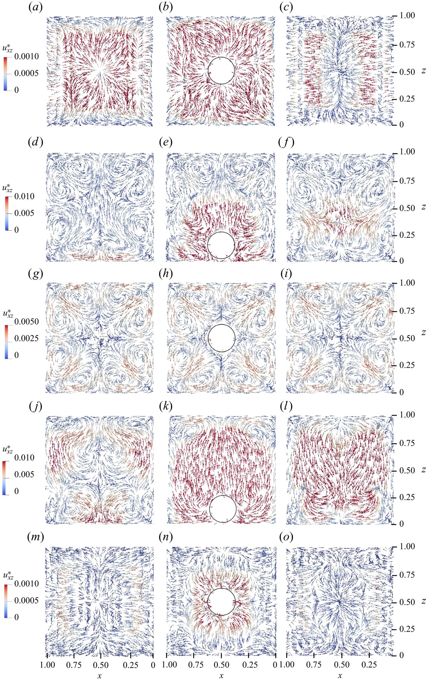
Figure 7. Velocity vectors representing the complex flow patterns of secondary flow field in vertical cutting planes at (a,d,g,j,m) a downstream, (b,e,h,k,n) the centre and (c,f,i,l,o) upstream of the particle. (a–c)  $Re=18.9, Ca=0.01, El=0.05, \alpha =0$. (d–f)
  $Re=18.9, Ca=0.01, El=0.05, \alpha =0.1$. (g–i)
  $Re=18.9, Ca=0.2, El=0.05, \alpha =0.1$. (j–l)
  $Re=18.9, Ca=0.01, El=0.1, \alpha =0.1$. (m–o)
  $Re=18.9, Ca=0.1, El=0.05, \alpha =0$.
The quantitative comparison of secondary flow velocities is summarized in figure 8 for different flow conditions. The  $z$-component of flow velocity is numerically integrated in the region
  $\pm 0.75$ upstream and downstream of the particle in the streamwise (
 $y$) direction and the integration is performed in the entire domain [
 $0 , 1$] in the
  $z$-direction, i.e.
 \begin{equation} \langle u_z\rangle_{y,z}=\frac{1}{A_{yz}}\int_0^1\int_{-0.75}^{+0.75}u_z \,{\rm d}z\,{\rm d}y \cong \frac{1}{\left(j_{max}-j_{min}+1\right) N_z}\sum_{k=1}^{N_z}\sum_{j=j_{min}}^{j_{max}}(u_z)_{jk}, \end{equation}
where  $A_{yz}$ is the area of the
  $yz$-plane, and
  $j_{min} = (y_b-0.75)N_y/L$ and
  $j_{max} = (y_b+0.75)N_y/L$ with
  $N_y$ and
  $N_z$ being the number of grid points in the
  $y$ and
  $z$ directions, respectively. The average secondary velocity,
  $\langle u_z \rangle _{y,z}$, in the
  $y$ and
  $z$ directions is plotted along
  $x$ in figure 8 once the particle reaches its equilibrium position closer to a wall or towards the centre of the channel. Figure 8(a,b) show the average secondary flow velocity for
  $Re=18.9$ while the results for higher Reynolds numbers are shown in figure 8(c,d).
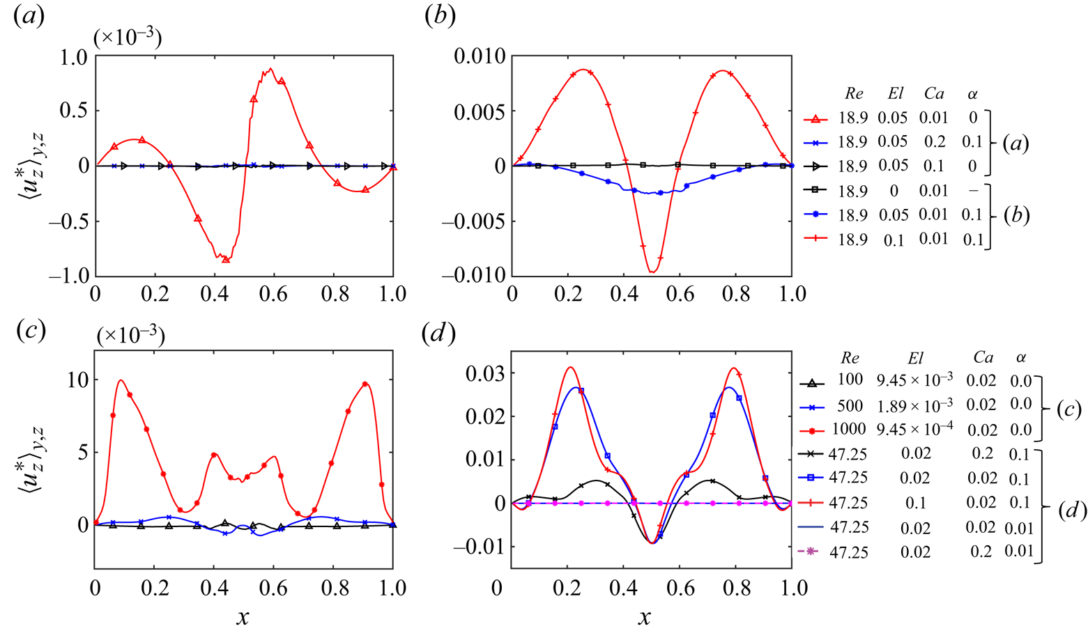
Figure 8. Averaged secondary flow velocity under the flow conditions (a) where the fluid particle migrates towards the channel centre and (b) where the particle migrates towards a wall at  $Re=18.9$. The averaged secondary flow velocity is plotted for higher Reynolds numbers in the range
  $47.25\leq Re \leq 1000$ for (c) an Oldroyd-B fluid and (d) a Giesekus fluid.
At  $Re=18.9$, the magnitude of the secondary flow velocity remains negligible for all the situations where the particle migrates towards the channel centre (figure 8a). In an Oldroyd-B fluid, the particle migrates towards the centre of the channel under the effect of elasticity, as shown in figure 2. As the particle migrates in the
  $z$-direction and reaches the centre, the flow pattern becomes symmetric above and below the particle (figure 7b). In a Giesekus fluid, when the shear-thinning effect is sufficient enough to move the particle towards a wall (
 $\alpha =0.1$), a strong secondary flow pattern is observed as shown in figure 8(b). When the elasticity number is increased in this shear-thinning fluid, the maximum magnitude of the secondary flow velocity is attained. This is the same combination of parameters for which the particle equilibrium position is closest to the channel wall in figure 2(a). The flow pattern above the particle for this situation is depicted in figure 7(k). When the Reynolds number is increased in an Oldroyd-B fluid, the equilibrium position of the particle moves closer to the channel wall. When the Weissenberg number is kept constant while increasing the Reynolds number to avoid elastic instability, as discussed in § 4.2, the magnitude of the secondary flow velocity keeps increasing with the Reynolds number and becomes as high as
  $1\,\%$ of the maximum flow velocity in the channel (figure 8c). A small asymmetry observed in the secondary flow pattern for the
  $Re=1000$ case is attributed to the slight migration of the particle in the
  $x$-direction due to onset of an inertial path instability.
At  $Re=47.25$, when the shear-thinning effect is small (
 $\alpha = 0.01$), the particle moves towards the centre of the channel whether it is spherical (
 $Ca=0.01$) or highly deformable (
 $Ca=0.1$). The secondary flow velocity remains negligible for both of these situations (figure 8d). However, this time, the magnitude of the secondary flow velocity depends on the particle deformability along with the fluid elasticity. When the particle deformability is increased, the magnitude of the secondary flow velocity is reduced whereas an increase in the fluid elasticity (
 $Wi$) further increases its magnitude. Thus, a nearly spherical particle migrating towards the channel wall induces maximum secondary flow due to the maximum asymmetric area of influence above. This area reduces with the particle deformability and hence a reduction in the induced secondary flow is observed. Similarly, a higher magnitude of viscoelastic stresses due to higher
  $Wi$ generates a complex flow pattern in the direction normal to the primary flow. This flow pattern becomes increasingly more asymmetric with increasing
  $Wi$ and as a result, the secondary flow velocity becomes as high as
  $3\,\%$ of the maximum flow velocity in this square channel (figure 8d).
It can be summarized that an increase in the fluid elasticity ( $Wi$) or inertia (
 $Re$) increases the magnitude of the secondary flow velocity as long as the particle moves towards a wall. If the flow conditions are such that the particle moves towards the channel centre, an increase in the inertia or elasticity of the fluid makes negligible impact on the velocity of the secondary flow once the particle reaches its steady-state position. However, during the transient period while the particle is still migrating towards the centre, the inertia and fluid elasticity do make an impact on the velocity of the secondary flow but its magnitude during this transient period remains two orders of magnitude lower than the corresponding cases where the particle migrates towards the wall.
It is important to note that the secondary flow velocity induced by a fluid particle is at least an order of magnitude higher than the velocity induced by the solid particle under the similar flow conditions as reported by Li et al. (Reference Li, McKinley and Ardekani2015). The primary reason is the higher drag experienced by the solid particle due to the no-slip condition on its surface. This attribute of fluid particle-induced secondary flow can be exploited in the situations where mixing, heat transfer or other transport phenomena are of importance.
4.5. Flow start-up
It is a well-known aspect that stress waves propagate (Duarte, Miranda & Oliveira Reference Duarte, Miranda and Oliveira2008) and cause velocity fluctuations during flow build-up in a channel flow. The elasticity of the fluid affects these fluctuations depending upon the relaxation time of its polymer molecules. In our earlier work (Naseer et al. Reference Naseer, Ahmed, Izbassarov and Muradoglu2023), these velocity fluctuations were also observed in the rise velocities of freely rising bubbles in a viscoelastic fluid. Similarly, these velocity fluctuations affect the migration velocity of the solid particle as well during the flow build-up (Rajagopalan, Arigo & McKinley Reference Rajagopalan, Arigo and McKinley1996). Goyal & Derksen (Reference Goyal and Derksen2012) have shown that a solid particle settling down during these fluctuations often rebounds after the first oscillation. In the present study, we explore the same effects for a fluid particle in this viscoelastic channel flow.
Figure 9(a) shows the migration velocity of the particle in the wall-normal direction ( $z$) under various flow conditions. The two cases are shown in the inset where the particle is highly deformable (
 $Ca=0.1$ and
  $Ca=0.2$) and it takes a comparatively longer time to reach a steady state. Figure 9(b) shows the evolution of the average streamwise component of flow velocity in the channel for the same nine situations. In the case of a nearly spherical particle (low
  $Ca$) migrating in an Oldroyd-B fluid (
 $\alpha = 0$), the elastic stresses develop quickly in the flow and take the particle towards the centre. As
  $N_1$ decreases in the low-shear region near the centre, the particle reaches its peak velocity at
  $t^* \approx 4$ and then starts to decelerate while continuing its migration towards the centre. The minor fluctuations in the particle velocity are attributed to the extension/relaxation of polymer molecules across its surface as recently explained by Bothe et al. (Reference Bothe, Niethammer, Pilz and Brenn2022) and verified by Naseer et al. (Reference Naseer, Ahmed, Izbassarov and Muradoglu2023). A minor decline in the flow velocity is observed after an initial peak once the viscoelastic stresses are developed in the flow (figure 9b). When the particle deformability is increased (
 $Ca=0.05$ and
  $Ca=0.1$), the particle starts migrating towards the channel centre. However, due to a slight increase in its deformability, the peak velocity of the particle migration remains lower than that of the nearly spherical particle. When a spherical particle (
 $Ca=0.01$) migrates in the Giesekus fluid having a very low shear thinning (
 $\alpha =0.01$), migration towards the channel centre occurs primarily due to the elastic effects and similar fluctuations are observed in the migration velocity as in the case of Oldroyd-B fluid. As the shear thinning promotes the relative importance of fluid inertia which acts to pull the particle back towards the wall, the peak velocity of the particle remains lower than that in the Oldroyd-B fluid. The average flow velocity is slightly increased in the channel due to the shear-thinning effect and the actual effective Reynolds number becomes
  $Re_{eff}=22.4$. When the shear-thinning effect is high enough (
 $\alpha = 0.1$), the enhanced fluid inertia overcomes the elastic effects and causes the particle to migrate towards the wall, as indicated by the opposite direction of particle velocity in figure 9(a). The flow velocity in the channel increases further and the effective Reynolds number reaches
  $51.8$ with the same value of an applied pressure gradient. When the elasticity number is increased (
 $El=0.1$) by increasing the polymer relaxation time in this shear-thinning viscoelastic fluid, the inertial effects still dominate and push the particle towards a wall at a higher rate. With increased viscoelastic stresses at higher
  $El$ and a strong shear-thinning effect, the effective Reynolds number reaches
  $92$. With the same high elasticity number (
 $El=0.1$) but without shear thinning (
 $\alpha = 0$), the particle migrates towards the centre under the elastic effects. Due to a higher Weissenberg number, the viscoelastic stresses become comparatively stronger and the particle reaches a higher value of its migration velocity. As there is no shear-thinning effect, the flow Reynolds number remains at the baseline value of
  $Re=18.9$.
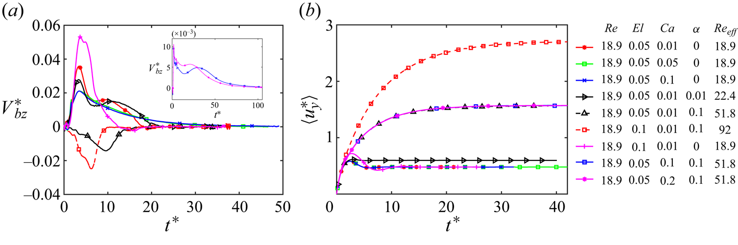
Figure 9. (a) Evolution of particle migration velocity in the wall-normal ( $z$) direction during flow start-up. (b) Evolution of average steamwise component of flow velocity in the channel.
Once the particle is made highly deformable ( $Ca=0.1$ and
  $Ca=0.2$) and the fluid is strongly shear thinning (
 $\alpha =0.1$), the ‘deformability-induced’ lift force overcomes the shear-thinning enhanced inertial effects and the particle moves towards the channel centre. As the particle gets closer to the centre, its deformability starts reducing due to low shear (as shown in figure 2b) resulting in a deceleration in its lateral migration velocity. It is worth noting that the effective flow Reynolds number becomes
  $Re_{eff} = 51.8$ due to a strong shear-thinning effect in this case.
5. Conclusions
Interface-resolved numerical simulations are performed to explore the complex dynamics of cross-stream migration of a fluid particle in a viscoelastic pressure-driven channel flow for a wide range of flow parameters. Unlike the solid particle, the deformability of the fluid particle, the slip condition at the interface and the particle-induced elastic flow instability at a higher Weissenberg number add further complexity to this phenomenon. The particle deformability ( $Ca$), shear thinning of the ambient fluid (
 $\alpha$), fluid elasticity (
 $Wi$), buoyancy (
 $Eo$) and concentration of polymers (
 $\beta$) are varied one by one to isolate their sole effects. The conditions for triggering a path instability of a deformable particle in this pressure-driven viscoelastic flow are investigated and the particle-induced secondary flow is quantified.
It is observed that the forces induced by fluid inertia push the particle towards the wall while elasticity and deformability pull it towards the channel centre. This interplay between fluid inertia, elasticity and particle deformability determines the orientation of particle migration in the channel and its final equilibrium position. As shear thinning increases the relative importance of the fluid inertia, it is found to promote migration towards a wall. At a high Weissenberg number, elastic instability occurs due to the curvature of streamlines across the particle. When the Reynolds number is increased while keeping the Weissenberg number fixed at a low value, the particle path remains stable even for the Reynolds number as high as  $Re=1000$.
In the case of a high polymer concentration (e.g.  $\beta =0.1$), it is found that strong viscoelastic effects make the particle path unstable even when the particle is nearly spherical. This path instability occurs as the flow itself becomes elastically unstable at a higher value of
  $Wi$. In the absence of strong viscoelastic stresses (low
  $Wi$), the path of the particle becomes unstable when its deformation becomes high due to high
  $Eo$. However, the shear thinning acts as a stabilizing factor and can make the particle path stable even for the particle deformation as large as
  $\chi = 2$. The stabilizing role of shear thinning is reversed at higher values of
  $\beta$. When the Reynolds number is small and
  $\beta =0.9$, the particle path remains stable even for the Eötvös number as large as
  $Eo=8$ and its deformation exceeds
  $\chi > 2.3$. Thus, the path instability of a deformable particle in a viscoelastic pressure-driven channel flow can occur when the flow itself becomes elastically unstable at high
  $Wi$ or when its deformation exceeds a threshold value under buoyant conditions. If the path instability is triggered by the later mechanism, i.e. when the particle deformation exceeds a critical value, the shear thinning suppresses the path instability at higher polymer concentration (lower
  $\beta$) while it reverses its role and promotes the path instability at lower polymer concentration (higher
  $\beta$). Furthermore, it is found that the threshold value of particle deformation to trigger path instability is a function of Reynolds number as well in this pressure-driven viscoelastic flow unlike the path instability of a freely rising bubble in a Newtonian flow (Zenit & Magnaudet Reference Zenit and Magnaudet2008).
It is shown that the secondary flow velocity induced by a fluid particle migrating towards the wall is an order of magnitude higher than the one induced by a solid particle under similar flow conditions. This behaviour is attributed to the slip condition on the particle surface and the internal flow. For all the situations where the fluid particle migrates towards the centre, the secondary flow velocity becomes negligible due to the symmetric flow pattern above and below the particle when viewed in its migrating plane.
During the flow build-up in this square-shaped channel, the maximum value of flow velocity depends upon the shear-thinning property of the fluid. The particle migration velocity is dictated by the inertial effects and the rate at which the viscoelastic stresses are built up in the flow.
Supplementary movie
A time-lapse movie showing the generation and growth of instabilities in the flow at a high Weissenberg number ( $Re=500, Wi=25$) due to the presence of a deformable particle can be accessed at https://doi.org/10.1017/jfm.2024.583.
Funding
We acknowledge financial support from the Scientific and Technical Research Council of Turkey (TUBITAK; grant number 119M513) and the Research Council of Finland (grant number 354620).
Declaration of interests
The authors report no conflict of interest.
Data availability
Data can be made available upon request.
Appendix
A comprehensive grid convergence study is performed to ascertain the numerical accuracy of the results reported in this study. Figure 10(a) shows the evolution of particle displacement in the wall-normal ( $z$) direction plotted at three different grid resolutions. Linear least-squares fits at
  $t^* = 1.38, 4, 6$ and
  $8$ are shown in the inset of figure 10(a) where the approximately linear relations confirm the expected second-order spatial accuracy of the numerical scheme. These results show that a grid resolution containing
  $160 \times 320 \times 160$ grid cells in the
  $x$,
$x$,  $y$, and
  $z$ directions, respectively, is sufficient to reduce the spatial error below
  $3.5\,\%$. Therefore this grid resolution is used in all the simulations reported in this paper. Note that, for this grid resolution, there are about
  $40$ grid points in the
  $x$ and
  $z$ directions and
  $20$ grid points in the streamwise (
 $y$) direction per particle diameter. Figure 10(b) shows the evolution of average flow velocity in the channel and the linear least-square fits shown in its inset confirm that the numerical error remains negligible for this quantity even with a grid size of
  $80 \times 160 \times 80$. The time step size is strictly restricted by the stability constraints in the present explicit numerical method and the temporal error remains negligible compared to the spatial error (Tryggvason et al. Reference Tryggvason, Bunner, Esmaeeli, Juric, Al-Rawahi, Tauber, Han, Nas and Jan2001, Reference Tryggvason, Scardovelli and Zaleski2011). Therefore, a temporal error convergence is not examined.
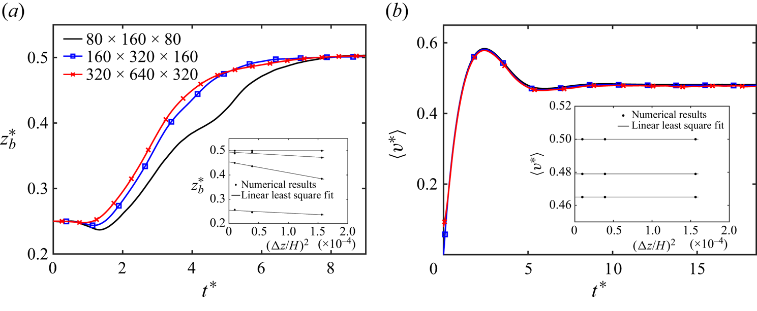
Figure 10. (a) Evolution of particle displacement in the wall-normal ( $z$) direction and (b) the average streamwise component of flow velocity in the channel are shown at different grid resolutions. Linear least-squares fits at different time intervals are shown in the respective insets. (
 $Re=18.9, El=0.05, Ca=0.01, \alpha =0$).


 Open access