Nomenclature
- FTC
-
fault tolerant control
- ACS
-
attitude control system
- FDD
-
fault detection and diagnosis
- EKF
-
extended Kalman filter
- CAM
-
control allocation matrix
- MMFD
-
multiple model fault diagnosis
- i-ACEKF
-
the i-th actuator corresponds to the EKF
- ACEKF
-
actuator corresponds to the extended Kalman filter
- SCKF
-
the sensor corresponds to the Kalman filter
- j-SCKF
-
the j-th sensor corresponds to the Kalman filter
- WSSR
-
the weighted sum of squares of residual
- BCL
-
basic control law
- CDL
-
control distribution law
- ABSA-1
-
actuator booster swing angle 1
1.0 Introduction
With the booming space activities in today’s world and the increasing demand for international commercial launches, the development of a new generation of launch vehicles is the key to future space development planning [Reference Li and Li1]. The attitude control system (ACS), as the core system of the launch vehicle, has a complex structure and is prone to failure. According to statistics, ACS failures account for more than 60% of all system failures [Reference Wang2]. Fault diagnosis and FTC technology can make full use of the fault information through parameter adjustment, control reconfiguration and other measures so that the system can maintain a certain control performance under the fault state to ensure the successful completion of the mission, which has been widely used in the design of aerospace flight control systems.
The existing fault detection and diagnosis (FDD) techniques are mainly classified into three types of methods, model-based, data-based and knowledge-based. Considering the easy availability of ACS mathematical models and the scarcity of flight history data, model-based fault diagnosis methods occupy the majority of the research, particularly, the methods for diagnosing by establishing observers have attracted wide attention [Reference Rank3]. For example, in [Reference Venkateswaran, Siva and Goel4], an actuator fault diagnosis method was studied for the design of corresponding observers for satellite attitude control systems. In [Reference Caliskan and Hajiyev5], the fault-tolerant control of a flight control system under sensor/actuator failure is accomplished using the Kalman filter technique and control reconstruction approach. A sliding film controller is utilised to accomplish high-precision tracking of the attitude with finite-time convergence in [Reference Tang, Lin, Zheng, Fan and Ye6], which investigates an adaptive finite-time extended state observer to estimate the brake failure of the attitude system. According to [Reference Bernardi and Adam7], a collection of full-order linear parameter-varying unknown input observers is intended to identify, distinguish, and estimate sensor parameters for nonlinear system failure detection.
Fault tolerant control (FTC) techniques are mainly categorised into passive fault tolerant control and active fault tolerant control, which can ensure the stability of the system while effectively compensating for the fault loss. Most of the existing passive FTC techniques are based on Lyapunov functions and use theoretical methods to construct fault tolerant controllers, such as smooth mode control [Reference Xiao, Hu and Wang8], adaptive control [Reference Hu, Gao, Ren and Liu9] and backward control [Reference Lee and Youdan10]. However, the design and derivation forms of such controllers are too complex, and most of them are only for a single fault mode, which makes it difficult to ensure the stability of control under extreme faults. Due to the limited onboard storage space and computational capability, passive FTC is rarely used in practical engineering.
The main difference between active FTC over passive FTC is that the structure of this sort of controller is not fixed, and the gain or structure may be altered by giving fault information via the FDD module [Reference Jing, Zang, Yang, Cheng, Ma and Cheng11]. For example, an unscented Kalman filter based on a multimodel approach integrated with a PD controller for active FTC was built for a precise estimate of the attitude control system [Reference Zhu, Shen and Danwei12]. To effectively increase the rocket attitude tracking accuracy, an adaptive fault observer is built in [Reference Liang, Hu, Zhou and Wang13], and the sliding model fault-tolerant controller is devised on this premise. In [Reference Gao, Zhou and Qian14], backstepping and adaptive methods are used with fault observation information to develop an active fault-tolerant controller. According to [Reference Cao, Gong, Cheng and Xue15], a spacecraft attitude FTC is implemented using an adaptive learning observer based on a backpropagation controller. It can be seen that this type of control method has strong autonomy, diversified design methods, and means, makes full use of analysis redundancy, and can reasonably ensure the stability of the system in the event of known or unknown faults with the advantages of system hardware and software. Additionally, the use of active FTC approaches in aircraft engineering is mostly successful. Examples of this include the Falcon 9 rocket, which used fault diagnostic and online reprogramming techniques to launch an engine with thrust failure during the maiden ISS flight in 2012 and complete the mission. Additionally, the Chinese CZ-5 new-generation launch vehicle successfully achieved attitude stability control after the booster engine was turned off by using the engine control force dynamic distribution technology [Reference Li and Li1].
In order to better realise the FTC of the system, inspired by the previous studies, this paper proposes a multimodel fault diagnosis (MMFD) and FTC algorithm to accurately track and stabilise the rocket’s attitude angle, taking into account a variety of typical failure modes. The following is the paper’s structure. The launch vehicle minor deviation attitude dynamics model is established in Chapter 2. In Chapter 3, numerous Kalman filters with different topologies are built to model the features of actuator and sensor failure, respectively. The technique and approach for fault identification and isolation are proposed in Chapter 4. The fault diagnostic information is used in Chapter 5 to perform FTC. Chapter 6 conducts simulation research to validate the efficacy of the multiple-model fault diagnosis and FTC algorithm. Chapter 7 is the conclusion.
2.0 Research subject analysis
This paper considers a large Chinese launch vehicle the Long March 5B, which is primarily responsible for launching the core modules and experimental modules of the space station, and is currently the heaviest Chinese rocket with near-Earth orbit capability, with a takeoff weight of about 837.5 tons [Reference Perrett16]. There are eight swing angles at the tail part of the arrow body, among them,
![]() $\delta x j _1 $
,
$\delta x j _1 $
,
![]() $\delta x j _3 $
, and
$\delta x j _3 $
, and
![]() $\delta z t _1 $
,
$\delta z t _1 $
,
![]() $\delta z t _3 $
control the pitch channel,
$\delta z t _3 $
control the pitch channel,
![]() $\delta x j _2 $
,
$\delta x j _2 $
,
![]() $\delta x j _4 $
and
$\delta x j _4 $
and
![]() $\delta z t _2 $
,
$\delta z t _2 $
,
![]() $z t _4 $
control the yaw channel. The eight swing angles control the roll channel of the rocket. The engine layout and swing mode are shown in Fig. 1 below.
$z t _4 $
control the yaw channel. The eight swing angles control the roll channel of the rocket. The engine layout and swing mode are shown in Fig. 1 below.
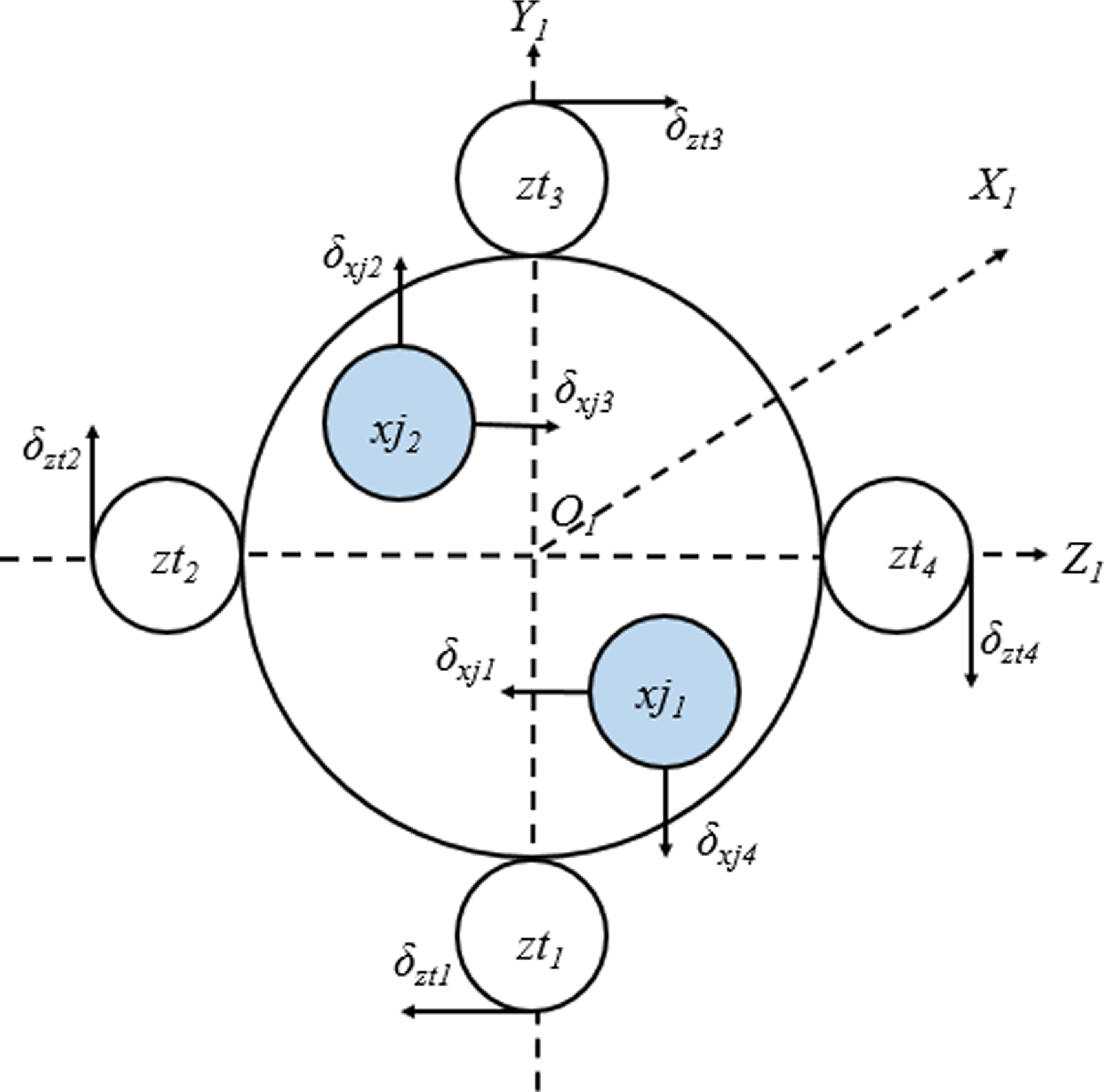
Figure 1. Engine layout of some strap-on launch vehicles from the bottom view [Reference Yang, Xie, Cheng, Song and Cui24].
The rocket channels are decoupled and the small deviation attitude dynamics are modeled as follows.
where
![]() $\Delta \varphi, \psi , \gamma , \Delta \theta, \Delta \alpha, \sigma, \beta $
are the deviations of the rocket’s attitude angle from each Euler angle during flight, respectively,
$\Delta \varphi, \psi , \gamma , \Delta \theta, \Delta \alpha, \sigma, \beta $
are the deviations of the rocket’s attitude angle from each Euler angle during flight, respectively,
![]() $\Delta $
δφzt,
$\Delta $
δφzt,
![]() $\Delta $
δψzt,
$\Delta $
δψzt,
![]() $\Delta $
δγzt are equivalent swing angle commands for booster engines,
$\Delta $
δγzt are equivalent swing angle commands for booster engines,
![]() $\Delta $
δφxj,
$\Delta $
δφxj,
![]() $\Delta $
δψxj,
$\Delta $
δψxj,
![]() $\Delta $
δγxj are the equivalent swing angle command for the core stage engine. The detailed derivation procedure and symbolic meaning are presented in [Reference Zhi17].
$\Delta $
δγxj are the equivalent swing angle command for the core stage engine. The detailed derivation procedure and symbolic meaning are presented in [Reference Zhi17].
If we set,
the system state equation may be written as
where x, y, and u are state variables, sensor measured values, and control commands, respectively, A, B, C, and M are the state matrix; w, v are system noise and measurement noise, respectively, they are uncorrelated Gaussian white noise, i.e.
where
![]() ${\tau _{kj}} = \left\{ {\begin{array}{*{20}{c}}{1,k = j}\\{0,k \ne j}\end{array}} \right.$
${\tau _{kj}} = \left\{ {\begin{array}{*{20}{c}}{1,k = j}\\{0,k \ne j}\end{array}} \right.$
The system is sampled at the moment t(k) = kT. By discretising Equation (7), we could obtain
where F(k) = AT + I, D(k) = BT, H(k) = C.
Assuming the system is completely scalable, the Kalman filtering algorithm flow is as follows [Reference Yaakov Bar-Shalom, Rong and Kirubarajan18].
-
1) Prediction equation. The result of the previous step is used as the initial value for this calculation. As shown in Equations (12) and (13).
(12) \begin{align}\hat x({\left. k \right|k - 1}) = F( {k - 1} )\hat x( {\left. {k - 1} \right|k - 1} ) + D( {k - 1} )u( {k - 1} ) + M( {k - 1} )\end{align}
(13)
 \begin{align}P({\left. k \right|k - 1}) = F( {k - 1} )P( {\left. {k - 1} \right|k - 1} )F{( {k - 1} )^T} + E( {k - 1} )Q( {k - 1} )E{( {k - 1} )^T}\end{align}
-
2) The Kalman gain matrix is calculated.
(14) \begin{align}K(k) = P({\left. k \right|k - 1}){H^T}{\left[ {HP({\left. k \right|k - 1}){H^T} + R(k)} \right]^{ - 1}}\end{align}
-
3) Updates the equation.
(15) \begin{align}P( {\left. k \right|k} ) = \left[ {I - K(k)H} \right]P({\left. k \right|k - 1})\end{align}
(16)
 \begin{align}\hat x( {\left. k \right|k} ) = \hat x({\left. k \right|k - 1}) + K(k)\left[ {y(k) - H\hat x({\left. k \right|k - 1})} \right]\end{align}
Where the initial conditions are
(17) \begin{align}\hat x( 0 ) = {x_{0\;}},\,\,P( {\left. 0 \right|0} ) = {P_0}\end{align}
The Kalman filter residual for this system is
(18) \begin{align}\Delta r(k) = y(k) - H(k)\hat x({\left. k \right|k - 1})\end{align}
When a system fault occurs, the residuals change rapidly, and statistical features can be analysed to detect system faults. However, the above generalised Kalman filter can only identify faults and cannot isolate the type of fault or diagnose the size of the problem. For this reason, this paper proposes an MMFD algorithm to realise the FDD of the system and at the same time provide effective information for the FTC of the system.
3.0 The design of the Kalman filter set
The Kalman filter of the corresponding structure is built using the features of actuator and sensor failures. First, the methods for detecting actuator faults and estimating parameter values are presented.
3.1 Actuator malfunction
Typical failures of launch vehicle actuators include engine swing angle jamming, actuator damage, and loose float swing [Reference Li, Xu, Zhou and Ma19]. The real swing angle of the i-th actuator failure can be represented as
where
![]() ${u_i}^{\prime}\;$
is the true swing angle value after the failure of the i-th actuator,
${u_i}^{\prime}\;$
is the true swing angle value after the failure of the i-th actuator,
![]() ${e_i}$
is the non-zero matrix (
${e_i}$
is the non-zero matrix (
![]() ${e_i}=1,{e_j}=0, i \neq j $
),
${e_i}=1,{e_j}=0, i \neq j $
),
![]() ${\tilde \delta _i}$
is the magnitude of the failure of the i-th actuator. The system equation of state after the i-th actuator failure is as follows.
${\tilde \delta _i}$
is the magnitude of the failure of the i-th actuator. The system equation of state after the i-th actuator failure is as follows.
 \begin{align}\left\{ {\begin{array}{*{20}{c}}{x({k + 1}) = F(k)x(k) + {D^{remain}}(k)u(k) + {D^i}(k){{\tilde \delta }_i}(k)}\\{ + M(k) + w(k)\;\;\;\;\;\;\;\;\;\;\;\;\;\;\;\;\;\;\;\;\;\;\;\;\;\;\;\;\;\;\;\;\;\;\;\;\;\;\;\;\;\;\;\;\;\;\;\;\;\;\;\;\;\;\;\;\;\;\;\;\;\;\;\;\;\;\;}\\{y(k) = Hx(k) + v(k)\;\;\;\;\;\;\;\;\;\;\;\;\;\;\;\;\;\;\;\;\;\;\;\;\;\;\;\;\;\;\;\;\;\;\;\;\;\;\;\;\;\;\;\;\;\;\;\;\;\;\;\;\;\;\;\;}\end{array}} \right.\end{align}
where
![]() ${D^i}(k)$
is the i-th column of the matrix,
${D^i}(k)$
is the i-th column of the matrix,
![]() ${D^{remain}}(k)$
is the matrix after the i-th column of the matrix is sets to zero.
${D^{remain}}(k)$
is the matrix after the i-th column of the matrix is sets to zero.
To obtain information about the actuator failure parameters, the state variables of Equation (4) are extended as follows,
Then the equation of state can be expressed as
 \begin{align}\left\{ {\begin{array}{*{20}{l}}{\bar x({k + 1}) = G(k)\left[ {\begin{array}{*{20}{c}}{x(k)}\\{{{\tilde \delta }_i}(k)}\end{array}} \right] + L(k)u(k) + \left[ {\begin{array}{*{20}{c}}1\\0\end{array}} \right]M(k) + w(k)}\\{y(k) = \left[ {\begin{array}{*{20}{cccc}}H && 0\end{array}} \right]\left[ {\begin{array}{*{20}{c}}{x(k)}\\{{{\tilde \delta }_i}(k)}\end{array}} \right] + v(k)}\end{array}} \right.\end{align}
where
![]() $G(k) = \left[ {\begin{array}{*{20}{cccc}}{F(k)} && {{D^i}(k)}\\ 0 && 1\end{array}} \right]$
,
$G(k) = \left[ {\begin{array}{*{20}{cccc}}{F(k)} && {{D^i}(k)}\\ 0 && 1\end{array}} \right]$
,
![]() $L(k) = \left[ {\begin{array}{*{20}{c}}{{D^{remain}}(k)}\\0\end{array}} \right]$
.
$L(k) = \left[ {\begin{array}{*{20}{c}}{{D^{remain}}(k)}\\0\end{array}} \right]$
.
From the system in Equation (22), the Kalman filter equation for the i-th actuator fault is obtained [Reference Theilliol, Sauter and Ponsart20].
At time k + 1, the i-th actuator corresponds to the EKF (i-ACEKF), which can be represented as
This research focuses solely on the failure of a single actuator. When the i-th actuator does not fail, the corresponding residual value follows a multivariate distribution with a zero mean; when the i-th actuator fails, the corresponding residual value
![]() $\Delta {r_i}(k)$
abruptly changes, allowing the associated failure to be discovered and isolated.
$\Delta {r_i}(k)$
abruptly changes, allowing the associated failure to be discovered and isolated.
3.2 Sensor malfunction
The platform and rate gyroscope are used to measure the attitude angle and angular rate of the carrier rocket, respectively [Reference Wang, Zhang, Hong and Li21]. According to the different sensor installation positions, the measurement signal can be expressed as
where
![]() ${w_p}^{\prime}\left( {{x_T}} \right)$
is the slope of the p-th oscillation at the attitude angle measurement device installation,
${w_p}^{\prime}\left( {{x_T}} \right)$
is the slope of the p-th oscillation at the attitude angle measurement device installation,
![]() ${w_p}^{\prime}\left( {{x_s}} \right)$
is the slope of the p-th oscillation at the velocity gyro mounting.
${w_p}^{\prime}\left( {{x_s}} \right)$
is the slope of the p-th oscillation at the velocity gyro mounting.
The main manifestations of the launch vehicle sensor failure are jamming, bias, increased drift, and increased noise [Reference Li, Xu, Zhou and Ma19]. Since the structure of the sensor corresponds to the Kalman filter (SCKF) is relatively simple, and the coupling between filter equations is weak. When only the sensor fails, the system (11) can be rewritten as
 \begin{align}\left\{ {\begin{array}{*{20}{l}}{x({k + 1}) = F(k)x(k) + D(k)u(k) + M(k) + w(k)}\\{\left[ {\begin{array}{*{20}{c}}{{y_j}(k)}\\{{y_{remain}}(k)}\end{array}} \right] = \left[ {\begin{array}{*{20}{c}}{{H_j}}\\{{H_{remain}}}\end{array}} \right]x(k) + v(k) + \left[ {\begin{array}{*{20}{c}}{{f_j}(k)}\\{{f_{remain}}(k)}\end{array}} \right]}\end{array}} \right.\end{align}
where
![]() ${y_j}(k)$
,
${y_j}(k)$
,
![]() ${f_j}(k)$
are the j-th row of the system output vector and the sensor fault vector, respectively,
${f_j}(k)$
are the j-th row of the system output vector and the sensor fault vector, respectively,
![]() ${y_{remain}}(k)$
,
${y_{remain}}(k)$
,
![]() ${f_{remain}}(k)$
are the remaining rows of the system output vector and sensor fault vector, respectively.
${f_{remain}}(k)$
are the remaining rows of the system output vector and sensor fault vector, respectively.
![]() ${H_j}$
is the j-th row of the H matrix in Equation (11),
${H_j}$
is the j-th row of the H matrix in Equation (11),
![]() ${H_{remain}}$
is the remaining row of the H-matrix in the system.
${H_{remain}}$
is the remaining row of the H-matrix in the system.
According to the system in Equation (32), the Kalman filter equation when the j-th sensor fails can be obtained.
The j-th sensor corresponds to the Kalman filter (j-SCKF) at moment k + 1 can be expressed as
From Equation (38), if the state estimate is unbiased at the initial moment when the j-th sensor is without failure i.e., f
i
= 0, the state estimated by the j-SCKF is unbiased for system (32) and the residuals conform to the multivariate distribution with zero mean; when a fault occurs in the j-th sensor, i.e., f
i
![]() $ \ne $
0, the residual has changed, so that the failure can be detected and isolated and has no effect on the residuals of the remaining SCKF.
$ \ne $
0, the residual has changed, so that the failure can be detected and isolated and has no effect on the residuals of the remaining SCKF.
4.0 The multimodel fault diagnosis algorithm isolation strategy
4.1 The flow of the multimodel fault diagnosis algorithm
The MMFD algorithm developed in this research is applicable to actuator or sensor failures in any state of the carrier rocket. In order to reduce the influence of noise on the diagnosis results, the sum of the weighted squares algorithm is used to process the residual signal, and the formula is as follows.
where N is the length of the data window. When N is increased, the robustness of the system detection increases, and the likelihood of false alarms decreases, but the system’s computation amount increases.
The idea of a classical special observer is applied to the failure of the launch vehicle actuator, and the principle of fault detection and isolation based on the MMFD algorithm is shown in Fig. 2, where
![]() $\Delta r_i$
is the residual, which is the difference between the predicted output value of the Kalman filter and the measured value.
$\Delta r_i$
is the residual, which is the difference between the predicted output value of the Kalman filter and the measured value.
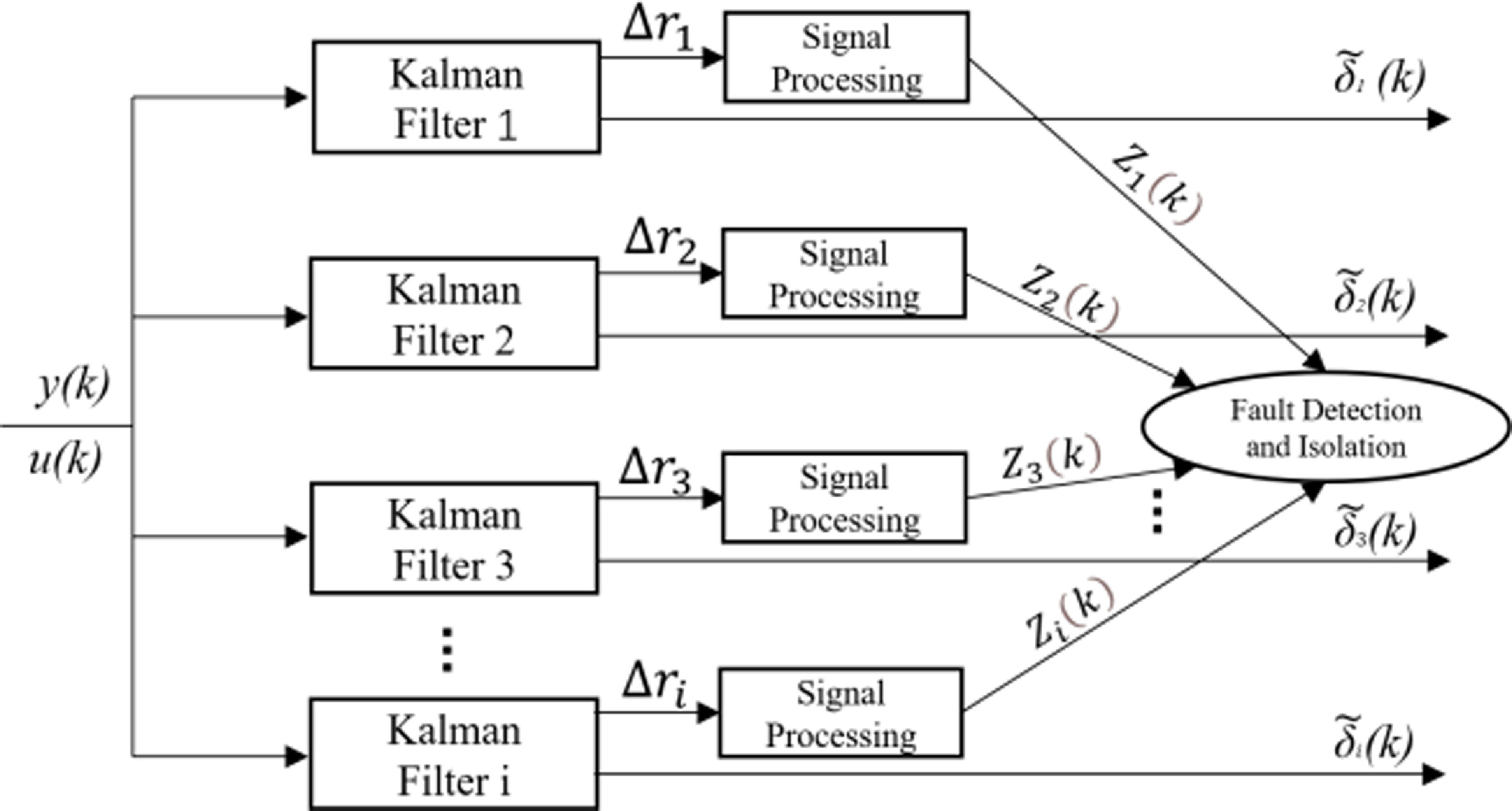
Figure 2. Flowchart of launch vehicle actuator based on MMFD algorithm.
The fault detection and isolation process based on the MMFD algorithm is also obtained for the launch vehicle sensor, as illustrated in Fig. 3. And the signal processing modules in Figs. 2 and 3 correspond to the noise reduction processing shown in formula (39).
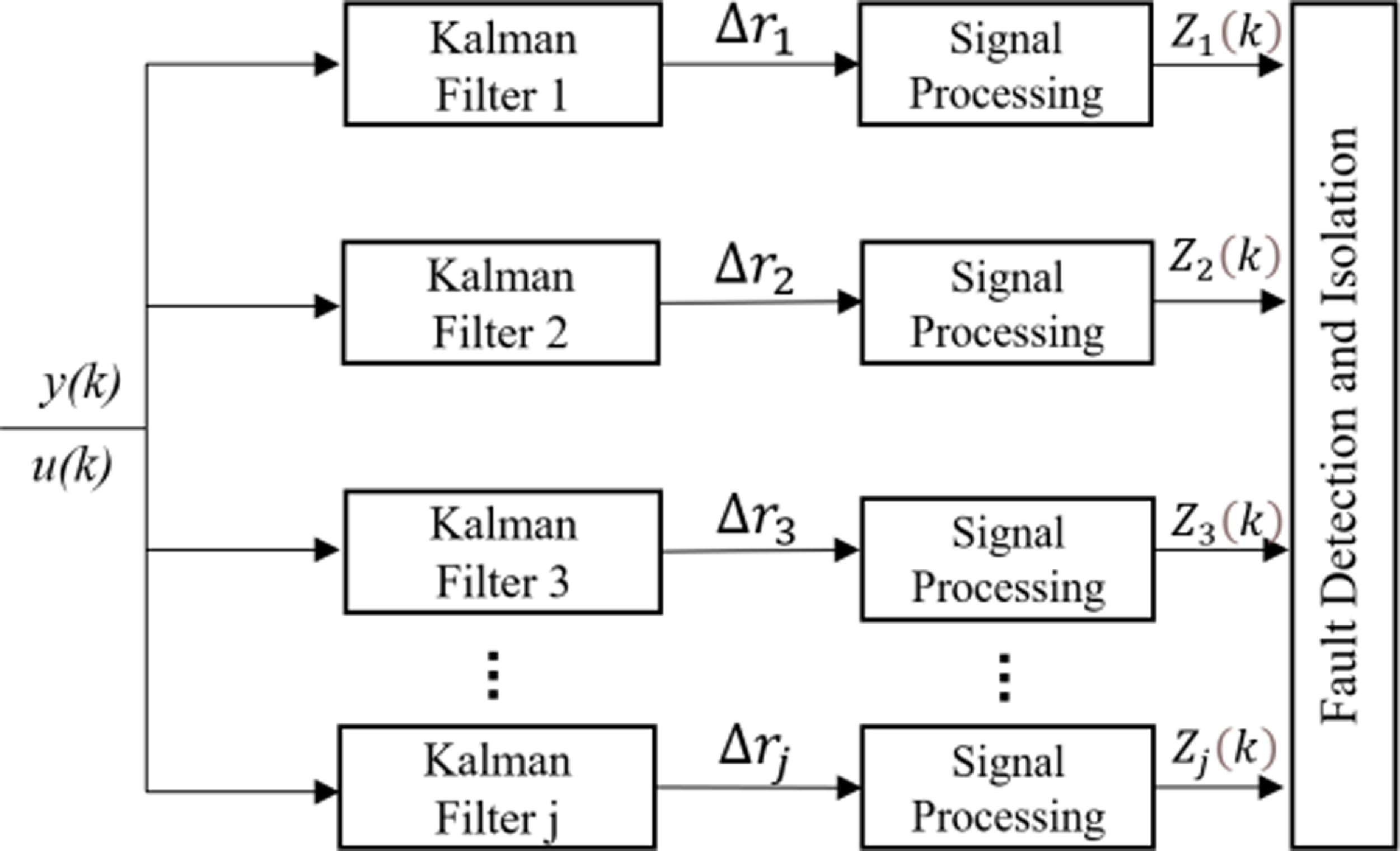
Figure 3. Flowchart of launch vehicle sensor based on MMFD algorithm.
In order to improve detection accuracy and reduce the rate of false alarm and false alarms, a twofold threshold is used for fault detection. After determining the detection threshold DT and absolute threshold, the dual threshold detection method is as follows.
-
1) When the weighted sum of squares of residuals (WSSR)
 ${Z_\tau }(k)$
exceeds the detection threshold for three consecutive moments, it is regarded to have a failure, i.e.,
 ${Z_\tau }(k) \gt $
DT, where k = t, t + 1, t + 2.
 -
2) When the WSSR
 ${Z_\tau }(k)$
exceeds the absolute threshold at a certain time, it is considered to have a failure, i.e.,
 ${Z_\tau }(k) \gt D{T_{Max}}$
.
4.2 Isolation strategy based on multimodel fault diagnosis algorithm
The above methods can only detect and isolate a single fault. In order for the diagnostic system to be able to detect and isolate both actuator and sensor faults, a corresponding isolation strategy needs to be derived.
Since the weak coupling of the SCKF set, the first localisation of faults is performed using this filter set. We can deduct from Equation (38) that several sets of SCKF residuals exceed the threshold when an actuator fails. Considering the extremely low probability of multiple sensors failing at the same time, the multifault isolation technique based on the MMFD algorithm is as follows.
-
1) When only one set of WSSR of SCKF exceeds the threshold, it indicates that the sensor is defective and can be recognised directly.
-
2) When multiple sets of WSSR of SCKF exceed the threshold, it indicates that the actuator is faulty. Then, the actuator corresponding to the EKF (ACEKF) group is utilised to achieve further isolation and localisation. The multifault isolation strategy of the launch vehicle is shown in Fig. 4.

Figure 4. Multi-fault detection and isolation strategy of launch vehicles.
On the basis of the above method, the fault detection and isolation of actuators and sensors were accomplished. Further, richer actuator fault information was obtained by utilising EKF, laying the foundation for FTC of the launch vehicle.
5.0 Fault tolerant control under launch vehicle failure
The ACS is broken into two parts: the basic control law (BCL) and the control distribution law (CDL). Among them, the BCL generally includes the PD control and correction network, whose primary duty is to calculate the rocket attitude angle information measured on the arrow during flight through the basic control law to obtain the virtual control commands for the three channels of rocket pitch, yaw and roll (
![]() $\delta _\varphi ^s\;,\;\delta _\psi ^s\;,\;\delta _\gamma ^s$
); The commands of the BCL are then assigned to the core and boost channels according to a predetermined distribution ratio to obtain the respective equivalent swing angle commands (
$\delta _\varphi ^s\;,\;\delta _\psi ^s\;,\;\delta _\gamma ^s$
); The commands of the BCL are then assigned to the core and boost channels according to a predetermined distribution ratio to obtain the respective equivalent swing angle commands (
![]() ${\rm{\;}}\delta _{\varphi xj}^s\;,\;\delta _{\psi xj}^s\;,\;\delta _{\gamma xj}^s$
and
${\rm{\;}}\delta _{\varphi xj}^s\;,\;\delta _{\psi xj}^s\;,\;\delta _{\gamma xj}^s$
and
![]() $\delta _{\varphi zt}^s\;,\;\delta _{\psi zt}^s\;,\;\delta _{\gamma zt}^s$
). The CDL’s purpose is to deliver comparable swing angle orders to the servo mechanisms on the core stage and boost motors, causing each swing motor to swing to create control torque and, ultimately, adjust the rocket’s flying attitude. Figure 5 illustrates the specific flow.
$\delta _{\varphi zt}^s\;,\;\delta _{\psi zt}^s\;,\;\delta _{\gamma zt}^s$
). The CDL’s purpose is to deliver comparable swing angle orders to the servo mechanisms on the core stage and boost motors, causing each swing motor to swing to create control torque and, ultimately, adjust the rocket’s flying attitude. Figure 5 illustrates the specific flow.
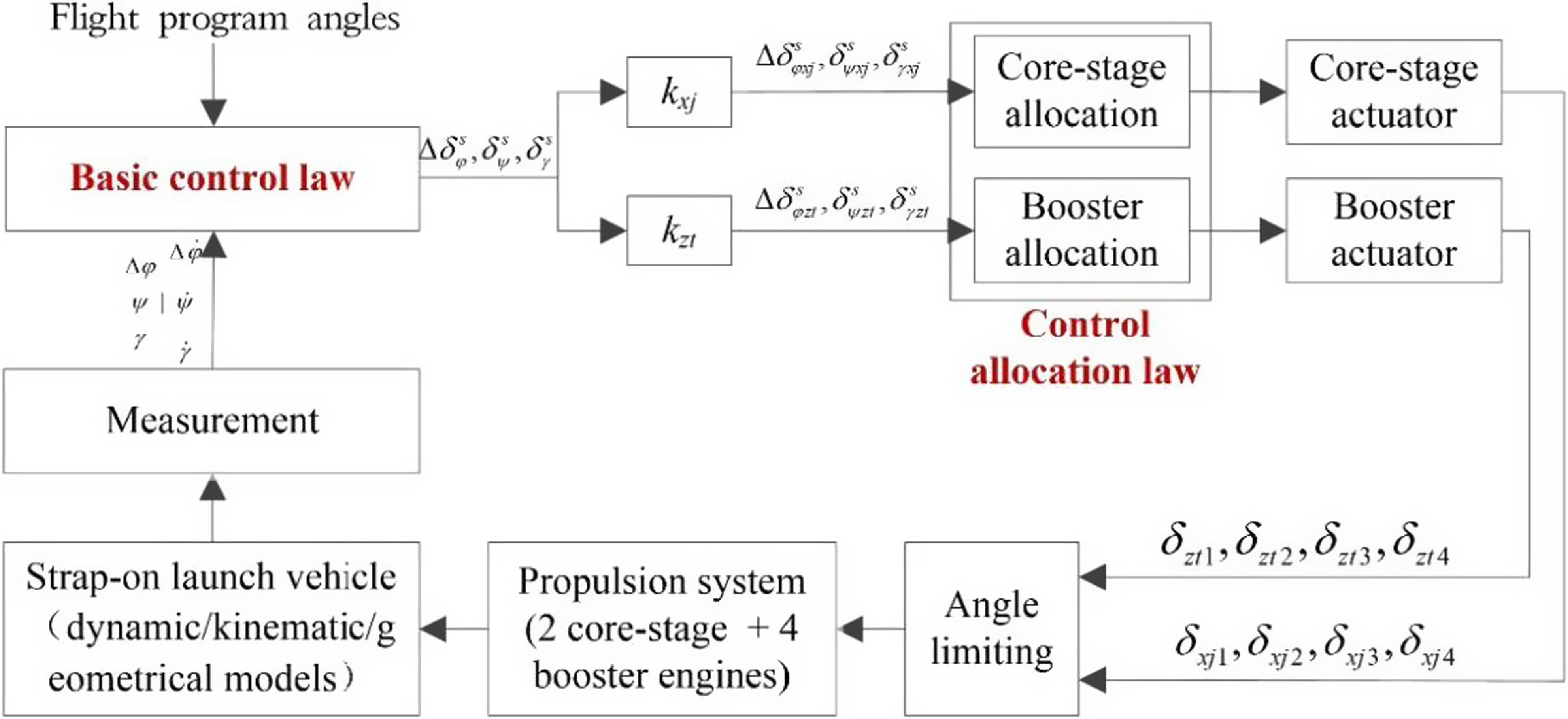
Figure 5. Structure of launch vehicle attitude control system [Reference Yang, Xie, Cheng, Song and Cui24].
5.1 Fault tolerant control under actuator failure
The CDL redistributes the engine swing angle so that the redistributed control torque is equal to the desired generated control torque to achieve FTC under the rocket fault, with the following mathematical expression (the detailed derivation process is shown in Appendix A).
 \begin{align}\left[ {\begin{array}{*{20}{l}}{b_{3x}^\varphi \Delta \delta _{\varphi xj}^s + b_{3z}^\varphi \Delta \delta _{\varphi zt}^s}\\{b_{3x}^\psi \delta _{\psi xj}^s + b_{3z}^\psi \delta _{\psi zt}^s}\\{{d_{3x}}\delta _{\gamma xj}^s + {d_{3z}}\delta _{\gamma zt}^s}\end{array}} \right] = \left[ \begin{array}{cccccccc}0 & - b_{3xj2}^\varphi & 0 & b_{3xj1}^\varphi & 0 & - b_{3zt2}^\varphi & 0 & b_{3zt4}^\varphi \\-b_{3xj1}^\varphi & 0 & b_{3xj2}^\varphi & 0 & -b_{3zt1}^\varphi & 0 & b_{3zt3}^\varphi & 0 \\{d_{3x1}} & {d_{3x2}} & {d_{3x3}} & {d_{3x4}} & {d_{3z1}} & {d_{3z2}} & {d_{3z3}} & {d_{3z4}}\end{array} \right] \times \left[ {\begin{array}{*{20}{c}}{{\delta _x}}\\{{\delta _z}}\end{array}} \right]\end{align}
where
![]() $b_{3x}^\varphi $
,
$b_{3x}^\varphi $
,
![]() $b_{3z}^\varphi $
,
$b_{3z}^\varphi $
,
![]() $b_{3xj1}^\varphi $
,
$b_{3xj1}^\varphi $
,
![]() $b_{3xj2}^\varphi $
,
$b_{3xj2}^\varphi $
,
![]() $b_{3zt2}^\varphi $
,
$b_{3zt2}^\varphi $
,
![]() $\;b_{3zt4}^\varphi $
,
$\;b_{3zt4}^\varphi $
,
![]() $b_{3x}^\psi $
,
$b_{3x}^\psi $
,
![]() $b_{3z}^\psi $
,
$b_{3z}^\psi $
,
![]() $b_{3xj1}^\psi $
,
$b_{3xj1}^\psi $
,
![]() $b_{3xj2}^\psi $
,
$b_{3xj2}^\psi $
,
![]() $b_{3zt1}^\psi $
,
$b_{3zt1}^\psi $
,
![]() $b_{3zt3}^\psi $
,
$b_{3zt3}^\psi $
,
![]() ${d_{3x}}$
,
${d_{3x}}$
,
![]() ${d_{3z}}$
,
${d_{3z}}$
,
![]() ${d_{3x1 - 4}}$
,
${d_{3x1 - 4}}$
,
![]() ${d_{3z1 - 4}}$
are the coefficients of rigid body motion equations, and the detailed meanings can be seen in reference [Reference Zhi17].
${d_{3z1 - 4}}$
are the coefficients of rigid body motion equations, and the detailed meanings can be seen in reference [Reference Zhi17].
![]() $\Delta \delta _{\varphi xj}^s$
,
$\Delta \delta _{\varphi xj}^s$
,
![]() $\Delta \delta _{\varphi zt}^s$
,
$\Delta \delta _{\varphi zt}^s$
,
![]() $\delta _{\psi xj}^s$
,
$\delta _{\psi xj}^s$
,
![]() $\delta _{\psi zt}^s$
,
$\delta _{\psi zt}^s$
,
![]() $\delta _{\gamma xj}^s$
,
$\delta _{\gamma xj}^s$
,
![]() $\delta _{\gamma zt}^s$
are the equivalent swing angle instruction of core stage and boost,
$\delta _{\gamma zt}^s$
are the equivalent swing angle instruction of core stage and boost,
![]() ${\delta _x} = {\left[ {{\delta _{x1\;\;}}{\delta _{x2\;\;}}{\delta _{x3\;\;}}{\delta _{x4\;}}} \right]^{\rm{T}}}$
,
${\delta _x} = {\left[ {{\delta _{x1\;\;}}{\delta _{x2\;\;}}{\delta _{x3\;\;}}{\delta _{x4\;}}} \right]^{\rm{T}}}$
,
![]() ${\delta _z} = {\left[ {{\delta _{z1\;\;}}{\delta _{z2\;\;}}{\delta _{z3\;\;}}{\delta _{z4\;}}} \right]^{\rm{T}}}$
are the swing angle of the core stage and the boost engine, as shown in Fig. 5.
${\delta _z} = {\left[ {{\delta _{z1\;\;}}{\delta _{z2\;\;}}{\delta _{z3\;\;}}{\delta _{z4\;}}} \right]^{\rm{T}}}$
are the swing angle of the core stage and the boost engine, as shown in Fig. 5.
It can be expressed as
where
![]() $M$
is the desired torque,
$M$
is the desired torque,
![]() $B$
is the CAM.
$B$
is the CAM.
If an actuator fails, the MMFD algorithm isolates the failure features of the i-th actuator, and this failure information is integrated into the ACS.
At moment k, the actual swing angle after the failure of the i-th actuator is shown in Equation (19), then the CAM at this point can be expressed as
where
![]() ${B_i}$
is the column vector of the CAM corresponding to the i-th actuator,
${B_i}$
is the column vector of the CAM corresponding to the i-th actuator,
![]() ${B_{remain}}$
,
${B_{remain}}$
,
![]() ${u_{remain}}$
are the remaining columns of the CAM and the remaining rows of the actuator, respectively.
${u_{remain}}$
are the remaining columns of the CAM and the remaining rows of the actuator, respectively.
When the i-th actuator malfunctions, we may inverse solve for the magnitude of the remaining swing angle after redistribution by the CAM, i.e.
Based on the above method, FTC under actuator failure is achieved, as shown in Fig. 6.
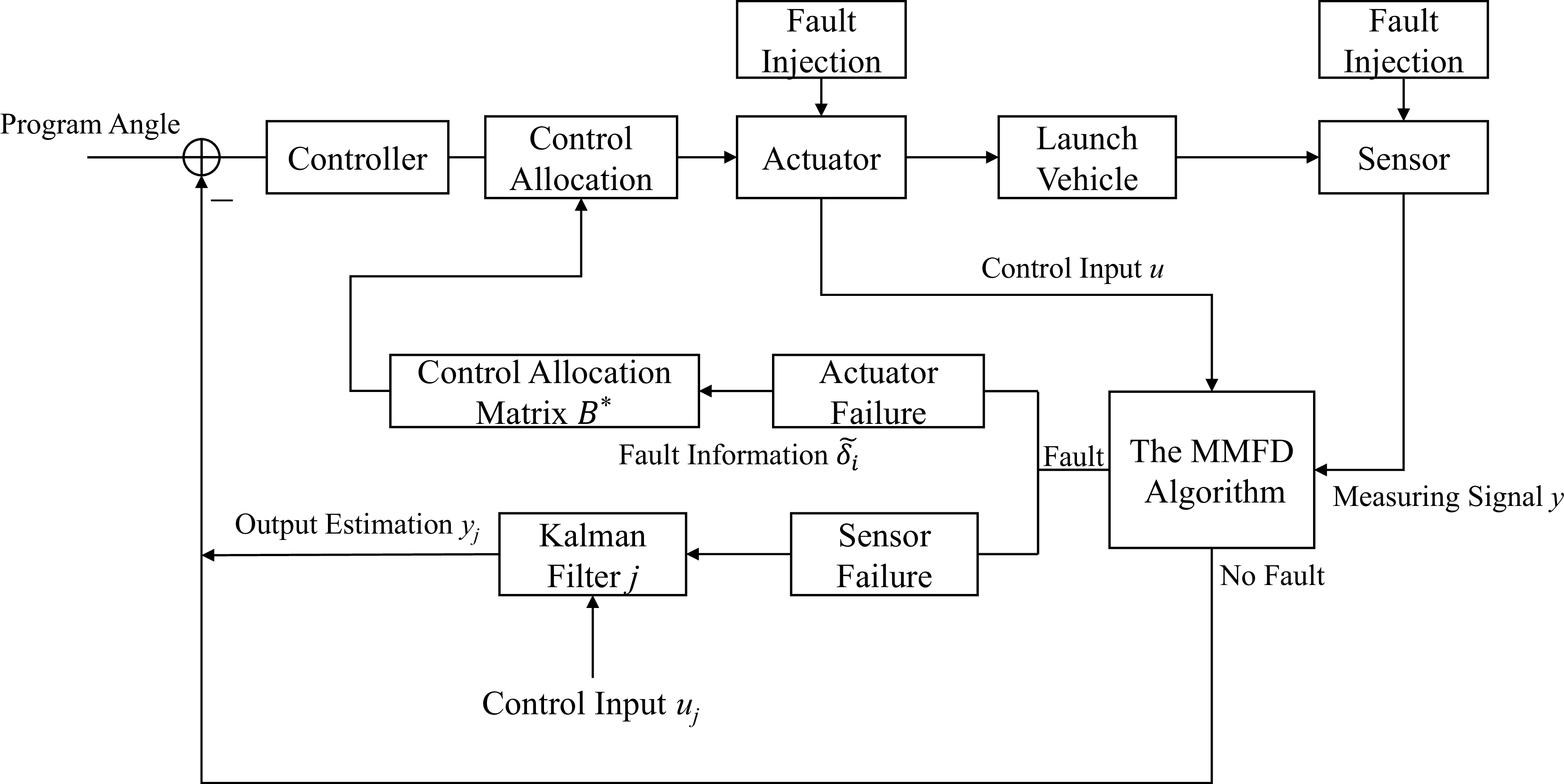
Figure 6. Flow chart of launch vehicle active FTC.
5.2 Fault tolerant control under sensor failure
After using the MMFD algorithm for fault detection of the launch vehicle, if only the faulty sensors are separated, it will lead to a reduction of the monitored measurement parameters, which will not accurately reflect the flight attitude of the rocket and affect the normal operation of the controller.
Considering that the input variables of the jth filter do not contain faulty sensor data at the moment of fault, an accurate estimation of output and state variables can be realised. According to the system in Equation (11), the fault data of the jth sensor is replaced with the corresponding estimated data as shown in Fig. 6.
Fault injection is used to simulate defects during rocket flight, as shown in Fig. 6. When no fault is present, the measured signal y is directly output; when a fault is present, the MMFD method is used to detect and isolate faults of various fault types and to calculate the category and magnitude of the fault. Finally, the necessary reconfiguration steps are performed to mitigate the effects of the problem and restore system performance.
6.0 Numerical validations
To validate the efficiency of the suggested strategy, simulation analysis is performed for several launch vehicle failure scenarios. This study proposes eight Kalman filters for the FDD of actuators, as well as six Kalman filters for the FDD of sensors.
6.1 Faultless state
When the launch vehicle operates correctly, none of the residuals of SCKF and ACEKF weighted square values surpass the threshold value, as seen in Figs. 7 and 8.
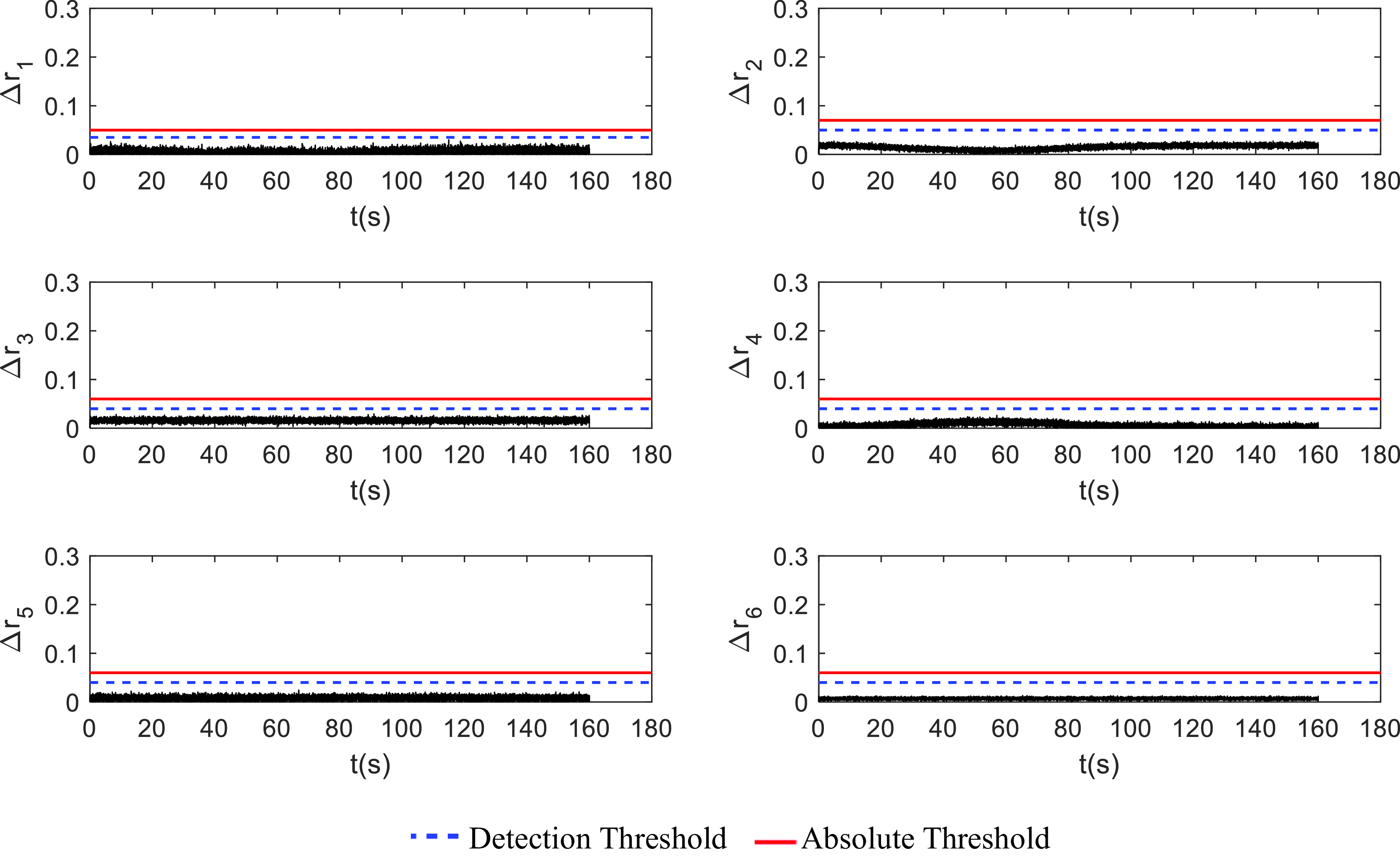
Figure 7. The SCKF group diagram of the faultless state.
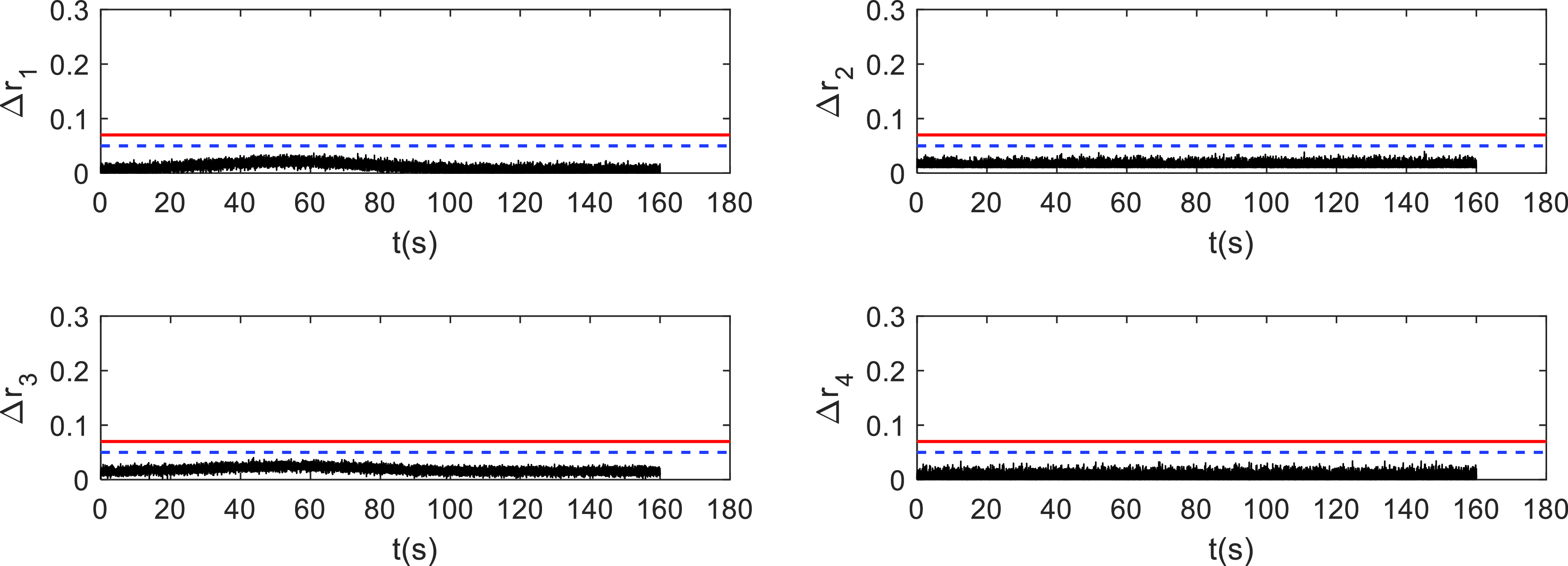
Figure 8. The ACEKF group diagram of the faultless state.
It can be seen that when the system does not fail, there is a certain correspondence between the core stage engine swing angle and the boost engine swing angle, so the simulation curve of
![]() $\Delta {r_5}\sim \Delta {r_8}$
is also similar to
$\Delta {r_5}\sim \Delta {r_8}$
is also similar to
![]() $\Delta {r_1}\sim \Delta {r_4}$
, which is close to the zero-mean multivariate distribution. Due to the influence of wind interference, noise, and other factors, some of the residual values have slight fluctuations, but none of them exceed the set threshold.
$\Delta {r_1}\sim \Delta {r_4}$
, which is close to the zero-mean multivariate distribution. Due to the influence of wind interference, noise, and other factors, some of the residual values have slight fluctuations, but none of them exceed the set threshold.
The estimated value of the pendulum angle of the actuator corresponding to the EKF in the absence of faults is given in Fig. 9, and the actual value in the figure is the normal state value of the system. Due to no change in the rocket control torque, the actuator’s pendulum angle value is close to zero.
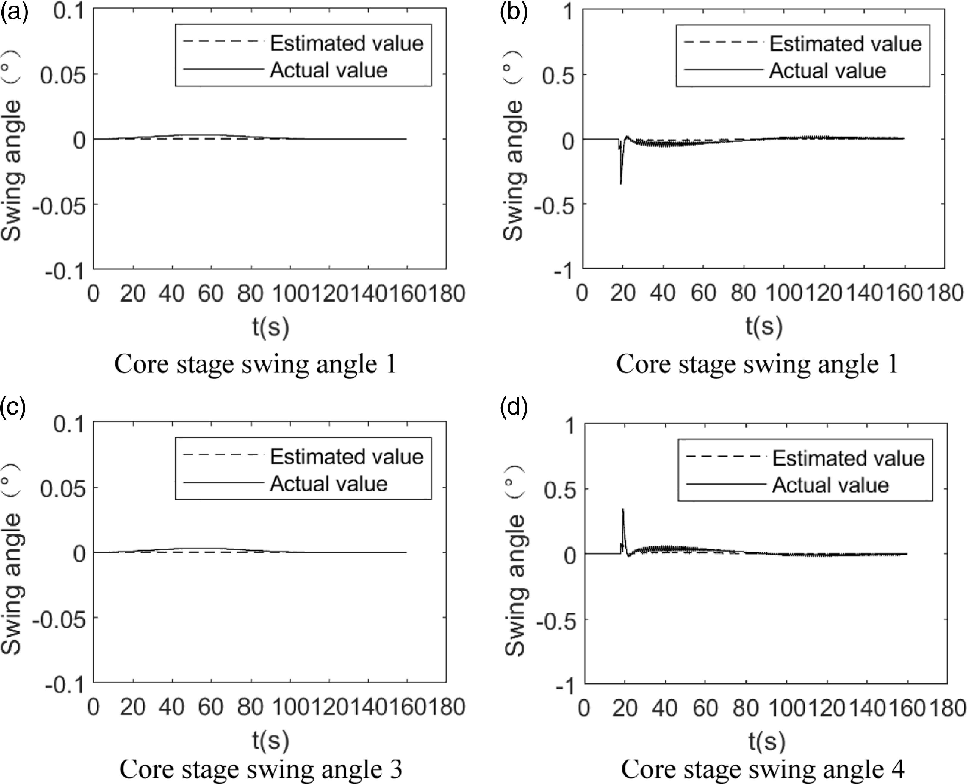
Figure 9. Simulation curve of core stage swing angle.
Combining Figs. 7–9, it is clear that the ACEKF may estimate the angle of each pendulum angle of the actuator. Under fault-free conditions, the MMFD algorithm can perform health detection of the state of the launch vehicle servo mechanism or sensor.
6.2 Sensor failure
Fault 1: A 0.5% constant bias fault occurred in the launch vehicle yaw angle measurement element at the 60s, i.e., a bias fault occurred in the corresponding sensor 1. Figure 8 shows the 1-SCKF residuals simulation curve after the bias fault occurs.
As demonstrated in Fig. 10, when sensor 1 fails, the related residuals surpass the threshold value, but the remainder of the Kalman filter residuals is unaffected, as shown in Fig. 7. As a result, sensor FDD is achieved.
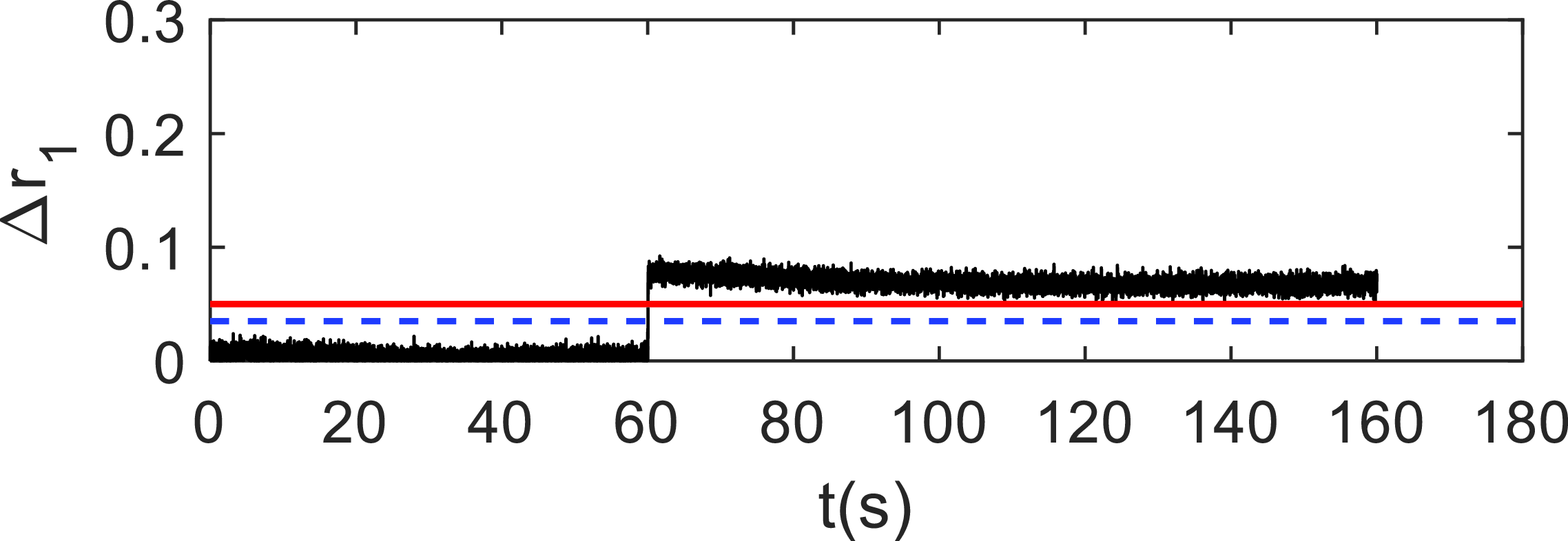
Figure 10. The 1-SCKF residual simulation curve at bias failure.
6.3 Actuator failure
Fault 2: A jamming fault occurred in the launch vehicle actuator booster swing angle 1 (ABSA-1) at the 60s. Figure 11 depicts the SCKF bank residual simulation curve following the jamming fault, while Fig. 12 depicts the 5-ACEKF residual simulation curve.
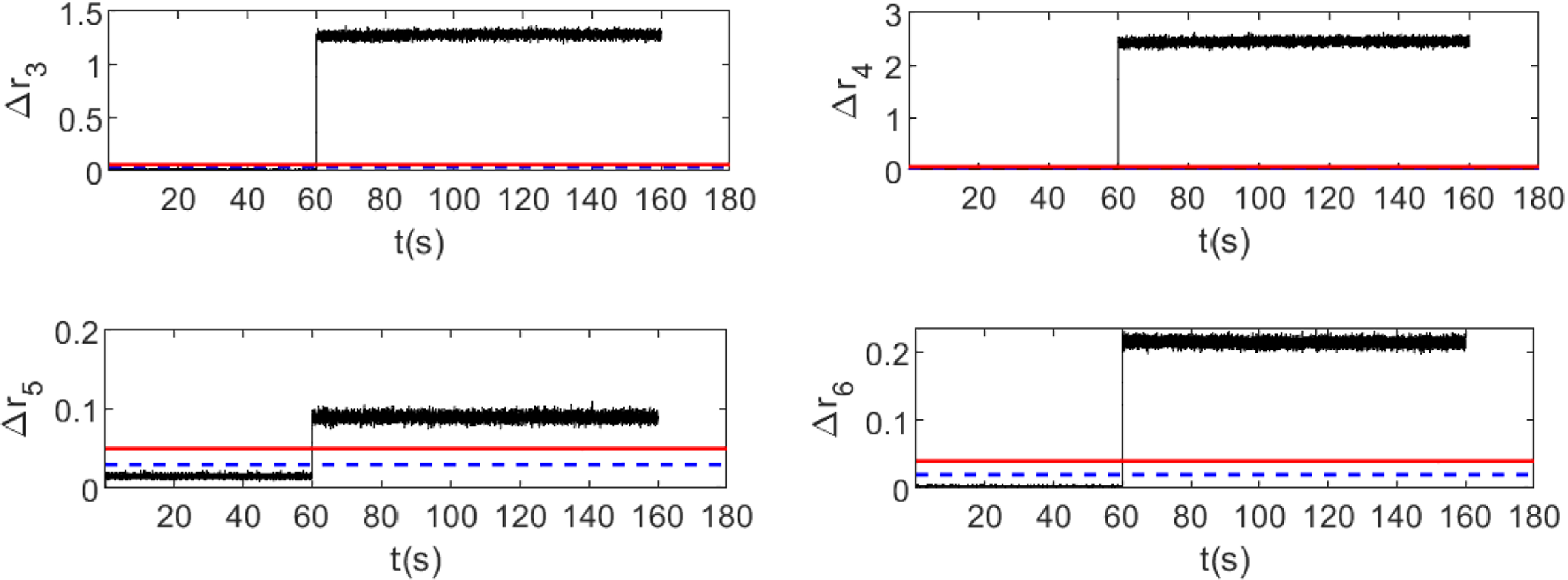
Figure 11. The SCKF group residual simulation curve at jamming fault.
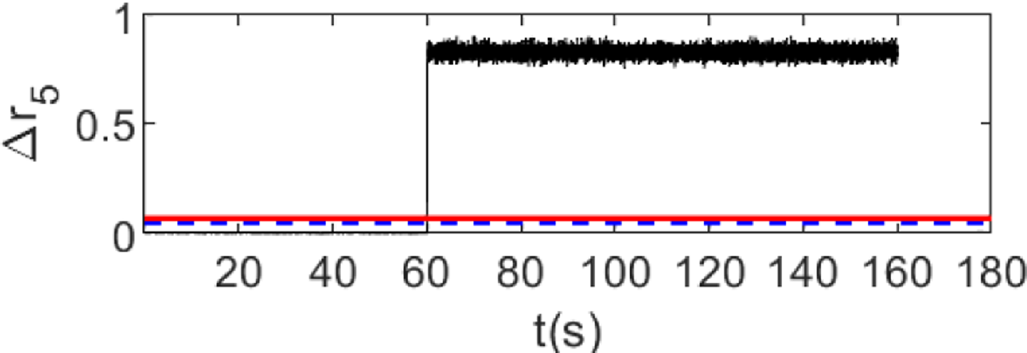
Figure 12. The 5-ACEKF residual simulation curve at jamming fault.
When the actuator fails, the residuals of the SCKF exceed threshold values in four sets, with
![]() $\Delta {r_4}$
(the WSSR of the pitch angle velocity) being the most sensitive to the failure of the ABSA-1, and the remainder of the residual curves still depicted in Fig. 7. According to the fault isolation method based on the MMFD algorithm described in Section 4.2, the actuator has failed at this moment.
$\Delta {r_4}$
(the WSSR of the pitch angle velocity) being the most sensitive to the failure of the ABSA-1, and the remainder of the residual curves still depicted in Fig. 7. According to the fault isolation method based on the MMFD algorithm described in Section 4.2, the actuator has failed at this moment.
From Fig. 12, it can be seen that the 5-ACEKF residual has changed abruptly and exceeded the set threshold value. So, the fault diagnosis result is that the ABSA-1 works normally until the jamming fault occurs at the 60s, thus, the FDD of the actuator can be achieved too.
According to the analysis in Sections 6.1–6.3, the construction of multiple Kalman filters can effectively isolate actuator and sensor faults in any mode, providing accurate information for subsequent FTC decisions.
6.4 Launch vehicle FTC
The preceding subsection implements the launch vehicle’s fault diagnosis using the MMFD algorithm, and the next step is to use the fault diagnostic information for FTC.
For sensor faults, the reconstructed sensor data are imported into the ACS for active FTC. Suppose a bias fault develops in sensor 1 with bias sizes of 0.5%, 0.8% and 1%, respectively. The following Figure 13 depicts the reconstructed results of the measured data following the occurrence of the bias fault.
Figure 13 shows the deviation curves of the pitch angle simulation results from the flight program angle, where the pitch angle simulation curve is corresponding to the measured data of sensor 1. When the sensor data is not reconstructed, the pitch angle deviation increases with increasing bias; after reconstruction, the pitch angle deviation decreases significantly. After a period of time when the failure occurs, the simulation curves after reconstruction with varied bias levels are consistent and near to the normal simulation curves because the measured values are replaced by the estimated values using the relevant Kalman filter. It can be seen that the reconstructed sensor data can meet the requirements of the launch vehicle ACS in terms of accuracy and stability.

Figure 13. Attitude angle deviation curve under sensor bias fault.
For actuator faults, the fault information is brought into Equation (41), and the CDL is used to implement the redistribution of the swing angle for attitude FTC. In this paper, we conduct a control law reconstruction using all functioning core stages and booster engines.
Assume an ABSA-1 jamming failure occurs, with jamming angles of 4°, 6° and 8°, respectively. The following graph depicts the change in attitude angle once the stuck fault occurs.
Figure 14 shows that when a stuck fault occurs in the ABSA-1, the system can respond quickly, and the CAM starts to reconfigure. The fault mainly affects the yaw and roll channels, which appear a slight change at 60s, closely matching the residual variation characteristic in Fig. 11. The b: Stuck angle-8° in Fig. 14(c) represents the roll angle curve of the stuck fault during the reconstruction without control law, when the curve does not converge at this time and the angular deviation is more than 12°. In contrast, the swing angle redistribution can effectively compensate for the torque loss and reduce the attitude angle deviation, whose roll angle error after reconfiguration does not exceed 0.05° (as shown in a: stuck angle-8°).
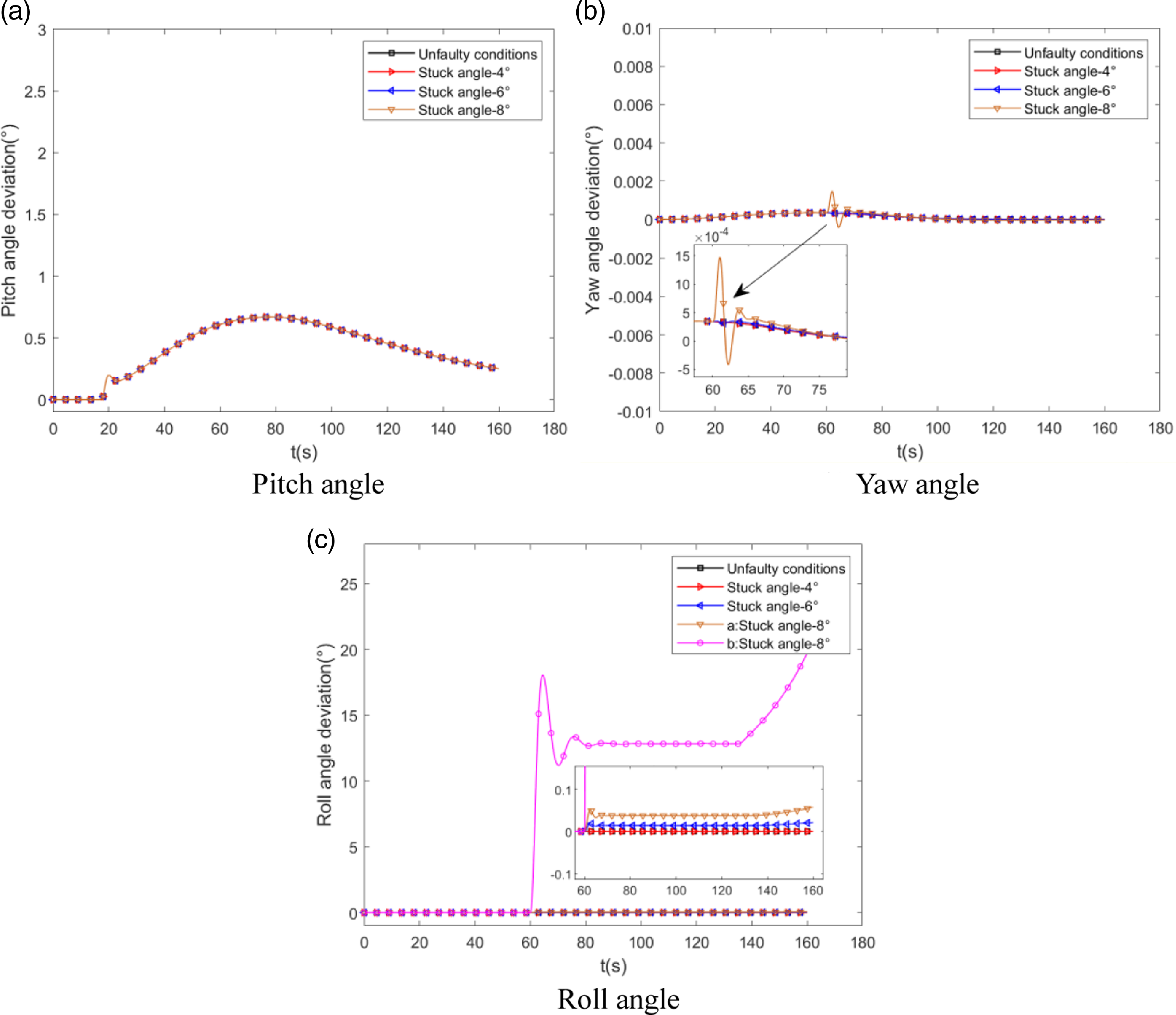
Figure 14. Attitude angle deviation curve under actuator jamming fault.
Figure 15 shows the swing angle reconstruction curve of the actuator when the boost swing angle 1 is stuck at 8°. It can be seen from the figure that after the stuck fault occurs, both the remaining core stage and the boost swing angle will swing substantially, mainly because the system needs to provide more control moments to compensate for the lost control moment and the interference moment caused by the swing angle stuck. Because the core stage and boost swing angle do not exceed the maximum swing angle limit, the system still has a certain safety margin. It can also be seen from Fig. 15(e) that the ACEKF can accurately estimate the fault quantity, and the angle curve of boost swing angle 1 is consistent with the fault injection quantity.
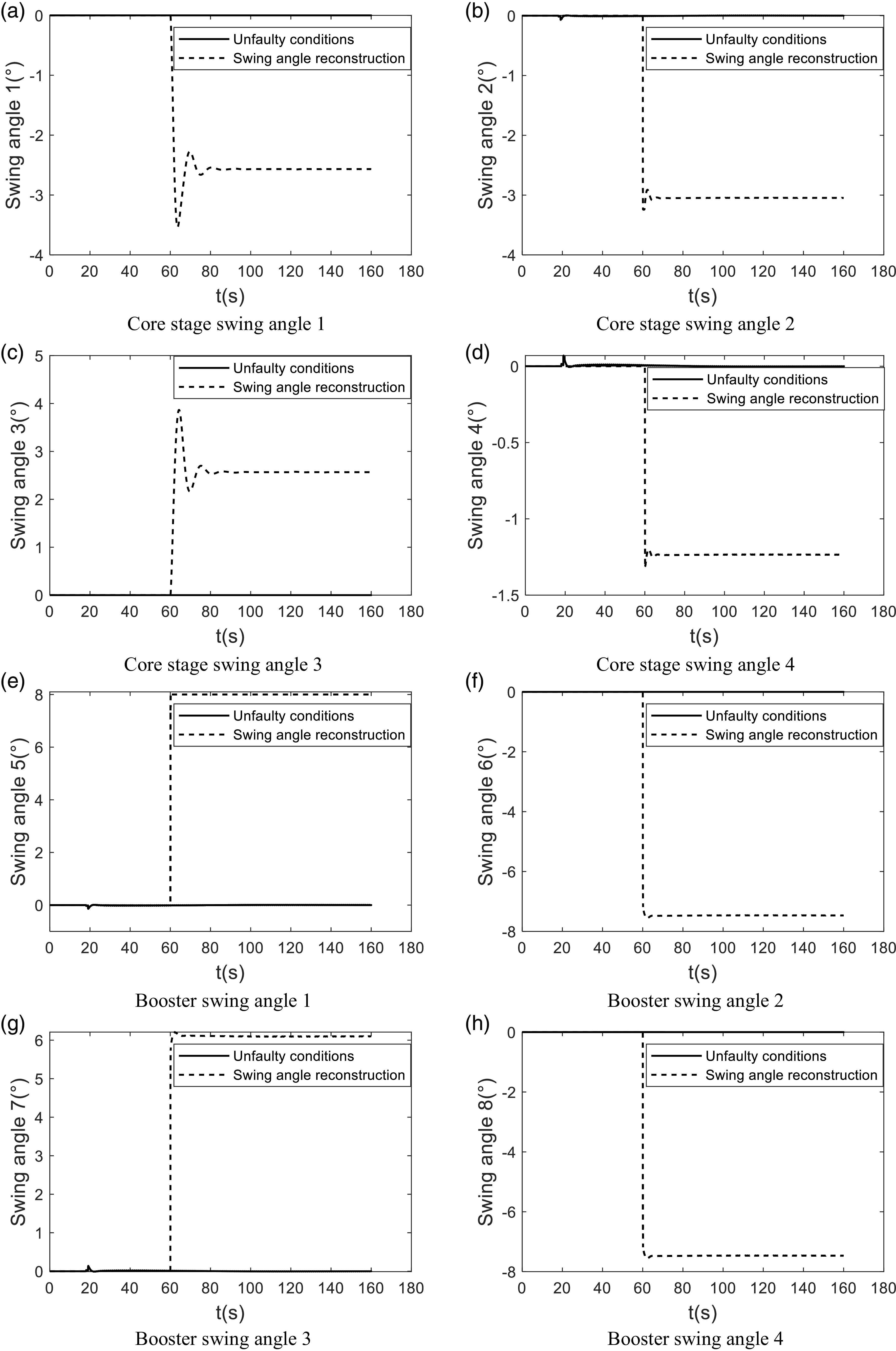
Figure 15. Simulation curve of swing angle after actuator fault reconstruction.
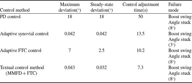
The following table lists the rocket roll Angle attitude control results under different control methods when the actuator is stuck. References (Reference Ma, Shi, Liu, Liang and Wang22,Reference Meng23), whose control object is still a large Chinese launch vehicle (Table 1).
In terms of control results, this method fully utilises the fault information to obtain the optimal control scheme, so the attitude tracking accuracy and control adjustment time are better than other methods. Although adaptive sliding film control can also achieve a better attitude control effect, it only models the actuator faults accordingly. In contrast, this paper considers arbitrary faults of the system sensors and actuators.
Table 1. Comparison of rocket roll angle attitude control results
7.0 Conclusions
In this paper, the problem of fault diagnosis and fault-tolerant control of the launch vehicle attitude control system is investigated, and the effectiveness of the method is verified by fault simulation injection. The main contributions are as follows.
-
(1) A launch vehicle ACS fault diagnosis algorithm is proposed. By analysing the fault characteristics of actuators and sensors, a Kalman filter with different structures is established, which realises the accurate identification of typical faults.
-
(2) The FTC strategy for launch vehicle ACS is designed. Based on the above fault information, the actuator and sensor faults are automatically compensated by reconfiguring the attitude control law. Compared with other control methods, the attitude tracking accuracy and control adjustment time are greatly improved, effectively ensuring the flight stability of the launch vehicle.
Further research may include the establishment of a semi-physical simulation environment to validate the active FTC method proposed in this paper, as well as the consideration of more typical fault models (e.g., valves, pipelines, etc.) to build observation models to improve the robustness of the ACS.
Acknowledgments
The authors would like to thank the peer reviewers of the paper.
Competing interests
The authors declare that they have no known competing financial interests or personal relationships that could have appeared to influence the work reported in this paper.
Appendix A
In Ref. (Reference Yang, Xie, Cheng, Song and Cui24), a small deviation attitude dynamics model of the launch vehicle has been derived. For rocket reconstruction design, considering that the engine swing is very small in the whole flight process, and the motion of the arrow body is a short period process, the effects of the pendulum angle acceleration term caused by the engine swing and the rocket centre of mass motion can be ignored. For the following equation:
After simplification can be obtained,
Then the simplified small-deviation dynamic equation of rocket around the centre of mass is,
 \begin{align*}\Delta\! \mathop \varphi \limits^{ \bullet \bullet } +\, b_1^\varphi \Delta \mathop \varphi \limits^ \bullet +\, b_2^\varphi \Delta \varphi & - b_{3xj2}^\varphi \Delta {\delta _{xj2}} + b_{3xj1}^\varphi \Delta {\delta _{xj4}}\; - b_{3zt2}^\varphi \Delta {\delta _{zt2}} + b_{3zt4}^\varphi \Delta {\delta _{zt4}}\\& = {\bar M_{B{Z_1}}} - b_2^\varphi\! \left( {{\alpha _{wp}} + {\alpha _{wq}}} \right)\end{align*}
 \begin{align*}\mathop \psi \limits^{ \bullet \bullet } +\, b_1^\psi\! \mathop \psi \limits^ \bullet +\, b_2^\psi \psi & - b_{3xj1}^\psi \Delta {\delta _{xj1}} + b_{3xj2}^\psi \Delta {\delta _{xj3}} - b_{3zt1}^\psi \Delta {\delta _{zt1}} + b_{3zt3}^\psi \Delta {\delta _{zt3}}\\& = {\bar M_{B{Y_1}}} - b_2^\psi\! \left( {{\beta _{wp}} + {\beta _{wq}}} \right)\end{align*}
where,
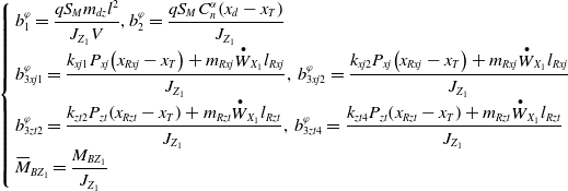 \begin{align*}\left\{ {\begin{array}{*{20}{l}}{b_1^\varphi = \dfrac{{q{S_M}{m_{dz}}{l^2}}}{{{J_{{Z_1}}}V}},b_2^\varphi = \dfrac{{q{S_M}C_n^\alpha\! \left( {{x_d} - {x_T}} \right)}}{{{J_{{Z_1}}}}}}\\[5pt]{b_{3xj1}^\varphi = \dfrac{{{k_{xj1}}{P_{xj}}\!\left( {{x_{Rxj}} - {x_T}} \right) + {m_{Rxj}}{{\mathop W\limits^ \bullet }_{{X_1}}}{l_{Rxj}}}}{{{J_{{Z_1}}}}},{\rm{\;}}b_{3xj2}^\varphi = \dfrac{{{k_{xj2}}{P_{xj}}\!\left( {{x_{Rxj}} - {x_T}} \right) + {m_{Rxj}}{{\mathop W\limits^ \bullet }_{{X_1}}}{l_{Rxj}}}}{{{J_{{Z_1}}}}}}\\[5pt]{b_{3zt2}^\varphi = \dfrac{{{k_{zt2}}{P_{zt}}\!\left( {{x_{Rzt}} - {x_T}} \right) + {m_{Rzt}}{{\mathop W\limits^ \bullet }_{{X_1}}}{l_{Rzt}}}}{{{J_{{Z_1}}}}},{\rm{\;}}b_{3zt4}^\varphi = \dfrac{{{k_{zt4}}{P_{zt}}\!\left( {{x_{Rzt}} - {x_T}} \right) + {m_{Rzt}}{{\mathop W\limits^ \bullet }_{{X_1}}}{l_{Rzt}}}}{{{J_{{Z_1}}}}}}\\[5pt]{{{\bar M}_{B{Z_1}}} = \dfrac{{{M_{B{Z_1}}}}}{{{J_{{Z_1}}}}}}\end{array}} \right.\end{align*}
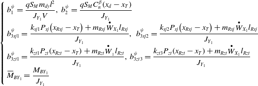 \begin{align*}\left\{ {\begin{array}{*{20}{l}}{b_1^\psi = \dfrac{{q{S_M}{m_{dy}}{l^2}}}{{{J_{{Y_1}}}V}},\;b_2^\psi = \dfrac{{q{S_M}C_n^\beta\! \left( {{x_d} - {x_T}} \right)}}{{{J_{{Y_1}}}}}}\\[5pt]{b_{3xj1}^\psi = \dfrac{{{k_{xj1}}{P_{xj}}\!\left( {{x_{Rxj}} - {x_T}} \right) + {m_{Rxj}}{{\mathop W\limits^ \bullet }_{{X_1}}}{l_{Rxj}}}}{{{J_{{Y_1}}}}},{\rm{\;}}\;b_{3xj2}^\psi = \dfrac{{{k_{xj2}}{P_{xj}}\!\left( {{x_{Rxj}} - {x_T}} \right) + {m_{Rxj}}{{\mathop W\limits^ \bullet }_{{X_1}}}{l_{Rxj}}}}{{{J_{{Y_1}}}}}}\\[5pt]{b_{3zt1}^\psi = \dfrac{{{k_{zt1}}{P_{zt}}\!\left( {{x_{Rzt}} - {x_T}} \right) + {m_{Rzt}}{{\mathop W\limits^ \bullet }_{_1}}{l_{Rzt}}}}{{{J_{{Y_1}}}}},\;b_{3zt3}^\psi = \dfrac{{{k_{zt3}}{P_{zt}}\!\left( {{x_{Rzt}} - {x_T}} \right) + {m_{Rzt}}{{\mathop W\limits^ \bullet }_{{X_1}}}{l_{Rzt}}}}{{{J_{{Y_1}}}}}}\\[5pt]{{{\bar M}_{B{Y_1}}} = \dfrac{{{M_{B{Y_1}}}}}{{{J_{{Y_1}}}}}}\end{array}} \right.\end{align*}
 \begin{align*}\left\{ {\begin{array}{*{20}{l}}{{d_1} = \dfrac{{q{S_M}{m_{dy}}{l^2}}}{{{J_{{X_1}}}V}}}\\[8pt]{{d_{3xj1}} = \dfrac{{\sqrt 2 {k_{xj1}}{P_{xj}}{r_0}}}{{2{J_{{X_1}}}}},{d_{3xj2}} = \dfrac{{\sqrt 2 {k_{xj2}}{P_{xj}}{r_0}}}{{2{J_{{X_1}}}}},{d_{3xj3}} = \dfrac{{\sqrt 2 {k_{xj3}}{P_{xj}}{r_0}}}{{2{J_{{X_1}}}}},{d_{3xj4}} = \dfrac{{\sqrt 2 {k_{xj4}}{P_{xj}}{r_0}}}{{2{J_{{X_1}}}}}}\\[5pt]{{d_{3zt1}} = \dfrac{{{k_{zt1}}{P_{zt}}{r_1}}}{{{J_{{X_1}}}}},{d_{3zt2}} = \dfrac{{{k_{zt2}}{P_{zt}}{r_1}}}{{{J_{{X_1}}}}},{d_{3zt3}} = \dfrac{{{k_{zt3}}{P_{zt}}{r_1}}}{{{J_{{X_1}}}}},{d_{3zt4}} = \dfrac{{{k_{zt4}}{P_{zt}}{r_1}}}{{{J_{{X_1}}}}}}\\[5pt]{{{\bar M}_{B{X_1}}} = \dfrac{{{M_{B{X_1}}}}}{{{J_{{X_1}}}}}}\end{array}} \right.\end{align*}
After the three-channel control instructions
![]() $\delta_\varphi^s, \delta_\psi^s, \delta_\gamma^s$
are calculated according to the basic control law, they are allocated to the core stage three channels and boost three channels according to the pre-designed distribution ratio, that is,
$\delta_\varphi^s, \delta_\psi^s, \delta_\gamma^s$
are calculated according to the basic control law, they are allocated to the core stage three channels and boost three channels according to the pre-designed distribution ratio, that is,
 \begin{align*}\left\{ {\begin{array}{*{20}{l}}{\Delta \delta _{\varphi xj}^s = {k_{xj}}\Delta \delta _\varphi ^s}\\[5pt]{\delta _{\psi xj}^s = {k_{xj}}\delta _\psi ^s}\\[5pt]{\delta _{\gamma xj}^s = {k_{xj}}\delta _\gamma ^s}\end{array}} \right.\;,\,\;\left\{ {\begin{array}{*{20}{l}}{\Delta \delta _{\varphi zt}^s = {k_{zt}}\Delta \delta _\varphi ^s}\\[5pt]{\delta _{\psi zt}^s = {k_{zt}}\delta _\psi ^s}\\[5pt]{\delta _{\gamma zt}^s = {k_{zt}}\delta _\gamma ^s}\end{array}} \right.\end{align*}
The actuator distributes the obtained instructions to each engine according to the pre-designed control distribution law, which can be obtained,
 \begin{align*}\left\{ {\begin{array}{*{20}{l}}{{\delta _{xj1}} = - \delta _{\psi xj}^s + \delta _{\gamma xj}^s}\\{{\delta _{xj2}} = - \Delta \delta _{\varphi xj}^s + \delta _{\gamma xj}^s}\\{{\delta _{xj3}} = \delta _{\psi xj}^s + \delta _{\gamma xj}^s}\\{{\delta _{xj4}} = \Delta \delta _{\varphi xj}^s + \delta _{\gamma xj}^s}\end{array}} \right.\;,\,\left\{ {\begin{array}{*{20}{l}}{{\delta _{zt1}} = - \delta _{\psi zt}^s + \delta _{\gamma zt}^s}\\{{\delta _{zt2}} = - \Delta \delta _{\varphi zt}^s + \delta _{\gamma zt}^s}\\{{\delta _{zt3}} = \delta _{\psi zt}^s + \delta _{\gamma zt}^s}\\{{\delta _{zt4}} = \Delta \delta _{\varphi zt}^s + \delta _{\gamma zt}^s}\end{array}} \right.\end{align*}
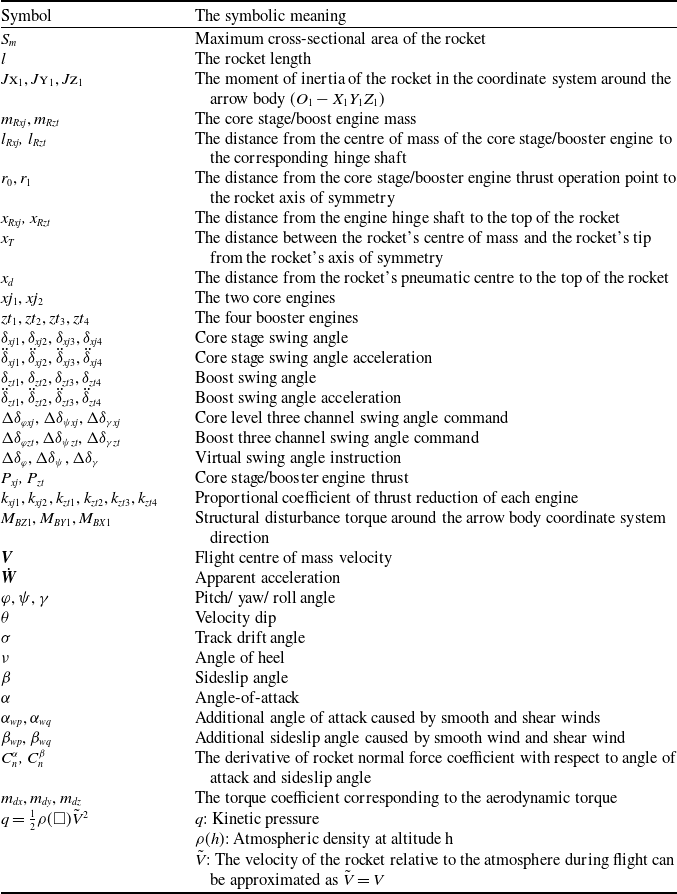
The above is the basic control law of the arrow body when there is no thrust fault. When a fault occurs, the original control distribution law is no longer applicable, and the engine swing angle needs to be redistributed so that the control torque obtained after reallocation is equal to the expected control torque, and formula (40) is obtained, the relevant symbolic meanings of the derivation process are shown in Table 2.
 \begin{align*}\left[ {\begin{array}{*{20}{l}}{b_{3x}^\varphi \Delta \delta _{\varphi xj}^s + b_3^\varphi \Delta \delta _{\varphi zt}^s}\\{b_{3x}^\psi \delta _{\psi xj}^s + b_{3z}^\psi \delta _{\psi zt}^s}\\{{d_{3x}}\delta _{\gamma xj}^s + {d_{3z}}\delta _{\gamma zt}^s}\end{array}} \right] = \left[ {\begin{array}{*{20}{cccccccc}}0 & - b_{3xj2}^\varphi & 0 & b_{3xj1}^\varphi & 0 & - b_{3zt2}^\varphi & 0 & b_{3zt4}^\varphi \\ - b_{3xj1}^\psi & 0 & b_{3xj2}^\psi & 0 & - b_{3zt1}^\psi & 0 & b_{3zt3}^\psi & 0\\{d_{3x1}} & {d_{3x2}} & {d_{3x3}} & {d_{3x4}} & {d_{3z1}} & {d_{3z2}} & {d_{3z3}} & {d_{3z4}}\end{array}} \right] \times \left[ {\begin{array}{*{20}{c}}{{\delta _x}}\\{{\delta _z}}\end{array}} \right]\end{align*}
Table 2. The basic symbol meaning
