I. INTRODUCTION
Surface hardening of metal components is an efficient way of prolonging their lifetime via improvement of resistance to the contact-related phenomena such as wear. However, several widely used hardening processes impose either stringent requirements on the shape of hardened objects, for example in the case of thermal spraying or hard chromium planting, or only a few micrometres thin coating can be deposited by physical or chemical vapor deposition (PVD or CVD), which cannot withstand the severe wear during, e.g. corundum or tungsten carbide powder pressing. The former obstacle connected to irregular complex shapes and sharp edges is commonly tackled by employing thermochemical process of nitriding with peak levels of hardness about 1100 HV (Gopalakrishnan et al., Reference Gopalakrishnan, Ramakrishnan, Shankar and Palaniappa2002). Nevertheless, if the nitriding does not lead to the coveted level of wear-resistance, another diffusion-based process, boriding (sometimes referred to as boronizing) can be applied with hardness of borided steels usually between 1600 and 2000 HV (Davis, Reference Davis2002), which is in the similar range as cermet WC-Co thermal coatings (Kim et al., Reference Kim, Lee and Hwang2005). Both nitriding and boriding have strong links to crystallography as in each process dominantly two phases are created via diffusion of either nitrogen or boron into the treated surface. In the latter case, two crystalline phases of tetragonal Fe2B, which has three polymorphs with space groups I-4/mcm or I-42m, and orthorhombic FeB (Pnma) (Bjurstrom and Arnfelt, Reference Bjurstrom and Arnfelt1929; Wever and Müller, Reference Wever and Müller1930) originate from the interaction of boron atoms, sublimed from the boron-based precursor powder at temperatures from 850 to 950 °C, with iron lattice. Apart from these two phases, the boron readily reacts with an array of alloying elements such as Cr, Mn, Mo, Ni, or W (Zhou et al., Reference Zhou, Xing, Xiao, Feng, Xie and Chen2009). The spatial layout of the boride layer is usually such that FeB is on the surface and the needles in deeper layers are grains of Fe2B (Prümmer and Pfeiffer, Reference Prümmer and Pfeiffer1986). In general, both the FeB and Fe2B layers tend to exhibit higher degree of preferred orientation, most commonly 〈002〉 fibre texture (Kunst and Schaaber, Reference Kunst and Schaaber1967; Prümmer and Pfeiffer, Reference Prümmer and Pfeiffer1986). However, since the thermal expansion coefficient of FeB is around triple of the Fe2B phase, i.e. 23 × 10−6 vs. 7.9 × 10⁻⁶ K−1 (Buijnsters et al., Reference Buijnsters, Shankar, Gopalakrishnan, Van Enckevort, Schermer, Ramakrishnan and Ter Meulen2003), spalling of FeB-cum-oxides and oxy-borides layer frequently occurs when the borided object is cooled to room temperature. Apart from steels, nickel and cobalt-based alloys are also borided for industrial applications (Ueda et al., Reference Ueda, Mizukoshi, Demizu, Sone, Ikenaga and Kawamoto2000; Kalidindi et al., Reference Kalidindi, Vernekar and Jagirdar2009) with origination of Ni2B and Co2B, respectively.
The lifetime of the borided component depends also on the residual stresses (RS) distribution in the borided layer and the adjacent layers of the substrate material and on the overall character of microstructure of the whole area altered by the boriding process. Since the RS superimpose with stresses present during in-service loading, the presence of compressive stresses enhances the fatigue life of components with significant tensile loads (Rodríguez-Castro et al., Reference Rodríguez-Castro, Campos-Silva, Chávez-Gutiérrez, Martínez-Trinidad, Hernández-Sánchez and Torres-Hernández2013). Moreover, the toughness of brittle materials can also be improved by compressive RS (Bermejo et al., Reference Bermejo, Torres, Sanchez-Herencia, Baudín, Anglada and Llanes2006; Campos-Silva et al., Reference Campos-Silva, Ortíz-Domínguez, Hernández-Sánchez, Bravo-Bárcenas, Bravo-Bárcenas, Doñu-Ruíz, Martínez-Trinidad, Jiménez-Bernal and Domínguez-Galicia2010) which may also act as an effective barrier to crack initiation and propagation. Determination of RS is commonly done by employing powder diffraction methods which measure elastic strains present in the irradiated volume. The indispensable knowledge of elastic constants then facilitates computing of RS from the measured strains. For this purpose, the bulk elastic constants can be used; however their values can be far from relevancy. In our contribution, we have striven to compute RS employing density functional theory (DFT) in two modes. First, with geometrical optimizations by the Broyden–Fletcher–Goldfarb–Shanno (BFGS) method (Head and Zerner, Reference Head and Zerner1985), but since this leads to substantially different lattice constants as compared with those determined by Rietveld refinement of measured diffraction patterns, we also performed optimization with the fixed lattice parameters and refined only the fractional atom positions. We believe that the latter approach should be more appropriate since the discrepancy between the BFGS optimized and Rietveld refined lattice parameters was a strong indication of implausible elastic constants values.
II. EXPERIMENTAL
In this study, two types of steels representing low and high alloying were borided. Since our aim was also to link materials characterization with practical usability of the borided components for the manufacturing of pressing tools exposed to severe wear during complex-shaped and highly abrasive alumina-silica brick pressing, the first stage consisted of powder pack boriding of experimental moulds from: (i) low-alloy soft steel C45 and (ii) high-alloy hard-to-work chromium ledeburitic steel X210Cr12; for the chemical compositions see Table I. The boriding was done at 950 °C for 3 h using commercially available Durborid powder by Hef-Durferrit Company. The microstructures of the borided surfaces, including relevantly-shaped reference samples, from the first stage were characterized by scanning electron microscopy (SEM), the microhardness depth profiles were measured on the cross-section of the samples by Vickers indentor (HV0.1). Phase compositions and lattice parameters were determined from the X-ray diffraction (XRD) patterns obtained at room temperature by CuKα (40 kV, 30 mA; fixed divergence slits of 0.5° in primary beam; 2θ range from 10° to 100° with 0.015° steps and 95 s time per step) and one-dimensional (1D) LynxEye detector (Ni β filter in front of the detector and the discriminator levels were adjusted in order to suppress the detection of fluorescence radiation from the sample containing iron atoms) mounted on Bruker D8 Discover and subsequent Rietveld refinement performed in TOPAS 4.2. The experimental moulds were then assembled and used in experimental press where 5000 bricks were pressed at the pace of one brick per 3 s. The ensuing inspection of the moulds' parts showed that the C45 substrate was not capable of supporting the hard boride layer and the wear was only slightly better than for the mould from the case-hardened tool steel. On the other hand, the mould from the resilient high-alloy borided material was barely affected by pressing.
Table I. Typical chemical composition of the borided steels.

Therefore, the second stage consisted of boriding real large-scale components of mould with the high-alloy steel as the substrate and boriding times of 5 and 12 h at the temperature of 930 °C. The effect of boriding time on RS have already been investigated (Pala et al., Reference Pala, Mušálek, Kyncl, Harcuba, Stráský, Kolařík, Ganev and Matějíček2014), but the RS were then computed only using bulk elastic constants.
A. Quantum mechanical computations
We used the plane-wave-based CASTEP 6.1 code as a part of the computational package Materials Studio 6.1 for calculation of the elastic constants employing DFT-based geometrical optimizations. For description of the exchange and correlation energy, the generalized gradient approximation level was used (PBE functional) and the core electrons were treated using the ultrasoft pseudopotentials where the valence states were considered as Fe: 3d64s24p and B: 2s22p1. A kinetic energy cut-off of 500 eV was used for plane-wave expansion in reciprocal space and the Monkhorst-Pack k-point grid of 15 × 15 × 15 was used for the Brillouin zone sampling. During the geometry optimization by the BFGS method, all of the structures finished in a geometrical minimum very different from the Rietveld refined values. Therefore, to take into account the lattice parameters determined from the experimental data, these structures were also optimized with the fixed lattice parameters, i.e. only the fractional atom positions were optimized. These optimizations (without optimizing the lattice parameter) were used for the calculations of the elastic constants according to the Reuss, Voigt, and Hill models.
B. Residual strains measurements and stress evaluation
It will be shown in the Results section that there was FeB on the surface of the component borided for 5 h. In this case, we used CrKα and proportional point detector mounted on the X'Pert PRO diffractometer and measured (212) diffraction profile with the so-called ω goniometer strategy (40 kV, 30 mA; fixed divergence slits of 0.5° in primary beam; 2θ range from 152.725° to 162.475° with 0.15° steps and 6 s time per step) and point proportional detector (β filter made from vanadium in front of the detector; sin2 ψ from 0 to 0.6 with 0.1 steps, diffraction profiles measured for both positive and negative tilts ψ). There was no FeB after 12 h of boring and the strains were measured with similar set-up, but (213) diffraction profile of Fe2B was analysed [40 kV, 30 mA; fixed divergence slits of 0.5° in primary beam; 2θ range from 140° to 150° with 0.15° steps and 6 s time per step; the same sin2 ψ values as in the case of (212) FeB]. Being aware of the fact that the value of surface RS corresponding to the volume irradiated by CrKα is not fully describing the stress field, electrochemical polishing (using Struers LectroPol5 with commercially available A2 electrolyte; voltage was set to the optimal values for polishing in order to avoid the etching process) was done twice in order to remove 10 μm thick layers without applying the mechanical load. During polishing comes into play another important feature of iron borides, namely their high electrical conductivity, which can be also of importance during further processing of borided objects. Purely for the sake of simplicity and because boriding is isotropic in respect to the in-plane stresses, the equi-biaxial stress state was assumed. The diffraction profiles corresponding to CrKα 1 were fitted by Pearson VII functions and RS computed using the least-square-based algorithm proposed by Winholtz and Cohen (Reference Winholtz and Cohen1988) with stress values constrains corresponding to the assumed equi-biaxial stress state. Regarding corrections to the alterations of the stress state brought about by the subsequent material removal, we stick to the findings (Azanza-Ricardo et al., Reference Azanza Ricardo, D'Incau and Scardi2007; Pala, Reference Pala2013) that the corrections in shallow depths are within the same range as the experimental error and, thus, can be neglected.
III. RESULTS AND DISCUSSION
A. First stage
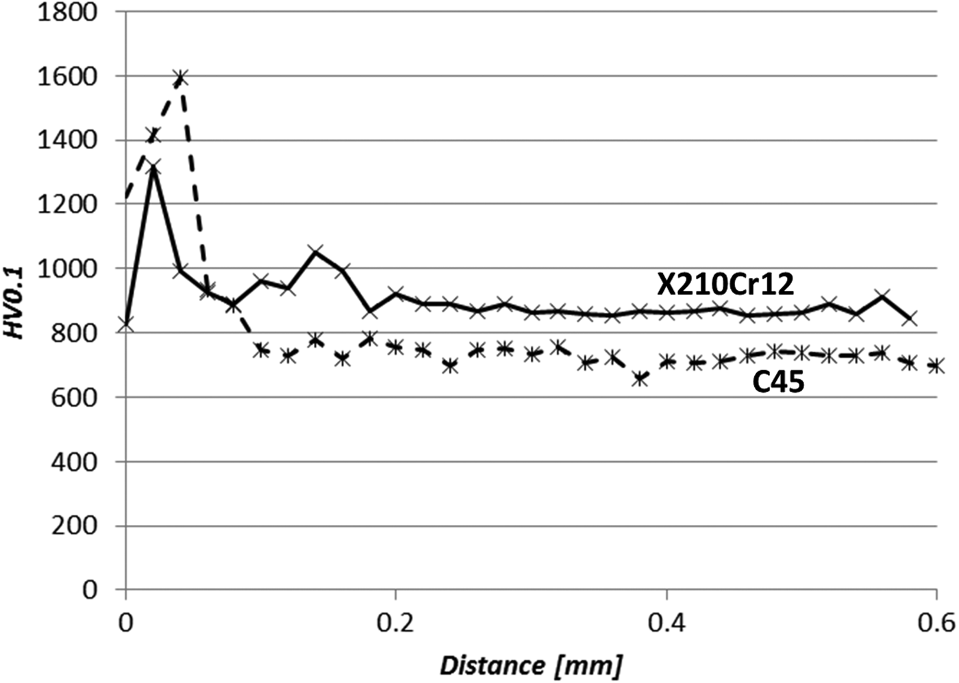
Rietveld refinements of diffraction patterns obtained on as-borided surfaces of both low- and high-alloy steels can be seen in Figures 1 and 2. Corresponding microstructures are in Figures 3 and 4 with the results of hardness measurements in Figure 5. The low-alloy as-borided surface contains only Fe2B-type boride and the thickness of the borided layer is about 80 μm; the FeB boride and oxy-borides were either not created during this process or this layer spalled off during the cooling cycle. High-alloy as-borided test piece includes on the surface dominantly oxides and oxy-borides, which are later easily removed during alumina–silica powder pressing, and both FeB and Fe2B are present. There is not sufficient information to clarify why the layer consisting of FeB, oxides, and oxy-borides did not disintegrate from the borided pieces during cooling off; however, one of the reasons could be the stronger adhesion of the FeB layer to Fe2B in the case of high-alloy steel compared with the low-alloy steel. The thickness of the boride layer in Figure 4 is not homogeneous and does not exceed 40 μm. There are dark and light “teeth” in the microstructure corresponding to variable thickness from 5 to 15 μm of the FeB layer (the darker area closer to the surface, labelled as D) and around three times thicker the Fe2B layer (the lighter area labelled as L). It is reasonable to expect that the brittle FeB layer will spall during wear. The behaviour of both experimental moulds was in a stark contrast. The soft low-alloy substrate was not able to provide support for hard borided layer and after the pressing no boride was left on the functional surface. On the contrary, the borided high-alloy steel showed limited signs of wear as only about 15 μm of the material was worn out from the surface; hence, only the brittle FeB was removed while the Fe2B was durable enough. Regarding the comparatively shallow depth of high-alloy boriding, it should be noted that some alloying elements together with carbon form a hindrance to the boron diffusion, which is in accordance with the studies of diffusion kinetics by Campos-Silva et al. (Reference Campos-Silva, Ortiz-Domínguez, Tapia-Quintero, Rodríguez-Castro, Jiménez-Reyes and Chávez-Gutiérrez2012).

Figure 1. (Color online) Rietveld refinement of pattern measured at the surface of as-borided low-alloy steel; R wp=9.2 and only Fe2B and cohenite (Fe3C) are present in the irradiated volume. Reflections of the Fe2B phase are also denoted by the Miller indices of the diffracting planes. The measured data are plotted in blue, while the fit corresponding to the refined model is in red.

Figure 2. (Color online) Rietveld refinement of pattern measured at the surface of as-borided high-alloy steel; R wp = 11.6. Apart from FeB and Fe2B, there is a richness of phases including iron oxides (magnetite and hematite), chromium oxide (eskolaite), and oxy-borides (vonsenite, Fe2BO4, and Fe2B2O5, which is labelled as “magn” in the figure).

Figure 3. Microstructure of borided low-alloy steel on the cross-section as seen by SEM (BSE-COMPO mode).

Figure 4. Microstructure of borided high-alloy steel on the cross-section as seen by SEM (BSE-COMPO mode); dark “teeth” in the microstructure are FeB grains (layer with variable thickness from 5 to 15 μm denoted by D) and thicker layer of Fe2B with lighter “teeth” (indicated by L).

Figure 5. Microhardness depth profile measured by Vickers indentor on the first stage samples' cross-sections. The step size of the measurement was 0.02 mm.
B. Elastic constants
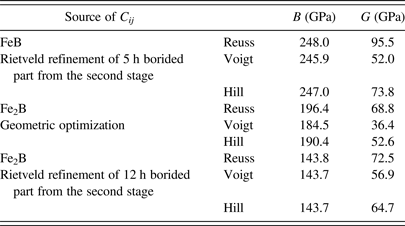
Five sets of Fe2B lattice parameters are juxtaposed in Table II; they come from the CIF file with ICSD database code of 42530 (Havinga et al., Reference Havinga, Damsma and Hokkeling1972; ICSD, 2014), our geometric optimization, geometric optimization by Zhou et al. (Reference Zhou, Xing, Xiao, Feng, Xie and Chen2009) and the Rietveld refined lattice parameter of high-alloy steel from the first stage and the 12 h borided component from the second stage. Table III contains single-crystal elastic constants of Fe2B relevant for the geometric optimization and both refined lattice sets from Table I. Analogically are listed single-crystal elastic constants of FeB in Table IV. Eventually, elastic moduli, namely isothermal bulk modulus B and shear modulus G, are listed in Table V for the Reuss, Voigt, and Hill models.
Table II. Comparison of Fe2B lattice parameters form five various sources.

Table III. Single-crystal elastic constants C ij of Fe2B computed for three sets of elastic constants.

Table IV. Single-crystal elastic constants C ij of FeB computed for two sets of elastic constants.

Table V. Isothermal bulk modulus B and shear modulus G computed from three sets of C ij .

The discrepancies between the lattice parameters of Fe2B from geometric optimization on the one side and ICSD and Rietveld refinement on the other is startling and give us the indication that RS computed from the single-crystal elastic constant from geometric optimization is not close to reality. This is also mirrored in the differences between the three sets of single-crystal elastic constants in Table III.
C. Second stage
Comparison of microstructures on the cross-section of both the 5 and 12 h borided components from the high-alloy steel can be seen in Figure 6 and it is clear that longer boriding time leads to more compact and homogeneous microstructure. The depth profile of hardness values of the borided layer reached 1500 HV and is slightly lower than the expected. Although the diffraction pattern from the surface of the object borided for 5 h contains dominantly reflections of the textured FeB phase (about 80 wt.% as seen in Figure 7), there was no brittle FeB in the XRD pattern from the surface of the 12 h borided component. In order to account for the preferred orientation in the FeB phase, the March–Dollase (Dollase, Reference Dollase1986) method for (020) and (011) diffractions was used.

Figure 6. Comparison of microstructure on the cross-section of 5 (left) and 12 (right) h borided objects showing typical “tooth-shaped” or “saw-tooth” character.

Figure 7. (Color online) Rietveld refinement of pattern measured at the surface of as-borided object borided for 5 h; R wp = 8.3. The March–Dollase method incorporated in TOPAS 4.2 was not fully able to account for strong texture in the FeB phase whose selected reflections are labelled by their Miller indices.
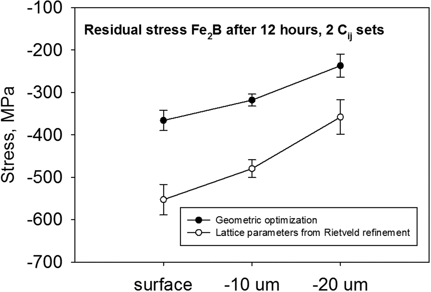
In contrast to the expectation of an oscillatory-like dependence of (212) FeB lattice spacings on sin2 ψ according to the texture seen from the Rietveld refinement in Figure 7, the plot of d 212(sin2 ψ) is linear and without splitting which lead to the FeB surface RS of −293 ± 10 MPa (using moduli from Table V corresponding to the Hill model). The RS depth distribution in the object borided for 12 h is in Figure 8. Also, the d(sin2 ψ) plots were practically linear in all three analysed depths of the boride layer and this corresponds to the fact that Rietveld refinement of the corresponding pattern did not call for any texture-related algorithms. For comparison, in Figure 8 are plotted also the stresses computed with moduli according to the Hill model for geometric optimization and lattice parameters refined by the Rietveld method. The differences between both approaches to elastic constant calculation are demonstrated by big discrepancy in RS values. Both sets of C ij led to compressive RS throughout the whole borided layer with compressive stresses diminishing in their value with increasing distance from the original free surface. The difference in elastic constants introduces shifts to the compressive magnitude of calculated RS. The fact that RS retains compressive character throughout the boride layer should be also beneficial for the practical usage and should further enhance the component durability. What remains to be done is the analysis of RS field in the area around the interface between the borided layer and substrate and also in the substrate itself. The prospective effects of RS present in the object prior to the boriding process still remain to be quantified, because the thermal RS relief is not routinely performed before boriding.

Figure 8. Juxtaposition of RS depth distributions obtained for using two sets of single-crystal elastic constants.
IV. CONCLUSIONS
The coupled analysis of microstructure and hardness together with phase composition and RS in low- and high-alloy borided steels enables us to make the following conclusions.
-
• Boriding of low-alloy C45 steel leads to the relatively thick Fe2B layer, but the high levels of wear and imposed stress during pressing of highly-abrasive materials renders the hard boride layer on soft substrate an unsuitable system.
-
• On the other hand, the same boriding conditions applied to high-alloy X210Cr12 steel lead to the FeB-cum-Fe2B boride layer which does withstand the extreme wear. Only the FeB layer is worn out and the remaining layer furnishes sufficient protection even though the boride layer has less homogeneous microstructure than in the case of borided C45 steel.
-
• Single-crystal elastic constants of both Fe2B and FeB computed according to the geometric optimization differ markedly from those computed by the quantum mechanical approach with lattice parameters taken as fixed from Rietveld refinement. The difference in elastic constants introduces shifts to the compressive magnitude of calculated RS. Hence, the approach taking advantage of Rietveld refinement should give more plausible elastic constants.
-
• Boriding is capable of creating the Fe2B layer with compressive stresses throughout the whole hardened layer with maximum stresses near the free surface and with increasing depth diminishing their value, but still attaining beneficial compressive character.
ACKNOWLEDGEMENTS
The corresponding author and JK, LB, and KK gratefully acknowledge the support of the Technology Agency of the Czech Republic within the frame of the project TA02011367. JF, TK, and JC acknowledge the support of the Czech Science Foundation through project number 14-36566G entitled Multidisciplinary Research Centre for Advanced Materials.


