1 Introduction
As one of the major approaches to achieve controllable fusion ignition, laser driven inertial confinement fusion (ICF) has been widely studied around the world[Reference Basov1–Reference Bodner, McCrory and Afeyan4]. As essential drivers, several huge laser facilities have been constructed, such as the National Ignition Facility (NIF) in the United States[Reference Haynam, Auerbach, Bowers, Dixit, Erbert, Heestand, Henesian, Hermann, Jancaitis, Manes, Marshall, Mehta, Menapace, Moses, Murray, Nostrand, Orth, Patterson, Sacks, Shaw, Spaeth, Sutton, Williams, Widmayer, White, Yang and Van Wonterghem5], the laser megajoule (LMJ) in France[Reference Garrec6] and the SG-III laser facility in China[Reference Deng, Zhu, Zheng, Wei, Jing, Hu, Zhou, Feng, Wang, Peng, Liu, Chen, Ding, Lin, Guo and Dang7]. These laser facilities are designed to provide timely tailored ultraviolet laser driving during as long as tens of nanoseconds, producing x-ray radiation in a hohlraum which then compresses DT pellet to achieve fusion ignition[Reference Bodner, McCrory and Afeyan4]. In order to deliver more energy onto the target, the lasers have to be converted to ultraviolet, and wavelength tuning is required to avoid energy loss. Typically, fusion level laser facilities are designed to output MJ level laser energy. NIF has 192 laser beamlines, providing 1.8 MJ laser energy. LMJ also has 1.8 MJ designed output capability with 240 beamlines. The SG-III laser facility is the largest laser driver in China at present, which is designed to deliver 180 kJ ultraviolet laser energy onto the target, exploring the key physics processes and the technologies of ICF, while not to achieve fusion ignition.
The engineering construction of the SG-III laser facility started in 2007, lasting nearly 8 years, and met its goal of generating 180 kJ![]() $/$3 ns
$/$3 ns![]() $/$351 nm laser energy in 2015. The whole laser facility was designed and collectively integrated by Laser Fusion Research Center in China Academy of Engineering Physics. In the past 8 years, this largest laser facility in China has involved nearly 200 institutes, universities and companies as vendor, and several thousands of scientists, engineers, technicians and skilled laborers have worked for it. The first shot in SG-III with its full output capability was conducted in 14 September 2015, in which shot the output 351 nm ultraviolet laser energy reached 181.3 kJ, exceeding its designed point for the first time. This meaningful shot indicated that China had finished the engineering construction of the 100 kJ level ICF research platform and the SG-III laser facility established its world second output capability currently.
$/$351 nm laser energy in 2015. The whole laser facility was designed and collectively integrated by Laser Fusion Research Center in China Academy of Engineering Physics. In the past 8 years, this largest laser facility in China has involved nearly 200 institutes, universities and companies as vendor, and several thousands of scientists, engineers, technicians and skilled laborers have worked for it. The first shot in SG-III with its full output capability was conducted in 14 September 2015, in which shot the output 351 nm ultraviolet laser energy reached 181.3 kJ, exceeding its designed point for the first time. This meaningful shot indicated that China had finished the engineering construction of the 100 kJ level ICF research platform and the SG-III laser facility established its world second output capability currently.
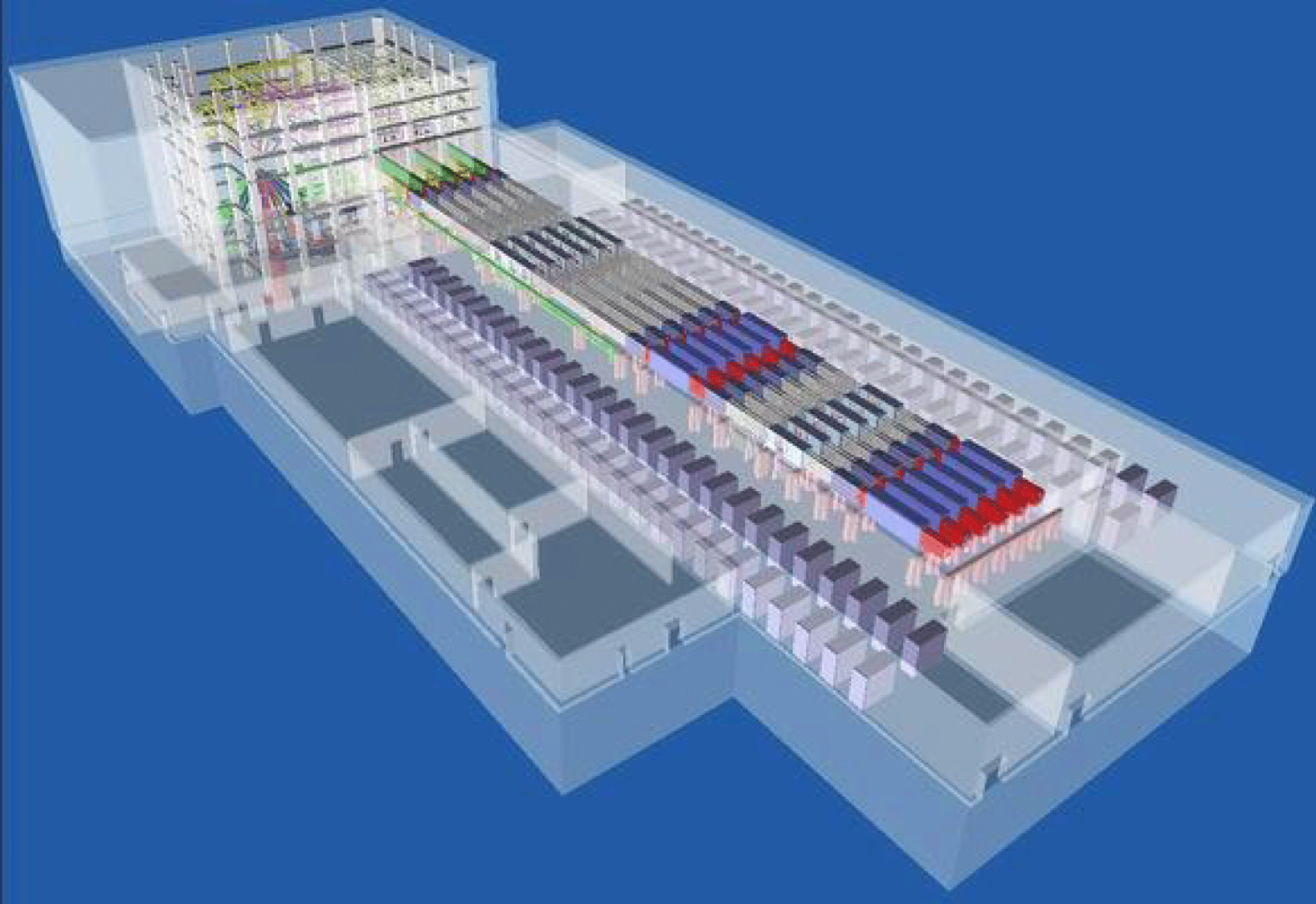
Figure 1. Schematic of the SG-III laser facility.
In this paper, we briefly review the laser system and then introduce the SG-III laser performance in detail. After precise adjustment, the whole laser facility has met all the design requirements, such as the 180 kJ energy and 60 TW power ultraviolet output capability, ![]() $30~{\rm\mu}\text{m}$ pointing precision, 10 ps synchronization level (root mean square (RMS) value), 10% power balance level (RMS value), pulse shaping capability and so on, which form solid foundations for deeper ICF researches in China.
$30~{\rm\mu}\text{m}$ pointing precision, 10 ps synchronization level (root mean square (RMS) value), 10% power balance level (RMS value), pulse shaping capability and so on, which form solid foundations for deeper ICF researches in China.
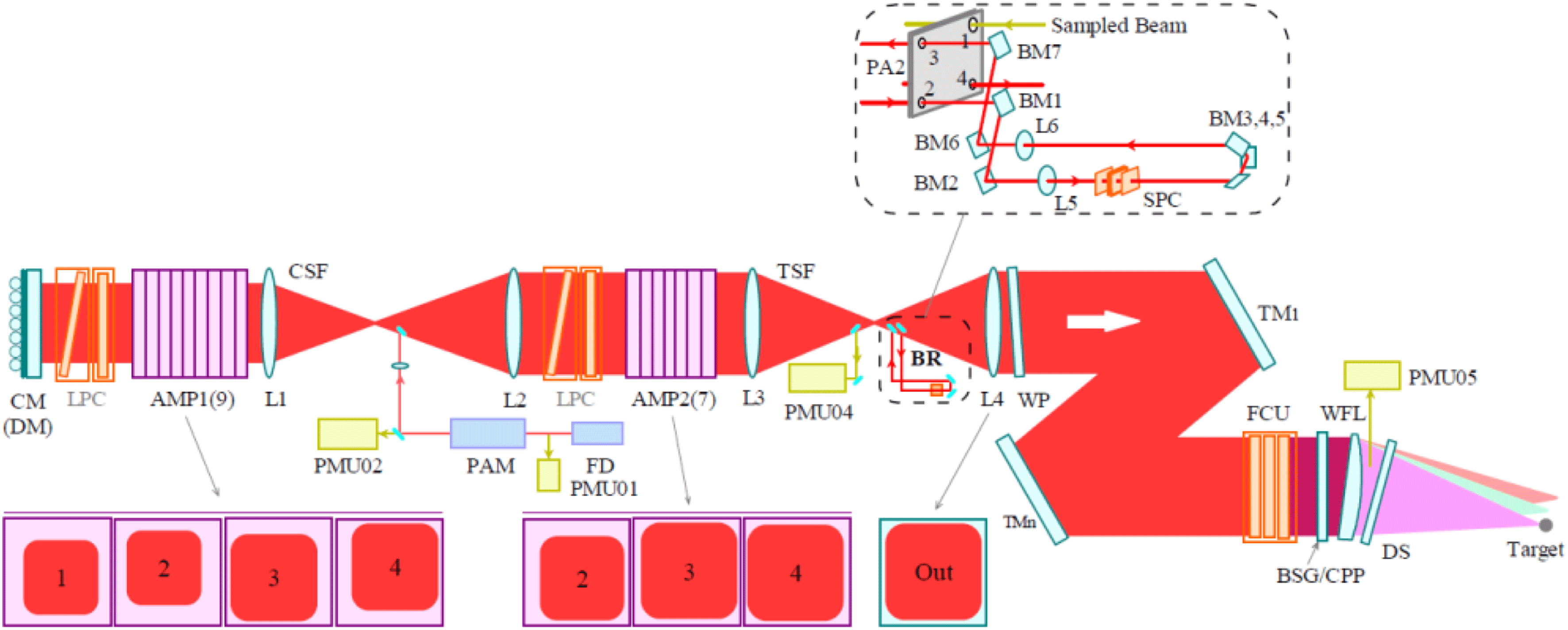
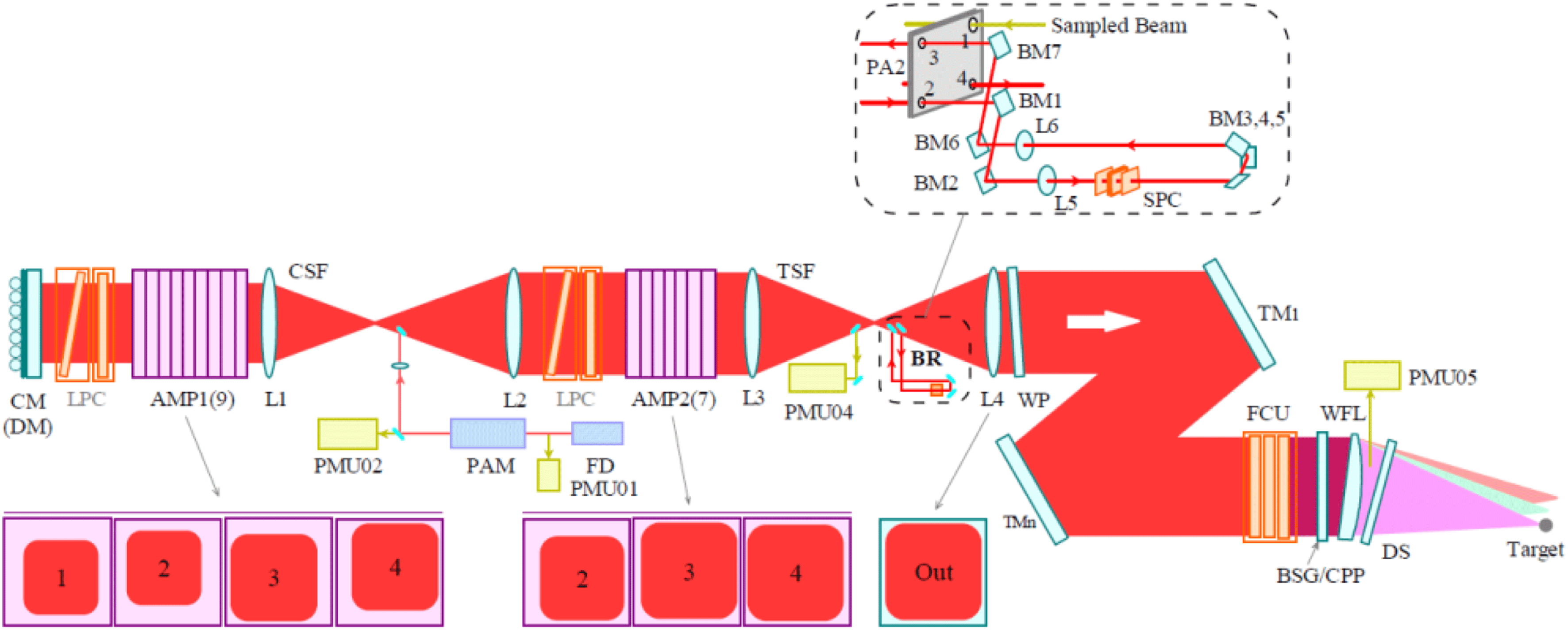
Figure 2. Schematic of one of the 48 beamlines in the SG-III laser facility. CM: cavity mirror; DM: deformable mirror; AMP: amplifier plate; L: lens; CSF/TSF: cavity/transport spatial filter; WP: wedge plate; TM: transport mirror; FCU: frequency conversion unit; BSG: beam sampling grating; CPP: continuous phase plate; WFL: wedged focus lens; PMU: parameter measurement unit; DS: debris shield; FD: front end; PAM: preamplifier; LPC: large pockels cell; BM: beam mirror; BR: beam reverser.

Figure 3. The schematic of the U-tum reverser and its influence on the wavefront distortion.

Figure 4. Schematics of the two adaptive optics systems in SG-III laser facility.
2 System configuration
The SG-III laser facility possesses 48 laser beams, which are divided into six bundles with ![]() $4\times 2$ beam arrangement (Figure 1). The whole laser facility is placed in a cleanness-maintained laboratory as large as two standard football fields and generally divided into six sub-systems as front-end system, preamplifier system, main amplifier system, target area system, diagnostics and beam control system, and supervisory control system. The SG-III laser facility is a typical great science engineering project representing the highest development of a series of subjects in China, such as optics, lasers, pulsed power, fine mechanics, fast electronics, automatic control, chemical cleaning, ultra-precision machining and so on.
$4\times 2$ beam arrangement (Figure 1). The whole laser facility is placed in a cleanness-maintained laboratory as large as two standard football fields and generally divided into six sub-systems as front-end system, preamplifier system, main amplifier system, target area system, diagnostics and beam control system, and supervisory control system. The SG-III laser facility is a typical great science engineering project representing the highest development of a series of subjects in China, such as optics, lasers, pulsed power, fine mechanics, fast electronics, automatic control, chemical cleaning, ultra-precision machining and so on.
A schematic of one laser beamline of the SG-III is shown in Figure 2 (the abbreviations are listed in the caption). Laser pulse of 1053 nm wavelength with nJ level energy is firstly generated in the front-end system, where the laser temporal profile and frequency are also modulated. Then it is preamplified to about J level in the PAM and injected into the main amplifier. Laser pulse will pass the AMP1 four times and the AMP2 three times, during which, the laser size is gradually enlarged and finally reaches ![]() $360~\text{mm}\times 360~\text{mm}$, and the energy is amplified up to 7.5 kJ. After propagation in the switchyard, the laser pulse is finally injected into the final optics assembly (FOA), where, it is frequency tripled to 351 nm and focused to the target. The wedged focus lens isolates the rest fundamental and doubled frequencies from the target. Parameter measurement units distribute in different parts of the beamline, which provide sufficient laser information. The operation of the whole laser system is controlled by the supervisory control system, which insures the synchronization of the 48 beamlines. Detailed information of the sub-systems can be obtained from early references[Reference Peng, Zhang, Wei, Zheng, Jing, Sui, Zhao, Fan, Ling and Zhou8, Reference Yao, Liu, Guo, Tang, Ran and Zhou9].
$360~\text{mm}\times 360~\text{mm}$, and the energy is amplified up to 7.5 kJ. After propagation in the switchyard, the laser pulse is finally injected into the final optics assembly (FOA), where, it is frequency tripled to 351 nm and focused to the target. The wedged focus lens isolates the rest fundamental and doubled frequencies from the target. Parameter measurement units distribute in different parts of the beamline, which provide sufficient laser information. The operation of the whole laser system is controlled by the supervisory control system, which insures the synchronization of the 48 beamlines. Detailed information of the sub-systems can be obtained from early references[Reference Peng, Zhang, Wei, Zheng, Jing, Sui, Zhao, Fan, Ling and Zhou8, Reference Yao, Liu, Guo, Tang, Ran and Zhou9].
There are two distinct techniques adopted in SG-III laser facility. The first one is the U-tum beam reverser. As shown in Figure 3, with the U-tum reverser, the near-field of the laser beam is rotated by ![]() $90^{\circ }$ when reflected back. This simple rotation brings at least three advantages. Firstly, it transfers the positively overlapped hot distortion to defocusing, which can be easily eliminated by the optical lens. Secondly, it can eliminate the positive wavefront distortion overlap cause by the optics. And thirdly, this rotation can mitigate the gain nonuniformity of the amplifier plates. Above all, this
$90^{\circ }$ when reflected back. This simple rotation brings at least three advantages. Firstly, it transfers the positively overlapped hot distortion to defocusing, which can be easily eliminated by the optical lens. Secondly, it can eliminate the positive wavefront distortion overlap cause by the optics. And thirdly, this rotation can mitigate the gain nonuniformity of the amplifier plates. Above all, this ![]() $90^{\circ }$ U-tum design is quite useful for current beam quality control and suitable for small pockels cells during laser amplification.
$90^{\circ }$ U-tum design is quite useful for current beam quality control and suitable for small pockels cells during laser amplification.
The other distinct technique in SG-III laser facility is that there are two adaptive optics systems (Figure 4). In other words, there are two deformable mirrors in one beamline in the SG-III. One works as the cavity mirror in the beamline. The other works as the last transport mirror in the beamline, which reflects the laser into the FOA and the chamber. For the cavity deformable mirrors, there are corresponding Shack–Hartmann sensors set in the diagnostic package working with them, which detect the fundamental wavefront distortions at the position of the L4 lens. For the last transport deformable mirrors, only one Shack–Hartmann sensor set in the center of the target chamber works with them, which can be freely rotated and aligned to any beamline. This Shack–Hartmann sensor only detects the wavefront distortion of the tripled frequency.
There is no large pockels cell in the SG-III, effectively evading the difficulty of manufacturing qualitative large pockels cells and their damage as NIF[Reference Arnold, Ollis, Hinz, Robb, Primdahl, Watson, O’Brien, Funkhouser, Biltoft, Shelton, Tapley and DeHope10]. Also, by adopting the U-tum reverser and letting the light pass the transport amplifier for only three times, the space problem encountered by LMJ is also resolved in the SG-III. With a system transmittance upper than 70%, 100,000 times amplification and about 10 kJ ![]() $1{\it\omega}$ output is realized without large pockels cells, which greatly increases the cost performance of the SG-III laser facility.
$1{\it\omega}$ output is realized without large pockels cells, which greatly increases the cost performance of the SG-III laser facility.

Figure 5. The tested result of the small signal gain coefficients of each beamline in SG-III.

Figure 6. Experimental results of the 7.5 kJ ![]() $1{\it\omega}$ output capability.
$1{\it\omega}$ output capability.

Figure 7. 7-hour test of the energy stability in front-end system.
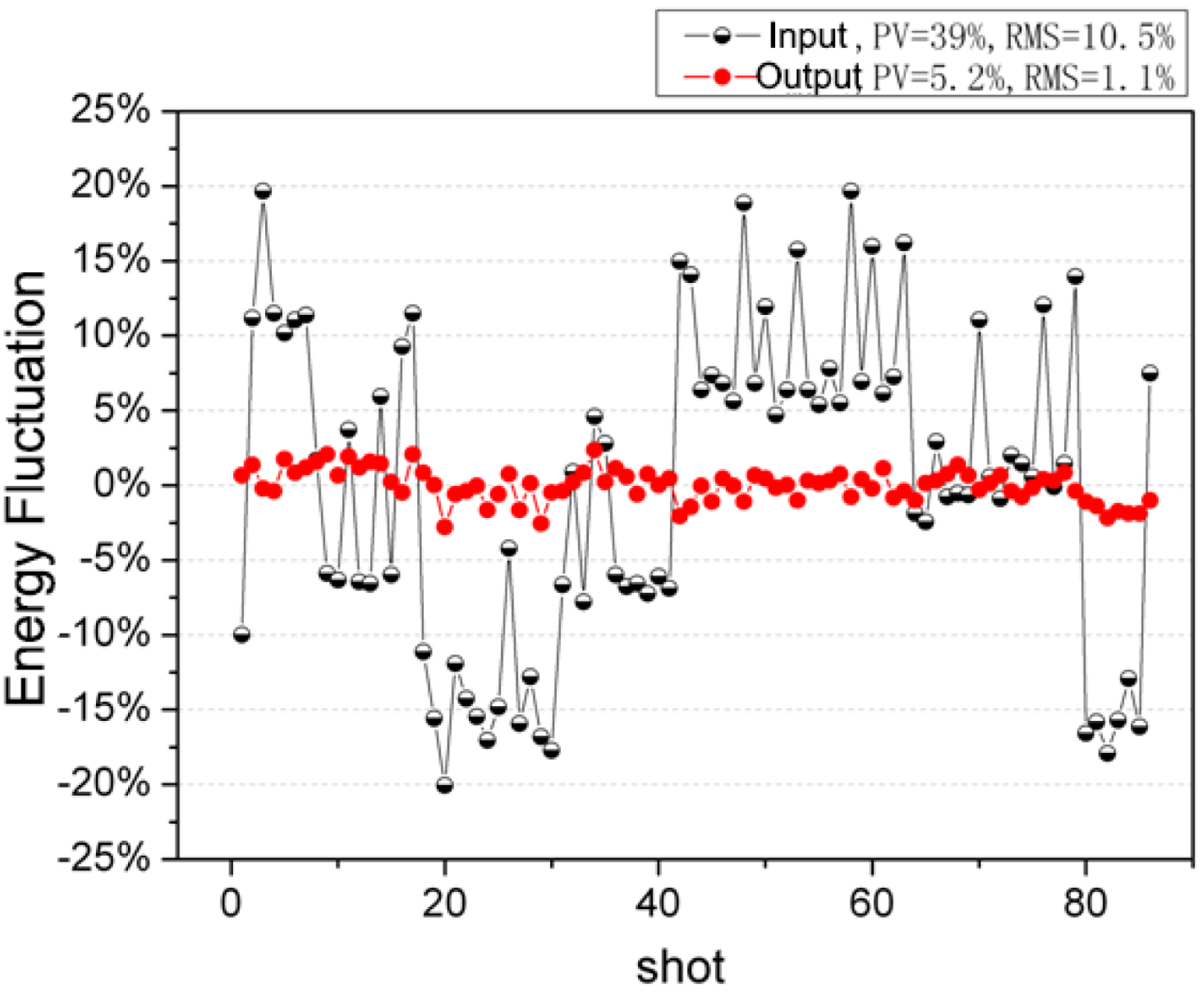
Figure 8. Energy stabilizing result in preamplifier system.
3 Laser performance
During SG-III’s engineering construction, most eyesight is focused on its output capability, because this index is the most important one to evaluate the technical development of the SG-III when compared with the earlier laser facilities[Reference Li, Zhao, Wang, Geng, Pu and Su11, Reference Lin, Deng, Fan, Wang, Chen, Zhu, Qian, Shen, Xu, Zhu, Ma, Xie, Zheng, Zhang, Chen, Ling, Huang and Zhang12]. The energy store ratio of the main amplifier can be expressed as
where ![]() $E_{\text{sat}}$ is the saturated energy of the gain medium,
$E_{\text{sat}}$ is the saturated energy of the gain medium, ![]() $g_{0}$ is the small signal gain coefficient,
$g_{0}$ is the small signal gain coefficient, ![]() $V_{\text{slab}}$ is the effective pump volume,
$V_{\text{slab}}$ is the effective pump volume, ![]() $E_{\text{pump}}$ is the pump energy,
$E_{\text{pump}}$ is the pump energy, ![]() $n_{0}$ is the inverted population density,
$n_{0}$ is the inverted population density, ![]() $h$ is the Planck constant,
$h$ is the Planck constant, ![]() ${\it\nu}$ is the laser frequency. Under some certain pumping condition, the small signal gain coefficient
${\it\nu}$ is the laser frequency. Under some certain pumping condition, the small signal gain coefficient ![]() $g_{0}$ is linearly related to the pump energy
$g_{0}$ is linearly related to the pump energy ![]() $E_{\text{pump}}$. In the SG-III laser facility, the tested result of the small signal gain coefficient of each beamline is shown in Figure 5. With the 23.5 kV pumping voltage, the small signal gain coefficient reaches
$E_{\text{pump}}$. In the SG-III laser facility, the tested result of the small signal gain coefficient of each beamline is shown in Figure 5. With the 23.5 kV pumping voltage, the small signal gain coefficient reaches ![]() $5.02\%~\text{m}^{-1}$. Since the stored energy density of the amplifier is decided by
$5.02\%~\text{m}^{-1}$. Since the stored energy density of the amplifier is decided by
where ![]() ${\it\sigma}$ is the absorption cross-section (
${\it\sigma}$ is the absorption cross-section (![]() $3.9\times 10^{-20}~\text{cm}^{2}$ for Nd:glass). So the stored energy density for each single Nd:glass plate is
$3.9\times 10^{-20}~\text{cm}^{2}$ for Nd:glass). So the stored energy density for each single Nd:glass plate is ![]() $0.24~\text{J}~\text{cm}^{-2}$. Considering the effective size of the Nd:glass of
$0.24~\text{J}~\text{cm}^{-2}$. Considering the effective size of the Nd:glass of ![]() $784~\text{mm}\times 434~\text{mm}\times 40~\text{mm}$, it is easy to obtain the stored energy in single plate of 3.285 kJ. Figure 6 gives the results of the designed 7.5 kJ
$784~\text{mm}\times 434~\text{mm}\times 40~\text{mm}$, it is easy to obtain the stored energy in single plate of 3.285 kJ. Figure 6 gives the results of the designed 7.5 kJ ![]() $1{\it\omega}$ energy output demonstration. With six main shots, the averaged output
$1{\it\omega}$ energy output demonstration. With six main shots, the averaged output ![]() $1{\it\omega}$ energy of each bundle is stable around the designed energy point and the energy dispersion is kept below 5%.
$1{\it\omega}$ energy of each bundle is stable around the designed energy point and the energy dispersion is kept below 5%.

Figure 9. The experimental gain curve in the main amplifiers in SG-III.
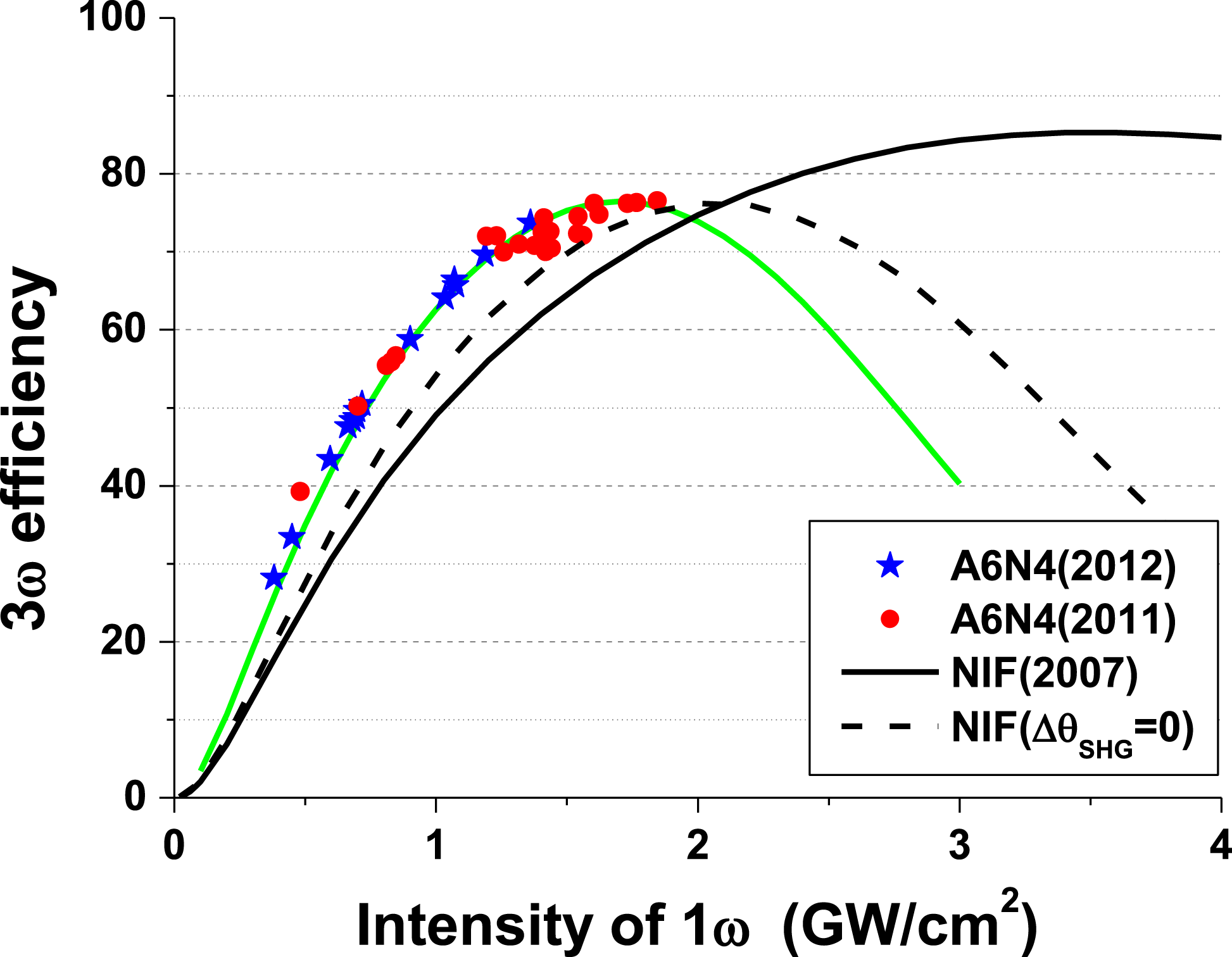
Figure 10. The frequency conversion curve tested in A6N4.
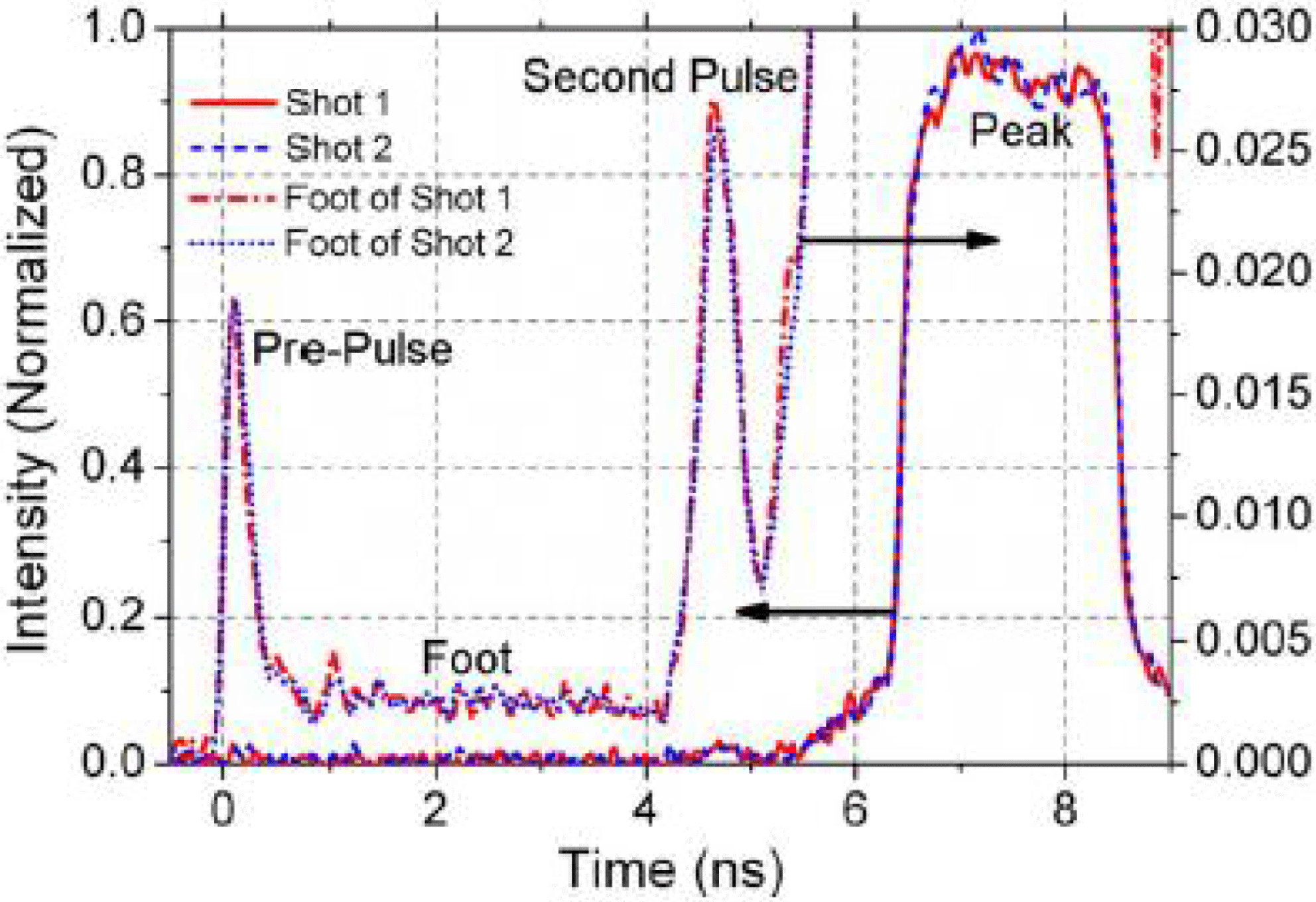
Figure 11. Complex pulse shape with ![]() $300:1$ contrast ratio in SG-III. Reproduced from Ref. [Reference Hu, Dong, Xu, Huang, Zhou, Tian, Zhou, Guo, Zhong, Deng, Zhu and Zheng13].
$300:1$ contrast ratio in SG-III. Reproduced from Ref. [Reference Hu, Dong, Xu, Huang, Zhou, Tian, Zhou, Guo, Zhong, Deng, Zhu and Zheng13].

Figure 12. Experimental result of the pre-compensation for the FM-to-AM effect.
Laser power balance not only represents the overall performance of the laser facility, but also is an important index for the ICF target physics processes. During the compression process, power balanced laser driving leads to symmetrical implosion, while power imbalanced laser driving results in asymmetrical energy deposition so that the fuels cannot be efficiently compressed and ignition fails. Laser energy stability is a key factor for the final power balance, so the laser energy fluctuation must be carefully controlled during laser propagation and amplification. For example, NIF use a regenerative amplifier to keep the energy stability of about 2.2% in the injection laser system[Reference Haynam, Auerbach, Bowers, Dixit, Erbert, Heestand, Henesian, Hermann, Jancaitis, Manes, Marshall, Mehta, Menapace, Moses, Murray, Nostrand, Orth, Patterson, Sacks, Shaw, Spaeth, Sutton, Williams, Widmayer, White, Yang and Van Wonterghem5]. While in the SG-III laser facility, the high-gain preamplifier scheme is quite different from that of the regenerative amplifier, so a different method is proposed to stabilize the laser energy. In the front-end system, all the fiber elements that may contribute to the energy instability are carefully checked, such as the CW fiber amplifier, the polarization stabilizer, the polarization maintained fiber and so on. The energy output stability from the front-end system is shown in Figure 7. The test is made

Figure 13. Smoothing effect by CPP and ![]() $2.5~\text{GHz}+19.9~\text{GHz}$ SSD. Left: initial focal spot; Right: smoothed focal spot.
$2.5~\text{GHz}+19.9~\text{GHz}$ SSD. Left: initial focal spot; Right: smoothed focal spot.
in bundle A5. During the 7-h test, the PV value is 5.92 and the RMS value is 0.53%. In the preamplifier system, an active energy stabilizing method is adopted. With a pre-detection of the pulse energy fluctuation, the transmittance of the pockels cells is changed inversely in order to stabilize the final output energy of the preamplifier system. Figure 8 shows the stabilizing result in preamplifier system. With the input energy fluctuating strongly, the output energy is stabilized to PV 5.2% and RMS 1.1%. This instability will transfer to the main amplification and frequency conversion processes; in these two processes, the pulse energy transferring is relatively stable, as shown in Figures 9 and 10. So finally the ![]() $3{\it\omega}$ energy balance is kept below 10%.
$3{\it\omega}$ energy balance is kept below 10%.

Figure 14. Measured focal spot patterns. (a) 2D pattern only with CPP, (b) 1D pattern only with CPP, (c) 2D pattern both with CPP and PS crystal, (d) 1D pattern both with CPP and PS crystal. Reproduced from Ref. [Reference Huang, Jia, Zhou, Zhang, Guo and Deng18].
Pulse shaping capability is another key factor for power balance and is also tested in the SG-III laser facility. As shown in Figure 11, the test result reveals excellent repeat of the pulse shape and a high contrast ratio of 300:1[Reference Hu, Dong, Xu, Huang, Zhou, Tian, Zhou, Guo, Zhong, Deng, Zhu and Zheng13]. However, in high-power lasers, the spectra loss during laser propagation and amplification results in serious FM-to-AM (frequency modulation to amplitude modulation) effect, that not only affects the laser pulse shape, but also threatens the operation safety of the laser facility. A pre-compensation method is adopted in the front-end system in SG-III, which makes an artificial transmittance curve exactly compensating the real system transmittance curve. The result is shown in Figure 12: FM-to-AM effect is well suppressed, and the amplitude modulation is kept below 5%. With the energy stability and the precise pulse shape control, the demonstrated power balance in SG-III is 9.2% with a constant-temperature pulse shape.
Beam smoothing techniques, such as continuous phase plate (CPP), smoothing by spectral dispersion (SSD)[Reference Rui, Xiaomin, Zhan, Jingqin, Wenyi, Honghuan and Lanqin14, Reference Rui, Xiaomin, Jingqin, Zhan, Honghuan, Feng and Wenyi15] and polarization smoothing (PS)[Reference Rothenberg16–Reference Huang, Jia, Zhou, Zhang, Guo and Deng18], are all adopted in SG-III. When CPP and SSD are both used, the focal spot is obviously smoothed and the nonuniformity of the focal spot is reduced from 1.21 to 0.27 (Figure 13). PS can further smooth the focal spot by a factor of 0.717 theoretically. A KDP plate is used in the focusing beam section in SG-III to induce PS[Reference Huang, Jia, Zhou, Zhang, Guo and Deng18]. The smoothing results are shown in Figures 14 and 15. With a PS plate in the converging beam section, the focal spot is smoothed and the FOPAI curve of the spot clearly reveals the PS effect.
The AO system before the target chamber effectively improves the ![]() $3{\it\omega}$ focal spot quality. As shown in Figure 16, after wavefront is corrected by the deformable mirror, the
$3{\it\omega}$ focal spot quality. As shown in Figure 16, after wavefront is corrected by the deformable mirror, the ![]() $3{\it\omega}$ focal spots are focused much better than without the adaptive optics (AO) correction. This improvement insures the laser energy injection into the hohlraum, reducing the threat of the side beam interacting with the hole that pretends the following lasers entering the hohlraum.
$3{\it\omega}$ focal spots are focused much better than without the adaptive optics (AO) correction. This improvement insures the laser energy injection into the hohlraum, reducing the threat of the side beam interacting with the hole that pretends the following lasers entering the hohlraum.
The SG-III laser facility is designed to provide 600 shots per year. In the last quarter of 2015, it provides more than 120 shots for physics experiments. This operation efficiency cannot yet meet the designed requirement. However, considering the situation that the SG-III laser facility has just been constructed, numerous adjusting and updating jobs are still undergoing, this operation efficiency is quite amazing and it is believed that the operation efficiency can meet the designed requirement soon.

Figure 15. PS effect calculated by FOPAI curves. Reproduced from Ref. [Reference Huang, Jia, Zhou, Zhang, Guo and Deng18].

Figure 16. Correction effect of the AO system. (a) and (b) give the ![]() $3{\it\omega}$ focal spots on the target before and after AO correction, and (c) shows the wavefront distortion value of the whole 48 beamlines before and after AO correction.
$3{\it\omega}$ focal spots on the target before and after AO correction, and (c) shows the wavefront distortion value of the whole 48 beamlines before and after AO correction.
4 Conclusion
The SG-III laser facility is now the largest in China and the world’s second laser driver. It can provide 180 kJ ultraviolet laser energy with flexible tuning parameters, which will be the most important ICF research platform for China. A lot of new technologies have been adopted in this laser facility, which have been demonstrated useful for physics experiments and laser technology itself. The great progresses in the laser performance and the physics experiments have already demonstrated that the facility is in excellent accordance with the designs, which establish a solid foundation for completing all the construction goals and finally become the most important platform for ICF researches in China at present. Although the SG-III laser facility cannot achieve fusion ignition due to its energy limitation, it can still provide enough experimental capabilities for decomposed ICF key physics process studies. These studies will support future ICF researches not only in China, but also around the world. The SG-III laser facility will provide valuable experiences not only for laser design and engineering, but also for our understanding of ICF physics.


