Hostname: page-component-586b7cd67f-gb8f7 Total loading time: 0 Render date: 2024-11-24T21:57:09.582Z Has data issue: false hasContentIssue false

New momentum integral equation applicable to boundary layer flows under arbitrary pressure gradients

Published online by Cambridge University Press:  11 April 2024

Tie Wei*
Affiliation:
Department of Mechanical Engineering, New Mexico Tech, 801 Leroy Place, Socorro, NM 87801, USA
Zhaorui Li
Affiliation:
Department of Engineering, Texas A&M University-Corpus Christi, 6300 Ocean Drive, Corpus Christi, TX 78412, USA
Yanxing Wang
Affiliation:
Department of Mechanical and Aerospace Engineering, New Mexico State University, 1780 E University Avenue, Las Cruces, NM 88003, USA
*
Email address for correspondence: [email protected]

Abstract

By incorporating the traditionally overlooked advective term in the wall-normal momentum equation, a new momentum integral equation is developed for two-dimensional incompressible turbulent boundary layers under arbitrary pressure gradients. The classical Kármán's integral arises as a special instance of the new momentum integral equation when the pressure gradient is weak. The new momentum integral equation's validity is substantiated by direct numerical simulation data. Unlike the classical Kármán's integral, which is limited to predicting wall shear stress within mild pressure gradients, the new momentum integral equation accurately computes wall shear stress across a broad range of pressure gradients, even in the presence of strong adverse pressure gradients that lead to flow separation. Moreover, a new pressure parameter $\beta _\kappa$ is introduced through examining terms in the new momentum integral equation. This parameter naturally quantifies the pressure gradient's influence on turbulent boundary layers and offers guidance for applying the classical Kármán's integral. Additionally, to facilitate experimental determination of wall shear stress under strong pressure gradients, an approximate integral equation is proposed that relies solely on easily measurable variables. Validation against direct numerical simulation data demonstrates that this simplified equation provides reasonably accurate estimates of wall shear stress in turbulent boundary layers experiencing strong pressure gradients.

Type
JFM Papers
Copyright
© The Author(s), 2024. Published by Cambridge University Press

1. Introduction

Pohlhausen (Reference Pohlhausen1921), von Kármán (Reference von Kármán1921) and Gruschwitz (Reference Gruschwitz1931) pioneered integral analysis of the momentum equation in boundary layer flows, leading to the discovery of the momentum integral equation – a significant advancement in the field (see Schlichting Reference Schlichting1979). The classic form of the momentum integral equation is expressed as follows (refer to (8.32) in Schlichting (Reference Schlichting1979)):

(1.1)\begin{equation} \frac{\tau_{wall}}{\rho} \approx U_e \frac{\mathrm{d} U_e}{\mathrm{d}\kern0.06em x} \delta_1 + \frac{\mathrm{d}(U^2_e \delta_2)}{\mathrm{d}\kern0.06em x}, \end{equation}

where $\tau _{wall}$ is the wall shear stress, $\rho$ is the fluid density, $U_e$ is the mean streamwise velocity at the boundary layer edge, $\delta _1$ is the mass displacement thickness and $\delta _2$ is the momentum thickness. The momentum integral equation in the form of (1.1) was first developed by Gruschwitz (Reference Gruschwitz1931), as noted by Schlichting (Reference Schlichting1979). However, in the literature, (1.1) is often referred to as Kármán's integral, for example in the books by Pope (Reference Pope2000) and Kundu, Cohen & Dowling (Reference Kundu, Cohen and Dowling2012).

The classical momentum integral equation, commonly employed in previous studies, is derived under assumptions suitable for boundary layer flows with mild pressure gradients. However, these assumptions break down for flows under strong adverse pressure gradients, making Kármán's integral ineffective in predicting wall shear stress, as demonstrated in figure 1. The figure compares Kármán's integral with the directly calculated wall shear stress obtained from the direct numerical simulation (DNS) conducted by Coleman, Rumsey & Spalart (Reference Coleman, Rumsey and Spalart2018). The DNS covers a family of boundary layer flows that contain a small separation bubble. The pressure gradients were induced by a transpiration profile $V_{top}(x)$ acting through a virtual parallel plane offset a fixed distance $Y$ from the flat no-slip surface. Each simulation consists of a well-developed entry region with a negligible pressure gradient, followed by an adverse pressure gradient and then a favourable pressure gradient. For evaluation, we consider Case C of simulations, which is accessible in the NASA repository. Based on friction coefficient data, turbulent boundary layer separates at $x/Y \approx -1.4$ and subsequently reattaches at $x/Y \approx 0.4$. Using pressure gradient data, the favourable pressure gradient region begins approximately at $x/Y \approx 0.87$ (see Coleman et al. Reference Coleman, Rumsey and Spalart2018).

Figure 1. (a) Comparison between Kármán's integral and the directly computed wall shear stress from the DNS data of Coleman et al. (Reference Coleman, Rumsey and Spalart2018). (b) Variation of the Rotta–Clauser pressure gradient parameter along the $x$ direction. Vertical dashed lines indicate $x$ positions with $|\beta _{RC}|=10$. The larger $\beta _{RC}$ values around the separation region are shown in figure 3. The streamwise location is normalized by the simulation domain height in the wall-normal direction, denoted as $Y$.

Figure 1(b) illustrates the variation of the Rotta–Clauser pressure gradient parameter $\beta _{RC}$ along the $x$ direction. Widely employed in the investigation of turbulent boundary layer under pressure gradient, $\beta _{RC}$ is defined as $(\delta _1/\tau _{wall})({\rm d}P/{{\rm d}\kern0.06em x})$ (Clauser Reference Clauser1954). In regions under mild pressure gradients, where $|\beta _{RC}| \ll 10$ (e.g. $-13 < x/Y < -8$ in the DNS data), classical Kármán's integral accurately predicts wall shear stress, as shown in figure 1. However, in the presence of strong adverse pressure gradients, the traditional Kármán's integral proves inadequate for predicting wall shear stress.

An effort to extend Kármán's integral equation was made by Coleman et al. (Reference Coleman, Rumsey and Spalart2018), who integrated the $x$-momentum equation from the inflow station to an arbitrary location $x$. The resultant mean integral–momentum balance consists of the conventional two terms involving $\delta _1$ and $\delta _2$ in (1.1), as well as three additional terms that account for turbulence effects and pressure variations within the boundary layer. While these additional terms are often negligible under boundary layer assumptions, they become significant for flows subject to strong adverse pressure gradients (see Appendix C in Coleman et al. (Reference Coleman, Rumsey and Spalart2018)).

In this work, we derive a general momentum integral equation that is applicable to boundary layer flows under arbitrary pressure gradients. By removing the limitations of the conventional momentum integral analysis, this new equation provides a more accurate representation of boundary layer flows across a broader range of conditions.

2. New momentum integral equation for boundary layer flows

The governing equations for a statistically two-dimensional incompressible turbulent boundary layer flow are (e.g. Townsend Reference Townsend1956; Schlichting Reference Schlichting1979; Pope Reference Pope2000)

(2.1)$$\begin{gather} 0 = \frac{\partial U}{\partial x} + \frac{\partial V}{\partial y}, \end{gather}$$
(2.2)$$\begin{gather}0 = {-U\frac{\partial U}{\partial x}-V\frac{\partial U}{\partial y}} + {\nu \frac{\partial^2 U}{\partial x^2} +\nu \frac{\partial^2 U}{\partial y^2}} + {\frac{\partial R_{uu}}{\partial x} + \frac{\partial R_{uv}}{\partial y}} {-\frac{\partial}{\partial x}\left(\frac{P}{\rho} \right)}, \end{gather}$$
(2.3)$$\begin{gather}0 = {-U\frac{\partial V}{\partial x}-V\frac{\partial V}{\partial y}} + {\nu \frac{\partial^2 V}{\partial x^2} + \nu \frac{\partial^2 V}{\partial y^2}} + {\frac{\partial R_{uv}}{\partial x} + \frac{\partial R_{vv}}{\partial y} } {-\frac{\partial }{\partial y}\left(\frac{P}{\rho} \right)}. \end{gather}$$

Here, $U$ and $V$ represent the mean velocity component in the streamwise $x$ direction and wall-normal $y$ direction, respectively, while $u$ and $v$ denote the corresponding velocity fluctuations. The fluid kinematic viscosity is denoted by $\nu$. The kinematic Reynolds shear stress is denoted as $R_{uv}=-\langle uv \rangle$, and the kinematic Reynolds normal stresses in the streamwise and wall-normal directions are denoted as $R_{uu}=-\langle uu \rangle$ and $R_{vv}=-\langle vv \rangle$, respectively, with the angle brackets denoting the Reynolds averaging operator.

Based on the order-of-magnitude analysis and supported by the DNS data from Coleman et al. (Reference Coleman, Rumsey and Spalart2018) (see Appendix A), the viscous terms and $\partial R_{uv}/\partial x$ term are higher-order ones in the $y$-momentum equation (2.3). Consequently, the $y$-momentum equation (2.3) can be approximated as follows:

(2.4)\begin{equation} 0 \approx \left( - \frac{\partial (U V)}{\partial x} - \frac{\partial V^2}{\partial y} \right) + \frac{\partial R_{vv}}{\partial y} - \frac{\partial }{\partial y} \left( \frac{P}{\rho} \right)\!. \end{equation}

Integrating (2.4) along the $y$ direction yields the pressure distribution within the boundary layer as

(2.5)\begin{equation} \frac{P}{\rho} = \frac{P_{wall}}{\rho} + \left( R_{vv} - V^2 \right) - \int_0^y \frac{\partial (UV)}{\partial x} \mathrm{d}y. \end{equation}

This equation is equivalent to (5.5.17) in the book of Tennekes & Lumley (Reference Tennekes and Lumley1972). Taking the derivative of (2.5) with respect to the $x$ direction yields

(2.6)\begin{equation} \frac{\partial }{\partial x} \left( \frac{P}{\rho} \right) = \frac{\mathrm{d}}{\mathrm{d}\kern0.06em x} \left(\frac{P_{wall}}{\rho} \right) + \frac{\partial (R_{vv} - V^2)}{\partial x} - \frac{\partial }{\partial x} \left( \int_0^y \frac{\partial (UV)}{\partial x} \mathrm{d}y \right)\!. \end{equation}

Substituting this result into the $x$-momentum equation (2.2) gives

(2.7)\begin{align} 0 &\approx \left( - \frac{\partial U^2}{\partial x} -\frac{\partial (UV)}{\partial y} \right) + \nu \frac{\partial^2 U }{\partial y^2} + \frac{\partial R_{uv} }{\partial y} - \frac{\mathrm{d}}{\mathrm{d}\kern0.06em x} \left(\frac{P_{wall}}{\rho} \right) + \frac{\partial (R_{uu}- R_{vv} + V^2)}{\partial x} \nonumber\\ &\quad + \frac{\partial }{\partial x} \left( \int_0^y \frac{\partial (UV)}{\partial x} \mathrm{d}y \right)\!. \end{align}

Note that the term $\nu \partial ^2 U/\partial x^2$ is neglected in the $x$-momentum equation (2.2) based on Prandtl's boundary layer theory applicable to thin boundary layers (see Schlichting Reference Schlichting1979). This work reaffirms the validity of this omission even in boundary layers with separation, which are typically not thin. Integrating (2.7) from $y=0$ to $y=\delta _e$ yields a general momentum integral equation as

(2.8)\begin{align} \frac{\tau_{wall}}{\rho} &\approx- \int_0^{\delta_e} \frac{\partial U^2}{\partial x} \mathrm{d}y - U_e V_e - \frac{\mathrm{d}}{\mathrm{d}\kern0.06em x} \left(\frac{P_{wall}}{\rho}\right)\delta_e + \int_0^{\delta_e} \frac{\partial (R_{uu})}{\partial x} \mathrm{d}y \nonumber\\ &\quad + \int_0^{\delta_e} \frac{\partial ( V^2 - R_{vv})}{\partial x} \mathrm{d}y + \int_0^{\delta_e} \frac{\partial }{\partial x} \left( \int_0^y \frac{\partial (UV)}{\partial x} \mathrm{d}y \right) \mathrm{d}y . \end{align}

The new momentum integral equation (2.8) can also be expressed as (see Appendix B for details)

(2.9)\begin{align} \frac{\tau_{wall}}{\rho} & \approx \underbrace{\left( U_e \frac{\mathrm{d}U_e}{\mathrm{d}\kern0.06em x}\delta_1 + \frac{\mathrm{d}(U^2_e \delta_2)}{\mathrm{d}\kern0.06em x} \right )}_{\mathrm{I}} \underbrace{-\left( \frac{1}{\rho} \frac{\mathrm{d}P_{wall} }{\mathrm{d}\kern0.06em x} + U_e\frac{\mathrm{d}U_e}{\mathrm{d}\kern0.06em x} \right)\delta_e}_{\mathrm{II}} \nonumber\\ & \quad+ \underbrace{\int_0^{\delta_e} \frac{\partial (R_{uu})}{\partial x} \mathrm{d} y}_{\mathrm{III}} + \underbrace{\int_0^{\delta_e} \frac{\partial ( V^2 - R_{vv})}{\partial x} \mathrm{d}y}_{\mathrm{IV}} + \underbrace{\int_0^{\delta_e} \frac{\partial }{\partial x} \left( \int_0^y \frac{\partial (UV)}{\partial x} \mathrm{d}y \right) \mathrm{d}y}_{\mathrm{V}}. \end{align}

Notably, the first term $\mathrm {I}$ on the right-hand side of (2.9) corresponds to the classical Kármán's integral equation (1.1). Term $\mathrm {II}$ results from the difference between the wall pressure gradient and $U_e \,{\rm d}U_e/{{\rm d}\kern0.06em x}$ (or $-{\rm d}(P_e/\rho )/{{\rm d}\kern0.06em x}$), term $\mathrm {III}$ arises from the Reynolds normal stress term in the $x$-momentum equation, term $\mathrm {IV}$ includes the advective and Reynolds normal stress terms in the $y$-momentum equation and term $V$ is from the advective term in the $y$-momentum equation.

Figure 2 displays the terms in the new momentum integral equation (2.9) alongside the directly computed wall shear stress using the DNS data from Coleman et al. (Reference Coleman, Rumsey and Spalart2018). The figure highlights the new equation's ability to accurately predict wall shear stress, even in regions subjected to strong pressure gradients. Discrepancies and variations between the predicted and observed wall shear stress values might stem from uncertainties linked to the finite difference method used in computing derivatives of less than perfectly smooth data. This issue becomes particularly significant when calculating the term involving ${\partial (UV)}/{\partial x}$, as it requires computing $x$ derivatives twice.

Figure 2. Comparison of terms in the new momentum integral equation (2.9) and their summation with the directly computed wall shear stress. The DNS data are from Coleman et al. (Reference Coleman, Rumsey and Spalart2018), displaying every 50th grid point in the $x$ direction for clarity.

The new momentum integral equation (2.9) facilitates the definition of dimensionless parameters that characterize the pressure gradient's impact. For instance, the commonly used Rotta–Clauser pressure parameter $\beta _{RC}$ (Rotta Reference Rotta1950; Clauser Reference Clauser1954) can be interpreted within the context of the momentum integral equation as the ratio between the wall shear stress and the first component of term $\mathrm {I}$ on the right-hand side of (2.9) (or the first term on the right-hand side of (1.1)):

(2.10)\begin{equation} \beta_{RC} = \frac{\dfrac{1}{\rho} \dfrac{\mathrm{d} P_\infty}{\mathrm{d}\kern0.06em x} \delta_1}{\dfrac{\tau_{wall}}{\rho}} \approx-\frac{U_e \dfrac{\mathrm{d}U_e}{\mathrm{d}\kern0.06em x} \delta_1}{\dfrac{\tau_{wall}}{\rho}}. \end{equation}

Here, we introduce a new dimensionless pressure parameter by considering the ratio of term $\mathrm {II}$ to term $\mathrm {I}$ on the right-hand side of (2.9):

(2.11)\begin{equation} \beta_{\kappa} = \frac{ -\left( \dfrac{1}{\rho}\dfrac{\mathrm{d} P_{wall}}{\mathrm{d}\kern0.06em x}+U_e \dfrac{\mathrm{d}U_e}{\mathrm{d}\kern0.06em x}\right) \delta_e}{U_e \dfrac{\mathrm{d}U_e}{\mathrm{d}\kern0.06em x}\delta_1 + \dfrac{\mathrm{d}(U^2_e \delta_2)}{\mathrm{d}\kern0.06em x} }. \end{equation}

In defining $\beta _\kappa$, Kármán's integral is used in the denominator rather than the wall shear stress. This choice is driven by the challenge of accurately determining wall shear stress in experimental studies. The variation of $\beta _\kappa$ in the DNS data by Coleman et al. (Reference Coleman, Rumsey and Spalart2018) is depicted in figure 3. For comparison, the conventional Rotta–Clauser parameter is also included in the figure. Near the inlet, where the mean pressure gradient is small, both $\beta _{RC}$ and $\beta _\kappa$ approach zero. As observed in figure 2, as the wall shear stress approaches zero (separation point), the left-hand side of (2.9) tends to zero, and terms $\mathrm {I}$ and $\mathrm {II}$ have similar magnitudes but opposite signs. Therefore, in the region near separation, $\beta _{\kappa }$ is approximately $-1$, as illustrated in figure 3.

Figure 3. Newly defined pressure parameter $\beta _\kappa$ and the conventional $\beta _{RC}$. The DNS data are from Coleman et al. (Reference Coleman, Rumsey and Spalart2018).

Figure 1 shows a substantial region around the separation point where the wall shear stress is approximately zero. Consequently, the Rotta–Clauser pressure parameter exhibits significantly high magnitudes in these regions. In contrast, the range of the new pressure parameter $\beta _{\kappa }$ is more confined. The two singular points in $\beta _{\kappa }$ correspond to the zero-crossing of term $\mathrm {I}$ in (2.9) (refer to figure 2). Unlike the wall shear stress, the region where term $\mathrm {I}$ approaches zero is much narrower.

3. Approximations of terms in the new momentum integral equation

Flow variables associated with terms $\mathrm {I}$ and $\mathrm {II}$ are relatively more accessible compared with those in other terms. However, obtaining precise measurements to evaluate terms $\mathrm {IV}$ and $\mathrm {V}$ accurately in experimental settings is extremely challenging. Therefore, deriving an approximation for these terms becomes highly desirable for practical applications.

Figure 2 demonstrates that under mild pressure gradients, terms $\mathrm {IV}$ and $\mathrm {V}$ are negligible (refer to Appendix C for an order-of-magnitude estimation). However, their magnitudes become notably larger than the wall shear stress when the boundary layer encounters a strong adverse pressure gradient. Thus, integrating both the advective and turbulence terms of the $y$-momentum equation into the integral momentum analysis becomes imperative for predicting wall shear stress accurately in turbulent boundary layer subjected to strong pressure gradients.

Examining the DNS data from Coleman et al. (Reference Coleman, Rumsey and Spalart2018) reveals an empirical observation: the profile shape of the sum of terms $\mathrm {IV}$ and $\mathrm {V}$ in (2.9) closely resembles that of term $\mathrm {II}$. Figure 4 demonstrates that this relationship can be approximated as

(3.1)\begin{align} \int_0^{\delta_e} \frac{\partial ( V^2 - R_{vv})}{\partial x} \mathrm{d} y + \int_0^{\delta_e} \frac{\partial }{\partial x} \left( \int_0^y \frac{\partial (UV)}{\partial x} \mathrm{d}y \right) \mathrm{d}y \approx 0.23 \left( \frac{\mathrm{d}}{\mathrm{d}\kern0.06em x} \left(\frac{P_{wall}}{\rho}\right) + U_e\frac{\mathrm{d}U_e}{\mathrm{d}\kern0.06em x} \right)\delta_e. \end{align}

Figure 4. Approximation of the sum of terms $\mathrm {IV}$ and $\mathrm {V}$ in (2.9). The DNS data are from Coleman et al. (Reference Coleman, Rumsey and Spalart2018).

To a large extent, as demonstrated in figure 4, the sum of terms $\mathrm {IV}$ and $\mathrm {V}$ in (2.9) can be fairly approximated by (3.1), in spite of some noticeable discrepancies observed near the rear and in the region of $-2 < x/Y < 0$.

Applying the approximate equation (3.1), the wall shear stress can be estimated as

(3.2)\begin{equation} \frac{\tau_{wall}}{\rho} \approx \left\{ U_e \frac{\mathrm{d}U_e}{\mathrm{d}\kern0.06em x}\delta_1 + \frac{\mathrm{d}(U^2_e \delta_2)}{\mathrm{d}\kern0.06em x} \right\} - 0.77 \left\{\frac{1}{\rho}\frac{\mathrm{d} P_{wall}}{\mathrm{d}\kern0.06em x} + U_e \frac{\mathrm{d}U_e}{\mathrm{d}\kern0.06em x} \right\}\delta_e + \int_0^{\delta_e} \frac{\partial R_{uu}}{\partial x} \mathrm{d}y. \end{equation}

In experimental studies, accurately measuring $P_{wall}$ is feasible. Experimental investigations utilizing particle image velocimetry can provide high-resolution measurements of $U$ and $R_{uu}$ across a range of $x$ locations. While obtaining accurate measurements in the near-wall region is often challenging in experiments, determining $\delta _1$ and $\delta _2$ does not necessitate high-resolution measurements of $U$ in this region, because the thin near-wall region contributes minimally to the integral quantities. Therefore, obtaining necessary data for approximate equation (3.2) is readily achievable in experimental studies.

Figure 5 presents the directly calculated wall shear stress alongside predictions from the new momentum integral equation (2.9), the traditional Kármán's integral and the approximate equation (3.2). While discrepancies between the directly calculated and approximated wall shear stress are evident within the range $-2 < x/Y < 0$ and near the rear at $x/Y >2.5$, overall, the approximate equation (3.2) demonstrates fairly accurate predictions, particularly in the first half of the domain. The relatively large discrepancies between the directly calculated wall shear stress and that predicted by the approximate integral equation primarily stem from the use of empirical equation (3.1) to model the summation of terms IV and V. Empirical equation (3.1) demonstrates poor estimation in regions proximal to flow separation or during rapid changes in pressure gradients ($-2 < x/Y < 0$) and towards the simulation domain's end ($x/Y > 2.5$), where the influence of outer flow boundary conditions could be significant. To establish the broader applicability of the approximate equation, additional evaluation using more experimental and simulation data of turbulent boundary layer flows under pressure gradients is necessary.

Figure 5. Comparison of directly calculated wall shear stress with predictions from the Kármán integral equation (1.1), the new momentum integral equation (2.9) and the approximate equation (3.2). The DNS data are from Coleman et al. (Reference Coleman, Rumsey and Spalart2018).

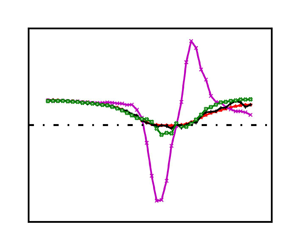
Figure 6 shows a remarkable similarity between the shapes of terms $\mathrm {II}$ and $\mathrm {III}$ on the right-hand side of the new momentum integral equation (2.9). Intriguingly, a better correlation in their shapes is observed when the $x$ axis is shifted. The origin of this shift is presently unclear. Nevertheless, figure 6 suggests that the magnitude of term $\mathrm {III}$ can be estimated as a fraction of term $\mathrm {II}$:

(3.3)\begin{equation} \int_0^{\delta_e} \frac{\partial R_{uu}}{\partial x} \mathrm{d}y \sim O \left(0.15 \left( \frac{1}{\rho}\frac{\mathrm{d} P_{wall}}{\mathrm{d}\kern0.06em x}+ U_e \frac{\mathrm{d}U_e}{\mathrm{d}\kern0.06em x}\right) \delta_e \right)\!. \end{equation}

Figure 6. Relation between term $\mathrm {III}$ and term $\mathrm {II}$ in the new momentum integral equation (2.9). The DNS data are from Coleman et al. (Reference Coleman, Rumsey and Spalart2018).

Thus, the wall shear stress can be estimated as

(3.4)\begin{equation} \frac{\tau_{wall}}{\rho} \sim \left(U_e \frac{\mathrm{d}U_e}{\mathrm{d}\kern0.06em x}\delta_1 + \frac{\mathrm{d}(U^2_e \delta_2)}{\mathrm{d}\kern0.06em x} \right) (1 + \beta_\kappa - c \beta_\kappa), \end{equation}

where $c$ is a factor of about $0.38$ for the DNS data of Coleman et al. (Reference Coleman, Rumsey and Spalart2018). For small $|\beta _\kappa | \lesssim 0.1$, the classical Kármán's integral provides accurate prediction of the wall shear stress, but its validity diminishes at larger values of $\beta _\kappa$.

4. Discussion

Turbulent boundary layer flows under pressure gradients, especially adverse ones, find extensive applications in aircraft, ships, wind turbines and various fluid systems. Understanding their behaviour is crucial, significantly influencing system performance and energy efficiency. Extensive research, theoretical, experimental and numerical (Rotta Reference Rotta1950; Clauser Reference Clauser1954; Townsend Reference Townsend1956; Stratford Reference Stratford1959; Mellor Reference Mellor1966; Mellor & Gibson Reference Mellor and Gibson1966; Skote, Henningson & Henkes Reference Skote, Henningson and Henkes1998; Castillo & George Reference Castillo and George2001; Bobke et al. Reference Bobke, Vinuesa, Örlü and Schlatter2017; Kitsios et al. Reference Kitsios, Sekimoto, Atkinson, Sillero, Borrell, Gungor, Jiménez and Soria2017; Coleman et al. Reference Coleman, Rumsey and Spalart2018; Maciel et al. Reference Maciel, Wei, Gungor and Simens2018; Devenport & Lowe Reference Devenport and Lowe2022; Subrahmanyam, Cantwell & Alonso Reference Subrahmanyam, Cantwell and Alonso2022), has focused on unravelling turbulent boundary layers under pressure gradients. Accurate determination of wall shear stress remains pivotal in this study.

Wall shear stress is a fundamental parameter in the analysis of wall-bounded flows. It serves to quantify the drag experienced by a surface and plays an essential role in the scaling and comprehension of flow dynamics. Several methods, as reviewed by Winter (Reference Winter1979), Haritonidis (Reference Haritonidis1989), Naughton & Sheplak (Reference Naughton and Sheplak2002) and Tavoularis (Reference Tavoularis2005), have been employed to directly measure or infer wall shear stress. However, obtaining an accurate determination of wall shear stress remains a challenge in practical applications.

The integral of the mean momentum equation offers a theoretical approach to indirectly determine wall shear stress (or friction coefficient $C_f = 2 \tau _{wall}/U^2_e$) given all pertinent terms are accurately measured. For example, Ligrani & Moffat (Reference Ligrani and Moffat1986) employed the momentum integral equation to determine wall shear stress on sand grain roughness by measuring mean streamwise velocity and Reynolds shear stress profiles at various $x$ stations. Brzek et al. (Reference Brzek, Cal, Johansson and Castillo2007) utilized closely spaced streamwise measurements of $\delta _2$ to determine wall shear stress in zero pressure gradient turbulent boundary layers. However, directly applying the momentum integral equation often involves streamwise gradient terms that are challenging to acquire with the necessary precision from experimental data.

Mehdi et al. (Reference Mehdi, Johansson, White and Naughton2014) developed an integral method based on the triple integration of the mean momentum equation. By replacing streamwise gradient terms with total stress gradient terms in the wall-normal direction, they determined $C_f$ using experimental data of mean velocity and Reynolds shear stress acquired at only one streamwise location. Given the inherent difficulty in measuring Reynolds shear stress very near the wall, they employed a fitting technique based on the expected shape of the total shear stress profile to smooth the experimental data and obtain the gradient.

More recently, Volino & Schultz (Reference Volino and Schultz2018) introduced an integral equation to determine wall shear stress without making assumptions about the shape of the mean velocity profile or relying on fitting experimental data to expected functions. Their approach involves transforming the integral equation into wall coordinates, separating terms dependent on streamwise gradients from those that are not. Although this method requires mean velocity and Reynolds shear stress profiles from at least two streamwise stations, it significantly diminishes reliance on streamwise gradients. Moreover, their methodology does not require data from very near the wall to determine wall shear stress. Their evaluation across diverse experimental and numerical datasets showcased the close agreement between the wall shear stress determined through their method and that obtained in the original studies.

In previous applications of the momentum integral for predicting wall shear stress, the advective terms in the $y$-momentum equation (2.4) were typically neglected, resulting in an approximation of the pressure as (see e.g. Rotta Reference Rotta1962)

(4.1)\begin{equation} \frac{P}{\rho} \approx \frac{P_{wall}}{\rho} + R_{vv}, \quad \mathrm{traditional\ analysis}. \end{equation}

At the boundary layer edge, where $R_{vv} \approx 0$, the pressure is approximated as $P_e \approx P_{wall}$. Moreover, in the conventional analysis, it is typically assumed that $-\partial (P/\rho )/\partial x|_e \approx U_e \,\mathrm {d}U_e/\mathrm{d}\kern0.06em x$. In essence, the second term $\mathrm {II}$ on the right-hand side of the new momentum integral equation (2.9) is assumed negligible in traditional analyses (Townsend Reference Townsend1956; Rotta Reference Rotta1962).

Figure 7 shows the second term $\mathrm {II}$ of (2.9) alongside its two components and the directly computed wall shear stress from the DNS data of Coleman et al. (Reference Coleman, Rumsey and Spalart2018). The figure indicates that when the pressure gradient is small, term $\mathrm {II}$ in (2.9) is negligible. However, in the presence of strong pressure gradients, term $\mathrm {II}$ becomes significant, greatly exceeding the magnitude of the wall shear stress. This highlights the crucial role of term $\mathrm {II}$ on the right-hand side of the new momentum integral equation (2.9) in predicting wall shear stress under strong adverse pressure gradients. Consequently, in experimental studies of turbulent boundary layers under such conditions, accurate measurement of wall pressure distribution is imperative and should not be approximated from $U_e(x)$ measurements.

Figure 7. Components of the second term $\mathrm {II}$ in (2.9) alongside the directly computed wall shear stress. The DNS data are from Coleman et al. (Reference Coleman, Rumsey and Spalart2018).

The new momentum integral equation (2.9) exhibits a close connection to the mean integral–momentum balance equation formulated by Coleman et al. (Reference Coleman, Rumsey and Spalart2018). However, our approach differs in two main aspects. Firstly, while Coleman et al. (Reference Coleman, Rumsey and Spalart2018) integrated the mean $x$-momentum equation along the $x$ direction, our derivation is conducted at a fixed $x$ location, akin to the conventional momentum integral analysis. Secondly, we leveraged the $y$-momentum equation to represent $P$ as a function of $P_{wall}$, $R_{vv}$, $V^2$ and $UV$ (refer to (2.5)), which further clarify the pressure variation's influence.

5. Summary

This study reveals the primary causes of the classical Kármán integral's failure in predicting wall shear stress accurately within turbulent boundary layers subjected to strong pressure gradients. Specifically, in the presence of strong adverse pressure gradients, the advective terms in the wall-normal momentum equation can significantly alter pressure distribution across the boundary layer. Consequently, the conventional approximation $-\partial (P/\rho )/\partial x \approx U_e \,\mathrm {d}U_e/\mathrm{d}\kern0.06em x$, typically employed in traditional analysis, becomes erroneous.

By incorporating the $y$-momentum equation's advective terms and retaining the often neglected Reynolds normal stress term in the $x$-momentum equation, we derive a more general momentum integral equation for wall shear stress calculation. Importantly, the classical Kármán's integral emerges as a special instance under minimal or zero pressure gradient conditions. The new momentum integral equation's predictive precision for wall shear stress within turbulent boundary layers is substantiated by its excellent agreement with DNS data. This agreement spans a wide range of pressure gradients, including even severe adverse pressure gradients that lead to flow separation. Additionally, the new momentum integral equation can be used to assess the quality of numerical simulations of turbulent boundary layers under strong pressure gradients.

Although the new momentum integral equation exhibits robust accuracy in predicting wall shear stress within turbulent boundary layers under arbitrary pressure gradients, its direct application in experimental practices faces challenges due to the difficulty and impracticality of accurately measuring $V$ and $R_{vv}$ in experiments. To address this, we introduce an empirical approximate equation for wall shear stress estimation, relying solely on easily measurable variables like $P_{wall}$, $U$ and $R_{uu}$. Despite the use of fewer data measurements, the resulting wall shear stress estimation demonstrates reasonable agreement with DNS data in turbulent boundary layers experiencing strong pressure gradients.

Furthermore, a novel dimensionless parameter, $\beta _\kappa$, is defined based on the new momentum integral equation to quantify the influence of pressure gradients on turbulent boundary layers. Our findings reveal that $\beta _\kappa$ remains close to zero in regions of weak pressure gradients but surpasses $O(1)$ in regions under strong pressure gradients. Consequently, the predictions of the classical Kármán's integral lose reliability in regions with a substantial magnitude of $\beta _\kappa$ – such as the $|\beta _\kappa | \gtrsim 0.1$ observed in this study.

Acknowledgements

We extend our gratitude to Dr Coleman for generously sharing the DNS data, accessible at https://turbmodels.larc.nasa.gov/Other_DNS_Data/separation_bubble_2d.html.

Declaration of interests

The authors report no conflict of interest.

Appendix A. Force distribution in the $y$-momentum equation

Figure 8 illustrates the contributions of various force terms in the mean $y$-momentum equation (2.3) at five different $x$ locations in the DNS of Coleman et al. (Reference Coleman, Rumsey and Spalart2018). Near the inlet ($x/Y=-10$) or near the simulation domain outlet ($x/Y=6$), where the pressure gradient is weak, the figure confirms the force balance between $-\partial (P/\rho )/\partial y$ and $\partial (R_{vv})/\partial y$, as assumed in the traditional integral analysis. However, at $x/Y=0$ or $x/Y=4$, where the pressure gradient is stronger, figure 8 shows that the advective force becomes increasingly important in maintaining the balance of the $y$-momentum equation, invalidating the approximate pressure equation (4.1) used in the traditional momentum integral analysis.

Figure 8. Distribution of the four forces in the $y$-momentum equation (2.3) at (ae) different $x$ stations: advective force ($F_{adv}$), viscous force ($F_{vis}$), turbulent force ($F_{tur}$) and pressure force ($F_{pre}$). Blue circles denote advective force, often overlooked in traditional analyses of turbulent boundary layer flows. The DNS data are from Coleman et al. (Reference Coleman, Rumsey and Spalart2018).

To further underscore the impact of advective terms in the balance of the $y$-momentum equation under pronounced pressure gradients, Figure 9 presents the variation of maximum force magnitudes along the $x$ direction. In regions with mild pressure gradients, such as near the inlet or outlet of the simulation domain of Coleman et al. (Reference Coleman, Rumsey and Spalart2018), the maximum magnitudes of turbulent and pressure forces dominate, while the advective force remains negligible. However, within the region spanning $-4 \lesssim x/Y \lesssim 4$, characterized by strong pressure gradients, the maximum magnitude of the advective force becomes comparable to those of the pressure and turbulent forces. This highlights the critical role of the advective force in accurately estimating the $y$-momentum equation under strong adverse pressure gradients, in contrast to the conventional analyses that often overlook its significance.

Figure 9. Variation of maximum magnitude of forces in the $y$-momentum equation. The DNS data are from Coleman et al. (Reference Coleman, Rumsey and Spalart2018).

Appendix B. Derivation of the momentum integral equation

The sum of the first two terms in (2.8) can be expressed as follows:

(B1)\begin{align} & - \int_0^{\delta_e} \frac{\partial U^2}{\partial x} \mathrm{d} y - U_eV_e \nonumber\\ &\quad =- \left(\frac{\mathrm{d} }{\mathrm{d}\kern0.06em x} \int_0^{\delta_e} U^2 \,\mathrm{d}y - U^2_e \frac{\mathrm{d} \delta_e}{\mathrm{d}\kern0.06em x} \right) -U_eV_e \nonumber\\ &\quad =- \left( \frac{\mathrm{d}}{\mathrm{d}\kern0.06em x}[U^2_e (\delta_e - \delta_1 - \delta_2) ] - U^2_e \frac{\mathrm{d} \delta_e}{\mathrm{d}\kern0.06em x} \right)- \left(-U_e \delta_e \frac{\mathrm{d}U_e}{\mathrm{d}\kern0.06em x} + U_e \frac{\mathrm{d}(U_e \delta_1)}{\mathrm{d}\kern0.06em x} \right) \nonumber\\ &\quad = U_e \frac{\mathrm{d}U_e}{\mathrm{d}\kern0.06em x} \delta_1 + \frac{\mathrm{d}(U^2_e \delta_2)}{\mathrm{d}\kern0.06em x} - U_e \frac{\mathrm{d}U_e}{\mathrm{d}\kern0.06em x}\delta_e. \end{align}

Note that by definition $\int _0^{\delta _e} U^2 \, \mathrm {d}y = U^2_e (\delta _e - \delta _1 - \delta _2)$. The mean wall-normal velocity at the boundary layer edge has been found to be $V_e=- {\delta _e} \,{\mathrm {d} U_e}/{\mathrm{d}\kern0.06em x} + {\mathrm {d} (U_e\delta _1)}/{\mathrm{d}\kern0.06em x}$ (see Wei et al. Reference Wei, Li, Knopp and Vinuesa2023).

The Leibniz integral rule can be applied to derive the following expressions:

(B2)\begin{align} \int_0^{\delta_e} \frac{\partial (R_{uu})}{\partial x} \mathrm{d}y & = \frac{\mathrm{d}}{\mathrm{d}\kern0.06em x} \int_0^{\delta_e} R_{uu} \,\mathrm{d}y - R_{uu}|_{y=\delta_e} \frac{\mathrm{d} \delta_e}{\mathrm{d}\kern0.06em x} \nonumber\\ & \approx \frac{\mathrm{d}}{\mathrm{d}\kern0.06em x} \int_0^{\delta_e} R_{uu} \,\mathrm{d}y, \end{align}
(B3)\begin{align} \int_0^{\delta_e} \frac{\partial (V^2 - R_{vv})}{\partial x} \mathrm{d}y &= \frac{\mathrm{d}}{\mathrm{d}\kern0.06em x} \int_0^{\delta_e} (V^2 - R_{vv})\, \mathrm{d}y - (V^2_e - R_{vv}|_{y=\delta_e}) \frac{\mathrm{d} \delta_e}{\mathrm{d}\kern0.06em x}, \end{align}
(B4)\begin{align} \int_0^{\delta_e} \frac{\partial }{\partial x} \left( \int_0^y \frac{\partial (UV)}{\partial x} \mathrm{d}y \right) \mathrm{d}y & = \frac{\mathrm{d}}{\mathrm{d}\kern0.06em x} \int_0^{\delta_e} \left(\int_0^y \frac{\partial (UV)}{\partial x} \mathrm{d}y \right) \mathrm{d}y - \frac{\mathrm{d} \delta_e}{\mathrm{d}\kern0.06em x} \int_0^{\delta_e} \frac{\partial (UV)}{\partial x} \mathrm{d}y \nonumber\\ & =\frac{\mathrm{d}}{\mathrm{d}\kern0.06em x} \int_0^{\delta_e} \left(\int_0^y \frac{\partial (UV)}{\partial x} \mathrm{d}y \right) \mathrm{d}y \nonumber\\ & \quad -\frac{\mathrm{d} \delta_e}{\mathrm{d}\kern0.06em x} \left\{ \frac{\mathrm{d}}{\mathrm{d}\kern0.06em x} \int_0^{\delta_e} (UV)\,\mathrm{d}y - (U_e V_e) \frac{\mathrm{d} \delta_e}{\mathrm{d}\kern0.06em x} \right\} . \end{align}

Appendix C. Estimations of the terms III, IV and V in (2.9)

For a zero pressure gradient turbulent boundary layer, it is generally agreed that Reynolds normal stresses like $R_{uu}$ and $R_{vv}$ scale with the friction velocity (see e.g. Pope Reference Pope2000). Moreover, the mean wall-normal velocity at the boundary layer edge can be approximated as $V_e \approx u_\tau (u_\tau /U_e) H_{12}$, where $H_{12}=\delta _1/\delta _2$ is the shape factor (Wei & Klewicki Reference Wei and Klewicki2016Reference Wei and Klewicki2023). Therefore, a rough estimation of the order of magnitudes for terms III and IV can be expressed as

(C1)$$\begin{gather} \int_0^{\delta_e} \frac{\partial R_{uu}}{\partial x} {{\rm d}y} \sim O\left(u^2_\tau \frac{\delta_e}{L_x} \right) \ll u^2_\tau, \end{gather}$$
(C2)$$\begin{gather}\int_0^{\delta_e} \frac{\partial (V^2 - R_{vv})}{\partial x} {{\rm d}y} \sim O\left(u^2_\tau \left(\frac{u_\tau}{U_e}\right)^2 \frac{\delta_e}{L_x}\right) - O\left(u^2_\tau \frac{\delta_e}{L_x} \right) \ll u^2_\tau, \end{gather}$$

where $L_x$ is a characteristic length scale in the streamwise direction, much larger than the boundary layer thickness in a zero pressure gradient turbulent boundary layer. Moreover, it can be shown that the term $\partial (UV)/\partial x \sim O(H_{12}\, u^2_\tau /L_x)$, which is smaller than the term $\partial R_{vv}/\partial y$ in (2.4). Consequently, terms $\mathrm {III}$, $\mathrm {IV}$ and $\mathrm {V}$ in (2.9) would be negligible for turbulent boundary layer under zero or mild pressure gradients. This estimation is substantiated in figure 2, where it is evident that terms $\mathrm {III}$, $\mathrm {IV}$ and $\mathrm {V}$ exhibit similar orders of magnitude and are significantly smaller than the wall shear stress in regions under small pressure gradients.

In experimental studies, calculating terms $\mathrm {II}$, $\mathrm {III}$ and $\mathrm {IV}$ in (2.9) from measurements is nearly impossible due to limited data in the $x$ direction. To assess the effects of pressure gradients on these terms, one can use the variation of the integrals $\int _0^{\delta _e}R_{uu}\,{{\rm d}y}$, $\int _0^{\delta _e}R_{vv}\,{{\rm d}y}$ and $\int _0^{\delta _e}V^2\,{{\rm d}y}$ in the $x$ direction to estimate the magnitudes of their derivatives. For instance, figure 10, using DNS data, shows the pressure difference between the edge and wall, along with the integrals $\int _0^{\delta _e}R_{uu}\,{{\rm d}y}$, $\int _0^{\delta _e}R_{vv}\,{{\rm d}y}$ and $\int _0^{\delta _e}V^2\, {{\rm d}y}$ plotted against streamwise locations $x$. For dimensional comparison, the pressure difference is multiplied by $\delta _e$. The figure confirms that, in regions characterized by mild pressure gradients, $R_{uu}$ and $R_{vv}$ demonstrate similar magnitudes, while the integral of $V^2$ is notably smaller (see (C2)). Under strong pressure gradients, either adverse or favourable, figure 10 displays similar orders of magnitudes for the integrals of $R_{uu}$, $R_{vv}$ and $V^2$, which are smaller than the pressure difference term. Moreover, these terms, in general, exhibit more gradual variations in the $x$ direction compared with the pressure term's variability. This tendency is consistent with the comparable magnitudes of terms $\mathrm {III}$ and $\mathrm {IV}$, both of which are smaller than the magnitude of term $\mathrm {II}$, as illustrated in figure 2.

Figure 10. The pressure difference between the edge and wall, along with the integrals of $R_{uu}$, $R_{vv}$ and $V^2$. The DNS data are from Coleman et al. (Reference Coleman, Rumsey and Spalart2018).

Examining (2.4), it is evident that term $\mathrm {V}$ in the new momentum integral equation (2.9) originates from a portion of the advective terms in the $y$-momentum equation. It is reasonable to estimate its magnitude to be comparable to that from $\partial V^2/\partial y$. Hence, the magnitude of term $\mathrm {V}$ is expected to be similar to that of term $\mathrm {IV}$, as shown in figure 2.

References

Bobke, A., Vinuesa, R., Örlü, R. & Schlatter, P. 2017 History effects and near equilibrium in adverse-pressure-gradient turbulent boundary layers. J. Fluid Mech. 820, 667692.CrossRefGoogle Scholar
Brzek, B., Cal, R.B., Johansson, G. & Castillo, L. 2007 Inner and outer scalings in rough surface zero pressure gradient turbulent boundary layers. Phys. Fluids 19 (6), 065101.CrossRefGoogle Scholar
Castillo, L. & George, W.K. 2001 Similarity analysis for turbulent boundary layer with pressure gradient: outer flow. AIAA J. 39 (1), 4147.CrossRefGoogle Scholar
Clauser, F.H. 1954 Turbulent boundary layers in adverse pressure gradients. J. Aeronaut. Sci. 21, 91108.CrossRefGoogle Scholar
Coleman, G.N., Rumsey, C.L. & Spalart, P.R. 2018 Numerical study of turbulent separation bubbles with varying pressure gradient and Reynolds number. J. Fluid Mech. 847, 2870.CrossRefGoogle ScholarPubMed
Devenport, W.J. & Lowe, K.T. 2022 Equilibrium and non-equilibrium turbulent boundary layers. Prog. Aerosp. Sci. 131, 100807.CrossRefGoogle Scholar
Gruschwitz, E. 1931 Die turbulente Reibungsschicht in ebener Strömung bei Druckabfall und Druckanstiegs. Springer.CrossRefGoogle Scholar
Haritonidis, J.H. 1989 The measurement of wall shear stress. In Advances in Fluid Mechanics Measurements (ed. M. Gad-el-Hak), pp. 229–261. Springer.CrossRefGoogle Scholar
von Kármán, Th.V. 1921 Über laminare und turbulente reibung. Z. Angew. Math. Mech. 1 (4), 233252.CrossRefGoogle Scholar
Kitsios, V., Sekimoto, A., Atkinson, C., Sillero, J.A., Borrell, G., Gungor, A.G., Jiménez, J. & Soria, J. 2017 Direct numerical simulation of a self-similar adverse pressure gradient turbulent boundary layer at the verge of separation. J. Fluid Mech. 829, 392419.CrossRefGoogle Scholar
Kundu, P.K., Cohen, I.M. & Dowling, D.R. 2012 Fluid Mechanics. Academic.Google Scholar
Ligrani, P.M. & Moffat, R.J. 1986 Structure of transitionally rough and fully rough turbulent boundary layers. J. Fluid Mech. 162, 6998.CrossRefGoogle Scholar
Maciel, Y., Wei, T., Gungor, A.G. & Simens, M.P. 2018 Outer scales and parameters of adverse-pressure-gradient turbulent boundary layers. J. Fluid Mech. 844, 535.CrossRefGoogle Scholar
Mehdi, F., Johansson, T.G., White, C.M. & Naughton, J.W. 2014 On determining wall shear stress in spatially developing two-dimensional wall-bounded flows. Exp. Fluids 55, 19.CrossRefGoogle Scholar
Mellor, G.L. 1966 The effects of pressure gradients on turbulent flow near a smooth wall. J. Fluid Mech. 24 (2), 255274.CrossRefGoogle Scholar
Mellor, G.L. & Gibson, D.M. 1966 Equilibrium turbulent boundary layers. J. Fluid Mech. 24 (2), 225253.CrossRefGoogle Scholar
Naughton, J.W. & Sheplak, M. 2002 Modern developments in shear-stress measurement. Prog. Aerosp. Sci. 38 (6–7), 515570.CrossRefGoogle Scholar
Pohlhausen, K. 1921 Zur näherungsweisen integration der differentialgleichung der iaminaren grenzschicht. Z. Angew. Math. Mech. 1 (4), 252290.CrossRefGoogle Scholar
Pope, S.B. 2000 Turbulent Flows. Cambridge University Press.CrossRefGoogle Scholar
Rotta, J. 1950 Über die Theorie turbulenter Grenzschichten. Tech. Rep. NACA-TM-1344. Mitteilungen aus dem Max-Planck-Institut für Strömungsforschung Nr. 1. (Translated as: On the theory of turbulent boundary layers. NACA Technical Memorandum No. 1344, 1953.).Google Scholar
Rotta, J.C. 1962 Turbulent boundary layers in incompressible flow. Prog. Aerosp. Sci. 2 (1), 195.CrossRefGoogle Scholar
Schlichting, H. 1979 Boundary-Layer Theory. McGraw-Hill.Google Scholar
Skote, M., Henningson, D.S. & Henkes, R.A.W.M. 1998 Direct numerical simulation of self-similar turbulent boundary layers in adverse pressure gradients. Flow Turbul. Combust. 60 (1), 4785.CrossRefGoogle Scholar
Stratford, B.S. 1959 The prediction of separation of the turbulent boundary layer. J. Fluid Mech. 5 (1), 116.CrossRefGoogle Scholar
Subrahmanyam, M.A., Cantwell, B.J. & Alonso, J.J. 2022 A universal velocity profile for turbulent wall flows including adverse pressure gradient boundary layers. J. Fluid Mech. 933, A16.CrossRefGoogle Scholar
Tavoularis, S. 2005 Measurement in Fluid Mechanics. Cambridge University Press.Google Scholar
Tennekes, H. & Lumley, J.L. 1972 A First Course in Turbulence. MIT.CrossRefGoogle Scholar
Townsend, A.A. 1956 The Structure of Turbulent Shear Flow. Cambridge University Press.Google Scholar
Volino, R.J. & Schultz, M.P. 2018 Determination of wall shear stress from mean velocity and Reynolds shear stress profiles. Phys. Rev. Fluids 3 (3), 034606.CrossRefGoogle Scholar
Wei, T. & Klewicki, J. 2016 Scaling properties of the mean wall-normal velocity in zero-pressure-gradient boundary layers. Phys. Rev. Fluids 1 (8), 082401.CrossRefGoogle Scholar
Wei, T. & Klewicki, J. 2023 Integral relation in zero-pressure-gradient boundary layer flows. Phys. Rev. Fluids 8, 124601.CrossRefGoogle Scholar
Wei, T., Li, Z., Knopp, T. & Vinuesa, R. 2023 The mean wall-normal velocity in turbulent-boundary-layer flows under pressure gradient. J. Fluid Mech. 975, A27.CrossRefGoogle Scholar
Winter, K.G. 1979 An outline of the techniques available for the measurement of skin friction in turbulent boundary layers. Prog. Aerosp. Sci. 18, 157.CrossRefGoogle Scholar
Figure 0

Figure 1. (a) Comparison between Kármán's integral and the directly computed wall shear stress from the DNS data of Coleman et al. (2018). (b) Variation of the Rotta–Clauser pressure gradient parameter along the $x$ direction. Vertical dashed lines indicate $x$ positions with $|\beta _{RC}|=10$. The larger $\beta _{RC}$ values around the separation region are shown in figure 3. The streamwise location is normalized by the simulation domain height in the wall-normal direction, denoted as $Y$.

Figure 1

Figure 2. Comparison of terms in the new momentum integral equation (2.9) and their summation with the directly computed wall shear stress. The DNS data are from Coleman et al. (2018), displaying every 50th grid point in the $x$ direction for clarity.

Figure 2

Figure 3. Newly defined pressure parameter $\beta _\kappa$ and the conventional $\beta _{RC}$. The DNS data are from Coleman et al. (2018).

Figure 3

Figure 4. Approximation of the sum of terms $\mathrm {IV}$ and $\mathrm {V}$ in (2.9). The DNS data are from Coleman et al. (2018).

Figure 4

Figure 5. Comparison of directly calculated wall shear stress with predictions from the Kármán integral equation (1.1), the new momentum integral equation (2.9) and the approximate equation (3.2). The DNS data are from Coleman et al. (2018).

Figure 5

Figure 6. Relation between term $\mathrm {III}$ and term $\mathrm {II}$ in the new momentum integral equation (2.9). The DNS data are from Coleman et al. (2018).

Figure 6

Figure 7. Components of the second term $\mathrm {II}$ in (2.9) alongside the directly computed wall shear stress. The DNS data are from Coleman et al. (2018).

Figure 7

Figure 8. Distribution of the four forces in the $y$-momentum equation (2.3) at (ae) different $x$ stations: advective force ($F_{adv}$), viscous force ($F_{vis}$), turbulent force ($F_{tur}$) and pressure force ($F_{pre}$). Blue circles denote advective force, often overlooked in traditional analyses of turbulent boundary layer flows. The DNS data are from Coleman et al. (2018).

Figure 8

Figure 9. Variation of maximum magnitude of forces in the $y$-momentum equation. The DNS data are from Coleman et al. (2018).

Figure 9

Figure 10. The pressure difference between the edge and wall, along with the integrals of $R_{uu}$, $R_{vv}$ and $V^2$. The DNS data are from Coleman et al. (2018).