


1. Introduction
Electromagnetic radiation with a frequency ranging from $0.3$ to $10\times 10^{12}$
 Hz refers to terahertz (THz) gap (Shumyatsky & Alfano Reference Shumyatsky and Alfano2011). Recently, THz has attracted a lot of interest because its frequency application can be used in spectroscopy (Afsah-Hejri et al. Reference Afsah-Hejri, Hajeb, Ara and Ehsani2019; Spies et al. Reference Spies, Neu, Tayvah, Capobianco, Pattengale, Ostresh and Schmuttenmaer2020), communication (Yang et al. Reference Yang, Yamagami, Yu, Pitchappa, Webber, Zhang, Fujita, Nagatsuma and Singh2020; Ghazialsharif et al. Reference Ghazialsharif, Dong, Abbes and Morandotti2023; Katyba et al. Reference Katyba, Raginov, Khabushev, Zhelnov, Gorodetsky, Ghazaryan, Mironov, Krasnikov, Gladush and Lloyd-Hughes2023), imaging in medical diagnostics (Peng et al. Reference Peng, Shi, Wu, Zhu and Zhuang2020; Zhang et al. Reference Zhang, Wang, Huai, Wang, Zhang, Wang, Rong and Zheng2020; Wang Reference Wang2021), sensing (Islam et al. Reference Islam, Bhowmik, Dhriti, Mohan, Ahmad and Kumar2022; Lai et al. Reference Lai, Li, Fu and Lin2023; Tan et al. Reference Tan, Guo, Shu and Xu2023), detection (Lewis Reference Lewis2019), etc. Terahertz radiation can be generated by a variety of techniques and processes, such as laser–plasma interaction (Malik & Singh Reference Malik and Singh2020; Manendra et al. Reference Manendra, Singh, Bhati and Malik2020), electron beam–plasma interaction (Yang et al. Reference Yang, Wang, Wang, Zhang, Xia, Tang and Gong2022; Gupta, Gurjar & Jain Reference Gupta, Gurjar and Jain2023), photoconductivity antenna (Isgandarov et al. Reference Isgandarov, Ropagnol, Singh and Ozaki2021; Lu et al. Reference Lu, Jiang, Zhao, Turan and Jarrahi2022; Sandeep & Malik Reference Sandeep and Malik2023), electron beam or laser interaction with a semiconductor or metal (Liu et al. Reference Liu, Kumar, Singh and Tripathi2007; Davidson et al. Reference Davidson, Petrov, Rock, Grugan, Gordon, Hafizi, Ting and Peñano2020; Dong et al. Reference Dong, Li, Manjappa, Yang, Zhou, Kong, Quan, Chen, Ouyang and Dai2021), nonlinear mixing of lasers (Kumar, Rajouria & KK Reference Kumar, Rajouria and KK2013; Kumar et al. Reference Kumar, Lee, Hee Park, Uk Jeong and Vinokurov2017, Reference Kumar, Song, Lee, Park, Suk and Hur2023; Srivastav & Panwar Reference Srivastav and Panwar2022), optical rectification (Lee et al. Reference Lee, Meade, Perlin, Winful, Norris and Galvanauskas2000; Yeh et al. Reference Yeh, Hoffmann, Hebling and Nelson2007; Aoki, Savolainen & Havenith Reference Aoki, Savolainen and Havenith2017) and second and third harmonic generation (Beer et al. Reference Beer, Gour, Alberucci, David, Nolte and Zeitner2022; Gour et al. Reference Gour, Beer, Alberucci, Zeitner and Nolte2022) etc. Kumar et al. (Reference Kumar, Kang, Kylychbekov, Song and Hur2021) investigated THz radiation generation by beating of two laser pulses of finite spot size in a rippled density plasma. Kumar et al. (Reference Kumar, Kang, Kylychbekov, Song and Hur2021) studied excitation of THz radiation by nonlinear mixing of two continuous wave-laser beams in an axially modulated magnetized plasma. Jang et al. (Reference Jang, Sung, Lee, Kang and Kim2020) observed experimentally the excitation of multicycle and narrowband THz radiation by optical rectification of femtosecond laser pulses in $\text {LiNbO}_{3}$
 crystal. Voevodin et al. (Reference Voevodin, Bereznaya, Sarkisov, Yudin and Sarkisov2022) experimentally demonstrated THz generation by optical rectification of 780 nm femtosecond laser pulses on $\text {ZnGeP}_{2}$
 and $\text {ZnGeP}_{2}:\text {Sc}$
 crystals and reported that the $\text {ZnGeP}_{2}:\text {Sc}$
 crystal was more efficient for optical rectification. Wang et al. (Reference Wang, Qiu, Jin, Ge, Shen, Hu, Li, Nakajima, Jin and Lu2022) observed THz radiation generation by optical rectification from a liquid crystal using an 800 nm femtosecond laser and reported that the polarization of the femtosecond laser and the liquid crystal's orientation affected the THz amplitude. Kumar, Singh & Sharma (Reference Kumar, Singh and Sharma2016b) reported strong THz radiation generation by optical rectification of a super-Gaussian laser beam in rippled plasma. Singh et al. (Reference Singh, Singh, Rajouria and Sharma2017a) discussed the generation of THz radiation from a shaped laser pulse by optical rectification in rippled plasma with an axial magnetic field. Singh et al. (Reference Singh, Singh, Rajouria and Sharma2017b) examined the strong THz radiation generation of hyperbolic-secant laser pulses by optical rectification in magnetized (transversely) rippled plasma. Bhasin & Tripathi (Reference Bhasin and Tripathi2009) theoretically investigated the THz radiation generation of an x-mode laser in magnetized rippled plasma by optical rectification. Bhasin & Tripathi (Reference Bhasin and Tripathi2010) reported the resonant excitation of THz surface plasma waves (SPWs) by optical rectification of the SPW modulated amplitude on a rippled metal surface.
The electron density in metals is of the order of ${\approx }10^{28}\,\text {m}^{-3}$ and the corresponding plasma frequency is $10^{15}$
 Hz, which lies in the visible region (Deepika et al. Reference Deepika, Chauhan, Varshney, Singh and Sajal2015; Sharma, Ghotra & Kant Reference Sharma, Ghotra and Kant2018). In a semiconductor (n-type), the electron density is ${\approx }10^{23}\,\text {m}^{-3}$
 and the relative plasma frequency is of the order of $10^{12}$
 Hz, which lies in THz region (Kumar, Kumar & Tripathi Reference Kumar, Kumar and Tripathi2016a; Gupta Reference Gupta2021; Srivastav & Panwar Reference Srivastav and Panwar2023). The plasma frequency and dispersion relation of SPWs can be tuned with temperature and an external magnetic field, respectively. Srivastav & Panwar (Reference Srivastav and Panwar2023) explored the effect of a magnetic field over the excitation of a THz surface magnetoplasmon (SMP) wave on n-type indium antimonide (n-InSb) by beating the laser and its second harmonic frequencies.
In the present paper, we investigated the excitation of THz SMPs by optical rectification of the modulated amplitude of the SMP wave on a rippled surface of a semiconductor (n-InSb) in the presence of an external magnetic field (see figure 1). The excitation of the SMPs can be achieved by an amplitude modulated laser (p-polarized) obliquely incident at an angle on the interface between a semiconductor and free space. This can be achieved in either the attenuated total reflection configuration or by directly impinging the laser on a semiconductor surface with a ripple of specific wavenumber $q$ , where $q$
 is the difference between the SMPs’ wavenumber and the component of the laser wave vector along the semiconductor surface. A modulated amplitude of the SMP wave exerts a ponderomotive force on the free electrons of the semiconductor (n-InSb). The ponderomotive force imparts an oscillatory velocity to the free electrons at the modulation frequency. This oscillatory velocity couples with the modulated electron density to produce a nonlinear current density at the modulation frequency, and resonantly excites the THz SMP wave at the modulation frequency. In Sec.II, we discussed the temperature-dependent dispersion relation of THz SMPs. Sec.III represents the linear response of THz SMPs at the modulation frequency. Sec.IV represents the excitation process of the THz SMP field. Results and discussion are in Sec.V and the conclusion in Sec.VI.

Figure 1. Schematic of linear mode conversion of an amplitude modulated laser into a SMP wave and the excitation of THz SMP radiation by the latter at the modulation frequency.
2. Temperature-dependent dispersion relation of terahertz surface magnetoplasmon
Assume that $x=0$ represents the interface between a rippled semiconductor (n-type) ($x\leq 0$
 ) and free space ($x>0$
 ) with the electron density perturbation $n = (n_0/2)(1+\cos q z)$
 (Srivastav & Panwar Reference Srivastav and Panwar2023), where $q a\geq 1$
 , $a$
, $a$ and $q$
 are the amplitude and ripple wavenumber, respectively. Apply the magnetic field $B_{0}\hat {y}$
 to the semiconductor (n-type) (cf. figure 1). The effective mass $m_{e}^{\ast }$
 of free electrons inside a semiconductor (n-type) is $0.014 m_{e}$
 . The effective permittivities $\overline {\bar {\epsilon }}$
 of the semiconductor (n-type) components are presented by $\varepsilon _{{\rm eff}} = (\epsilon _{x x}^{2} + \epsilon _{x z}^{2})/ (\epsilon _{x x})$
 , $\epsilon _{x x} = \epsilon _{z z} = \epsilon _r-(\epsilon _r{\omega _{p}^2 (\omega + {\rm i}\nu )})/\omega ((\omega + {\rm i}\nu )^2 - \omega ^2_{{\rm ce}})$
 , $\epsilon _{x z} =-\epsilon _{ z x} =-{\rm i} {\epsilon _r \omega _{{\rm ce}}\omega _{p}^2}/\omega ((\omega + {\rm i}\nu )^2 - \omega ^2_{{\rm ce}})$
 , $\omega _{{\rm ce}} = e B_{0}/m_{e}^{\ast }$
 is the electron cyclotron frequency, e is electron charge, $\omega _{p}=\sqrt {(n_{0} e^{2})/(m_{e}^{\ast } \epsilon _{0}\epsilon _{r})}$
 is the electron plasma frequency, $\nu$
 is the collision frequency of electrons and the temperature-dependent electron density $n_{0}= 5.76\times 10^{20}\,\text {T}^{3/2}\exp (-0.26/2\text {k}_{\text {B}}\text {T})$
 of n-InSb (Srivastav & Panwar Reference Srivastav and Panwar2023), where $\text {k}_{\text {B}}$
 and $\text {T}$
 are the Boltzmann constant and temperature, respectively.
The electric field of the SMP wave is given as

where $A=A_{0}(1+\mu \cos \varOmega (t-z/v_{g}))$ , $\beta _{1} = -({\rm i} k_{z}/ \alpha _{1})$
 , $\beta _{2} = ( {\epsilon _{x z} \alpha _{2}+ \epsilon _{x x} {\rm i} k_{z}}) /( -\epsilon _{x x} \alpha _{2} + \epsilon _{x z} {\rm i} k_{z} )$
 , $\alpha _{2}^2 = k_z^2 -(\omega ^2/c^2) (({\epsilon ^2_{x z} + \epsilon ^2_{x x}})/{\epsilon _{x x}})$
 , $\alpha _{1}^2 = k_z^2 -(\omega ^2/c^2)$
 , $\epsilon _{{\rm eff}} = ({\epsilon ^2_{x z} + \epsilon ^2_{x x}})/{\epsilon _{x x}}$
 and $v_{g}$
 is the group velocity of the SMP wave.
It adheres to the dispersion relation (Srivastav & Panwar Reference Srivastav and Panwar2023) as

Srivastav & Panwar (Reference Srivastav and Panwar2022, Reference Srivastav and Panwar2023) reported the dispersion curve of SMPs for different values of the normalized electron cyclotron frequency $\omega _{{\rm ce}}/\omega _{p}$ . It shows that the dispersion curve of SMPs shifts away from the dispersion curve of electromagnetic waves in free space for increases in the normalized electron cyclotron frequency.
The dispersion curve of SMPs and electromagnetic waves is shown in figure 2 for different semiconductor temperatures $T=310$ K (orange dot dashed line), $T=300$
 K (magenta dotted line), $T=290$
 K (red dashed line) and $T=280$
 K (green double dot dashed line) at the normalized electron cyclotron frequency $\omega _{{\rm ce}}/\omega _{p} = 0.05$
 . Dispersion curve of SMPs shifts towards a lower normalized THz frequency as the semiconductor (n-InSb) temperature increases. The cutoff frequency of the dispersion curve also shifts to a lower normalized THz frequency with increases in the semiconductor's temperature.

Figure 2. The $\omega /\omega _{p}$ variation with $k_{z}c/\omega _{p}$
 for temperature $T=310$
 K (orange dot dashed line), $T=300$
 K (magenta dotted line), $T=290$
 K (red dashed line) and $T=280$
 K (green double dot dashed line) at normalized electron cyclotron frequency $\omega _{{\rm ce}}/\omega _{p} = 0.05$
 .
.
3. Linear response of terahertz surface magnetoplasmons
The SMP wave imparts a linear oscillatory velocity to the free electrons of the semiconductors as

and

where $\tilde {v}_{\omega }^x = ( \omega _{{\rm ce}} - {\rm i} (\omega + {\rm i} \nu ) {\beta _2} ) / ((\omega + {\rm i} \nu )^2 - \omega _{{\rm ce}}^2)$ and $\tilde {v}_{\omega }^z = - ( \omega _{{\rm ce}} {\beta _2} + {\rm i} (\omega + {\rm i} \nu ) ) / ((\omega + {\rm i} \nu )^2 - \omega _{{\rm ce}}^2)$
 .
.
The SMP wave exerts a ponderomotive force $\boldsymbol {F}_p = - (m_e^{\ast }/4) (\boldsymbol {v}_s \boldsymbol {\cdot } \boldsymbol {\nabla } \boldsymbol {v}_s^{\ast } + \boldsymbol {v}_s^{\ast } \boldsymbol {\cdot } \boldsymbol {\nabla } \boldsymbol {v}_s) - (e/4) (\boldsymbol {v}_s \times \boldsymbol {B}_s^{\ast } + \boldsymbol {v}_s^{\ast } \times \boldsymbol {B}_s)$ on the free electrons and it is represented as

where

and

The ponderomotive force at modulation frequency $\varOmega$ can be written as

Now, the oscillatory velocity components of the free electrons at modulation frequency $\varOmega$ are given as

and

where $\tilde {v}_{\varOmega }^x = ({\rm i} (\varOmega + {\rm i} \nu ) F_{P x}) / ((\varOmega + {\rm i} \nu )^2 - \omega _{{\rm ce}}^2)$ and $\tilde {v}_{\varOmega }^z = (\omega _{{\rm ce}} F_{P x}) / ((\varOmega + {\rm i} \nu )^2 - \omega _{{\rm ce}}^2)$
 .
.
The oscillatory velocity couples with the modulated electron density to produce current density $\boldsymbol {J}_{\varOmega }$ at modulation frequency $\varOmega$
 and it is given as

4. Excitation process of terahertz surface magnetoplasmon field
By using Maxwell's equation, the $\varOmega$ modulation frequency SMP wave field can be expressed as

and

where $\varepsilon _{{\rm eff}}^{\varOmega } = ((\epsilon _{x x}^{\varOmega })^{2} + (\epsilon _{x z}^{\varOmega })^{2})/ (\epsilon _{x x}^{\varOmega })$ , $\epsilon _{x x}^{\varOmega } = \epsilon _{z z}^{\varOmega } = \epsilon _r-(\epsilon _r{\omega _{p}^2 (\varOmega + {\rm i} \nu )})/\varOmega ( (\varOmega + {\rm i}\nu )^2 - \omega ^2_{{\rm ce}} )$
 , $\epsilon _{ x z}^{\varOmega } =-\epsilon _{ z x}^{\varOmega } =-{\rm i} {\epsilon _r \omega _{{\rm ce}}\omega _{p}^2}/\varOmega ((\varOmega + {\rm i}\nu )^2 - \omega ^2_{{\rm ce}}) \text { for}\ x \leq 0$
 and $\varepsilon _{{\rm eff}}^{\varOmega } = 1 \text { for}\ x > 0$
 , and $s$
 represents the SMPs.
The wave equation may be written as

Here, $\overline {\bar {\epsilon }}$ is an n-type semiconductor effective permittivity at frequency $\varOmega$
 . When the right-hand side term of (4.2) is zero, that is $\boldsymbol {J}_{\varOmega }$
 is absent, then the SMP eigenmode structure with

where $\boldsymbol {E}_{s,0}$ and $\boldsymbol {B}_{s,0}$
 is given as

and

The SMP electric field can be represented as

where $\beta _{1}^{\varOmega } \!=\! -({\rm i} k_{z}^{\varOmega }/ \alpha _{1}^{\varOmega })$ , $\beta _{2}^{\varOmega } \!=\! ( {\epsilon _{x z}^{\varOmega } \alpha _{2}^{\varOmega }+ \epsilon _{x x}^{\varOmega } {\rm i} k_{z}^{\varOmega }})/({ -\epsilon _{x x}^{\varOmega } \alpha _{2}^{\varOmega } + \epsilon _{x z}^{\varOmega } {\rm i} k_{z}^{\varOmega } })$
 , $(\alpha _{2}k_z^{\varOmega })^2 = (k_z^{\varOmega })^2 -(\varOmega ^2/c^2) \epsilon _{{\rm eff}}^{\varOmega }$
 , $(\alpha _{1}^{\varOmega })^2 = (k_z^{\varOmega })^2 -(\varOmega ^2/c^2)$
 , $k_{z}^{\varOmega } = q + \varOmega /v_{g}$
 and $q$
 provides the extra wave-number for the phase matching condition.
Figure 3 represents the variation of normalized ripple wavenumber $qc/\omega _{p}$ with normalized electron cyclotron frequency $\omega _{{\rm ce}}/\omega _{p}$
 for the three values of THz frequency $\omega = 0.5$
 THz (green line), $\omega = 1.0$
 THz (blue dashed line) and $\omega = 1.5$
 THz (red dot dashed line). Normalized ripple wavenumber $qc/\omega _{p}$
 increases with an increase in the normalized electron cyclotron frequency $\omega _{{\rm ce}}/\omega _{p}$
 at $\omega _{p} = 2.7$
 THz. Also, it increases with a decrease in the THz frequency.

Figure 3. Variation of normalized ripple wavenumber $q$ with normalized electron cyclotron frequency $\omega _{{\rm ce}}/\omega _{p}$
 for THz frequency $\omega = 0.5$
 THz (green line), $\omega = 1.0$
 THz (blue dashed line) and $\omega = 1.5$
 THz (red dot dashed line).
If the current density $\boldsymbol {J}_{\varOmega }$ is present, then the electric and magnetic fields of the THz SMP wave can be expressed as

Solving (4.1) and (4.2) with (4.8a,b), and using (4.4), we get

and

Using (4.10) in (4.9) and taking $\partial a /\partial t \approx \partial b /\partial t$ , we get

Multiplying (4.11) by $\boldsymbol {E}_{s,0}^{\ast }\,{{\rm d}x}$ and integrating $- \infty$
 to $\infty$
 , we obtain

where $I_{1} = \int ^{\infty }_{- \infty } \boldsymbol {E}_{s,0} \boldsymbol {\cdot } \boldsymbol {E}_{s,0}^{\ast }\,{{\rm d}x}$ and $I_{2} = \int ^{\infty }_{- \infty } \boldsymbol {J}_{\varOmega } \boldsymbol {\cdot } \boldsymbol {E}_{s,0}^{\ast }\,{{\rm d}x}$
 .
.
Solving the (4.12), one may obtain

Letting $\partial /\partial t = - {\rm i} \varOmega$ , we obtain

The amplitude ratio of THz SMPs to the SMP pump ($a/A_{0}$ ) is represented by (4.14). It shows that $a/A_{0}$
 is directly proportional to the amplitude $A_{0}$
 and modulation index $\mu$
 of the SMP wave. The amplitude ratio of THz SMPs ($a/A_{0}$
 ) also depends upon the electron cyclotron frequency $\omega _{{\rm ce}}$
 (external magnetic field $B_{0} \hat {y}$
 ) and n-type semiconductor temperature. The following parameter modulation index $\mu = 0.3$
 , ripple height ${h} = 50\,\mathrm {\mu }$
 m, effective mass of free electrons $m_{e}^{\ast } = 0.014 m_{e}$
 , $\epsilon _{r} = 15.68$
 are used for the numerical study of the THz SMP wave.
5. Results and discussion
The amplitude ratio of THz SMP ($a/A_{0}$ ) variation with normalized THz frequency $\omega /\omega _{p}$
 is plotted in figure 4 for normalized electron cyclotron frequency $\omega _{{\rm ce}}/\omega _{p} = 0$
 (green line), $\omega _{{\rm ce}}/\omega _{p} = 0.05$
 (red dashed line), $\omega _{{\rm ce}}/\omega _{p} = 0.1$
 (blue dot-dashed line) and $\omega _{{\rm ce}}/\omega _{p} = 0.15$
 (yellow dotted line) at $\mu = 0.3$
 , $n_{0} = 1.96 \times 10^{22}\,\text {m}^{-3}$
 , $\epsilon _{r} = 15.68$
 and ripple height ${h} = 50\,\mathrm {\mu }$
 m. The amplitude ratio of THz SMPs increases with an increase in normalized electron cyclotron frequency $\omega _{{\rm ce}}/\omega$
 and decreases with normalized THz frequency $\omega /\omega _{p}$
 . Figure 5 represents the variation of the amplitude ratio of THz SMPs ($a/A_{0}$
 ) with normalized THz frequency $\omega /\omega _{p}$
 for temperature $T = 280\,\text {K}$
 (yellow dotted line), $T = 290\,\text {K}$
 (green dot dashed line), $T = 30\,\text {K}$
 (red dashed line) and $T = 310\,\text {K}$
 (blue line) at normalized electron cyclotron frequency $\omega _{{\rm ce}}/\omega _{p} = 0.1$
 . The amplitude ratio of THz SMPs increases with a decrease in normalized THz frequency $\omega /\omega _{p}$
 and a decrease in n-type semiconductor temperature.

Figure 4. The amplitude ratio of THz SMP wave $|a/A_{0}|$ with respect to normalized THz frequency $\omega /\omega _{p}$
 for normalized electron cyclotron frequency $\omega _{{\rm ce}}/\omega _{p} = 0$
 (green line), $\omega _{{\rm ce}}/\omega _{p} = 0.05$
 (red dashed line), $\omega _{{\rm ce}}/\omega _{p} = 0.1$
 (blue dot-dashed line) and $\omega _{{\rm ce}}/\omega _{p} = 0.15$
 (yellow dotted line). Other parameters $\mu = 0.3$
 , $n_{0} = 1.96 \times 10^{22}\,\text {m}^{-3}$
 , $\epsilon _{r} = 15.68$
 and ${h} = 50\,\mathrm {\mu }$
 m .
m .
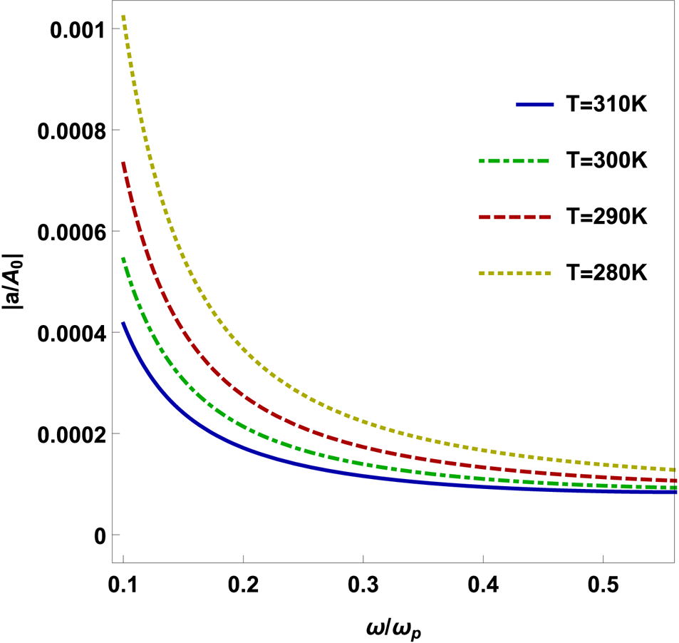
Figure 5. The amplitude ratio of THz SMP wave $|a/A_{0}|$ with respect to normalized THz frequency $\omega _{{\rm ce}}/\omega$
 for temperature $T = 280\,\text {K}$
 (yellow dotted line), $T = 290\,\text {K}$
 (green dot dashed line), $T = 300\,\text {K}$
 (red dashed line) and $T = 310\,\text {K}$
 (blue line) at normalized electron cyclotron frequency $\omega _{{\rm ce}}/\omega _{p} = 0.05$
 and other parameters $\mu = 0.3$
 , $\epsilon _{r} = 15.68$
 and ${h} = 50\,\mathrm {\mu }$
 m.
m.
6. Conclusion
In this paper, we propose the theoretical analysis of resonant excitation of THz SMPs by optical rectification of the modulated amplitude of SMPs in a magnetized rippled semiconductor (n-type). The current density generates THz SMPs at modulation frequency $\varOmega$ because of the ponderomotive force. Here, the ripple wavenumber gives an extra wavenumber for resonant excitation of the THz SMP wave. The THz SMP wave amplitude reaches its maximum value in the resonance condition and decreases in the non-resonant condition. It is observed that the THz SMP amplitude ratio rises as the normalized electron cyclotron frequency (external magnetic field) rises for normalized THz frequency. THz SMP amplitude ratio rises with a decrease in the normalized THz frequency. Further, it rises with a drop in semiconductor (n-type) temperature. This study could be used for THz devices for the excitation of THz waves at a desired THz frequency by changing the applied magnetic field and the semiconductor's temperature.
Acknowledgements
A.P. gratefully acknowledges the financial support from the Science and Engineering Research Board (SERB), India (CRG/2021/002187).
Editor Victor Malka thanks the referees for their advice in evaluating this article.
Declaration of interests
The authors report no conflict of interest.
Author contributions
Rohit Kumar Srivastav and Dr Anuraj Panwar developed the formulation of the manuscript. Rohit Kumar Srivastav prepared figures 1–5.


