


5.1 Fuel Cells and Electrolyzers
Hydrogen will play an increasingly important role in the push toward greater use of renewable energy and the reduction in carbon emissions from the transportation sector, electrical energy generation and transmission, and the production of commodity chemicals, such as ammonia and polyolefins. In this chapter, the operating principles of fuel cells and electrolyzers are detailed. The main function of these devices is the interconversion of electrical and chemical energy.
5.1.1 Basic Operating Principles
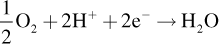
Electrochemical systems are identified by heterogeneous electron-transfer reactions. A fuel cell is such a system. There are two distinct electrodes separated by an ionic conductor that is electronically an insulator (Figure 5.1). These electrodes are referred to as the positive and negative electrodes. Rather than the combustion of hydrogen and oxygen, for example, two separate electron-transfer reactions take place in a H2/O2 fuel cell.
 (5.1)
(5.1)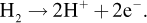 (5.2)
(5.2)The net reaction, obtained by summing the two electron-transfer reactions, is the combination of hydrogen and oxygen to produce water. The overall reaction may appear the same as combustion, but it is not a thermal process; and therefore, a fuel cell is not limited by the Carnot efficiency. At the negative electrode, hydrogen is oxidized. The protons are transported across the separator to the positive electrode. Electrons simultaneously travel to the positive electrode, but through an external circuit. At the positive electrode, oxygen reacts with the protons released from the oxidation of hydrogen and electrons that pass through the external circuit. At the positive electrode, oxygen is reduced to form water.
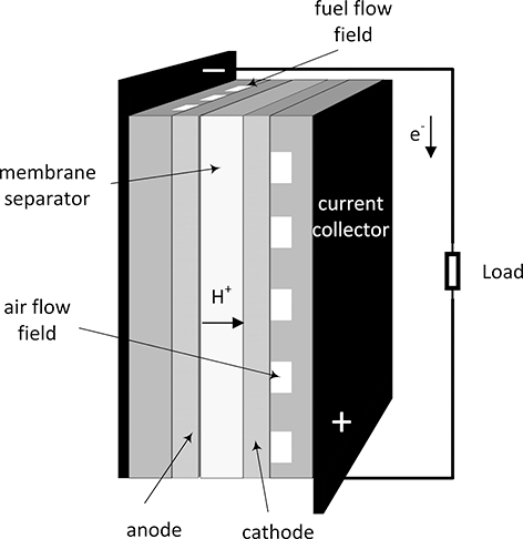
Figure 5.1 Cell sandwich of an acid fuel cell.
There is a potential difference between the electrodes. For instance, the potential of the oxygen electrode is about 1 V higher than that of the hydrogen electrode. It is this potential difference, which is proportional to the energy of the electrons, that allows current to flow through the external circuit and accomplish useful work. The electrode where oxidation takes place is called the anode, and where reduction occurs is called the cathode. For a fuel cell, the positive electrode is the cathode and the negative electrode is the anode. For electrolysis, which is discussed later, oxidation occurs at the positive electrode and reduction at the negative. In a rechargeable battery, the anode and cathode switch depending on whether the cell is being charged or discharged. For this reason, negative and positive electrode are preferred as these terms are unambiguous. Nonetheless, for a fuel cell the two electrodes are almost always referred to as the cathode and anode.
A battery may be a more familiar example of an electrochemical system, but fundamentally all electrochemical systems share common characteristic and can be analyzed similarly. Batteries, fuel cells, and electrolyzers can be thought of as electrochemical systems for energy conversion and storage. A rechargeable battery readily converts between chemical and electrical energy. The same conversions occur in fuel cells and electrolyzers, but for the most part these devices specialize in converting energy in one direction. A fuel cell converts chemical energy to electrical energy, and an electrolyzer converts electrical energy into a fuel or other desired product. Most batteries are sealed with only terminals to withdraw or add electrons. All of the active material that stores energy is contained in the housing, and this limits the amount of charge that can be stored. This is not the case with fuel cells and electrolyzers. Referring to Figure 5.1, fuel and air are supplied separately to the anode and cathode flow fields to be distributed over the area of the cell. As long as fuel and air are supplied, the fuel cell can operate indefinitely. Similarly, as long as reactants and electrical energy are provided, the electrolyzer can also generate product indefinitely. Thus, by definition a battery is a transient device. Fuel cells can and do operate transiently, but they can also be operated continuously at steady state. Operation time is a key factor in selecting between a battery and a fuel cell.
Finally, another system that shares characteristics of the electrolyzer and the fuel cell is the redox flow battery (Gencten and Sahin, Reference Gencten and Sahin2020; Wang et al., Reference Wang, Luo, Li, Wei, Li and Yang2013; Yuan et al., Reference Yuan, Song, Platt, Zhao, Wang, Li, Fatih and Jang2019). It is a battery in the sense that it stores and releases energy, but rather than holding the active material in the electrodes, the chemical storage occurs in the electrolyte. This electrolyte flows through the cell and a large volume of it is held in a tank. So, it’s a battery but with separate energy storage. As such the power and energy aspects of the system are decoupled.
Types of fuel cells: There are many types of fuel cells. These are generally categorized by the electrolyte used, which is closely related to the temperature of operation. The more common types are listed in Table 5.1. More details can be found in the literature (Fuller and Harb, Reference Fuller and Harb2018; Huang and Goodenough, Reference Huang and Goodenough2009; Mench, Reference Mench2008; O’Hayre et al., Reference O’hayre, Cha, Colella and Prinz2016). Each type has advantages and disadvantages. The focus here is limited to solid oxide (SOFC) and proton exchange membrane fuel cells (PEMFCs). The most important difference between SOFC and PEMFC is the temperature of operation. This difference drives materials selection, the importance of and types of catalysts, and the integration of the fuel cell into a larger system.
Table 5.1 Types of fuel cells
| Fuel cell type | Acronym | Electrolyte | Temperature |
|---|---|---|---|
| Proton exchange membrane | PEMFC | Proton conducting polymer (acidic) | 60–90°C |
| Alkaline | AFC | Strong base | 80–100°C |
| Phosphoric acid | PAFC | Phosphoric acid | 180–220°C |
| Molten carbonate | MCFC | Molten carbonate | 650°C |
| Solid oxide | SOFC | Oxygen conducting ceramic | 700–1000°C |
Regardless of type, the potential of a single cell is about 1 V. This voltage is too low for most applications. With a potential of only 1 V a current of 1000 A would be required to produce just a kilowatt of power, requiring large wires. Therefore, cells are electrically connected in series to increase voltage. Building voltage by connecting cells in series is also common in batteries. In batteries, this is accomplished by connecting the positive terminal of cell 1 with the negative terminal of the next cell in the string with external wires. This configuration is a monopolar design. In contrast, the predominant method of building voltage for fuel cells is with a bipolar stack, illustrated with Figure 5.2. Individual cells are stacked together like a deck of cards. A single metal plate connects the positive electrode of one cell with the negative electrode of the next cell in the assembly. There can be as many as two or three hundred cells assembled together in a single stack. The voltage of the stack is the sum of the voltages of the individual cells.
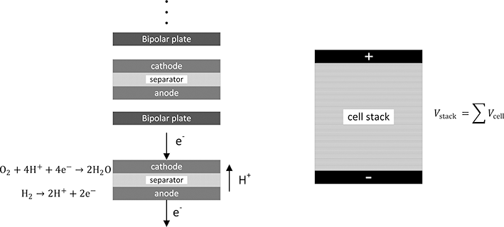
Figure 5.2 Bipolar configuration for a fuel-cell stack showing how voltage is built.
Reactants must also be provided to each individual cells. Most commonly fuel and air are manifolded so that the flow of reactants is in parallel to each individual cell. Air has to be provided to each and every cathode, and fuel is provided through separate manifolding to each of the anodes. As you will quickly recognize, in addition to the electrolyte, which also serves to separate the fuel and oxidant within the cell, a means of preventing mixing of reactants between cells is needed. The key component for the cell stack is what is known as a bipolar plate. This metal plate serves as a current collector and mates the positive electrode of a cell with the negative plate of the next cell in series. In practice, the bipolar plate can be a thin sheet of stainless steel coated for corrosion resistance. It needs to have good electrical conductivity, be sufficiently resistant to corrosion for the environment of the fuel cell, and most important be a barrier that prevents mixing of the reactants. Because of the supply of air and fuel to these cells, sealing is an important challenge as well.
In addition to the electrochemical device or fuel cell stack, subsystems are needed to meter fuel, supply air, provide cooling to the stack. Figure 5.3 is a highly simplified diagram of a PEMFC system operating on hydrogen. Even at high temperatures, fuel cells do not oxidize methane or higher order alkanes efficiently. Therefore, a reformer may be included when operating on hydrocarbon fuels in order to convert the fuel to hydrogen and carbon monoxide. A control system is necessary for automatic operation including start-up and shutdown. Often, power conditioning is part of the fuel-cell system. These other subsystems are referred to as the balance of plant (BOP) or ancillary equipment. Although the fuel cell itself has no moving parts, commonly used pumps, blowers, control valves, heat exchanger, and such comprise the balance of plant. These components are essential and influence the size and cost of the fuel-cell system.
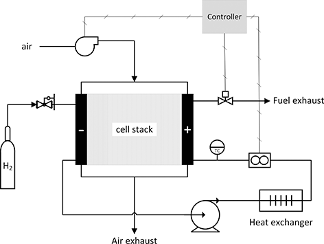
Figure 5.3 Simplified system for a proton exchange membrane fuel-cell operation on hydrogen and air.
We noted earlier that a fuel cell is not limited by the Carnot efficiency as is the case for gas turbines or reciprocating engines described in companion chapters. In principle, all of the available energy of the fuel can be converted to electrical work. The available work is given by the change in Gibbs energy (not the heating value) for the overall reaction. Further, this available work is related to the equilibrium or thermodynamic potential,  [V], with
 (5.3)
(5.3)where F is Faraday’s constant, and n is the number of electrons transferred in the reaction. This equilibrium value,  , is an important starting point for analysis. For a hydrogen and oxygen fuel cell at standard conditions, assuming water is produced as a gas, the standard potential is 1.184 V. This value puts an upper limit the maximum work that can be obtained from the fuel or, alternatively, establishes the minimum work that must be supplied to drive electrolysis, that is, the fuel cell in reverse, to produce hydrogen and oxygen from water.
Current and voltage characteristics: The most important relationship for the performance of an electrochemical device is the connection between current and potential. In fact, the study of electrochemical engineering is largely about understanding the correlation of current and potential. Because of this coupling of current and potential, it is possible to control potential or current but not both simultaneously for any electrochemical system. For a fuel cell, this relationship is best expressed with a polarization curve (Figure 5.4). Here, the potential of the cell is plotted against the current density of the cell. The current is normalized with the separator area so that the polarization curve is independent of the size of the cell. The highest possible value for potential would be the equilibrium or thermodynamic potential, U. There are irreversible losses associated with current flow that are called polarizations. The polarizations are categorized as kinetic, ohmic, and mass transport losses. These characteristics will be discussed in more detail in subsequent sections. Here we note that most of the time, catalytic limitations determine the practical bounds of efficiency for fuel cells and electrolyzers (Stamenkovic et al., Reference Stamenkovic, Strmcnik, Lopes and Markovic2017).
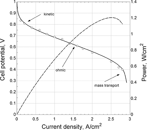
Figure 5.4 Polarization curve for a PEM fuel cell.
The potential of the cell is a good measure of its efficiency in converting chemical energy to electrical energy. The voltage efficiency of a fuel cell is defined as (Fuller and Harb, Reference Fuller and Harb2018) here
 (5.4)
(5.4)This efficiency uses the change in Gibbs energy in the denominator not the heating value of the fuel. Referring to the polarization curve, the power per unit area from the cell is the product of its potential and the current density, which is illustrated with the dashed line. As the current density is increased, the power density [W/cm2] increases and reaches a maximum and starts to decrease. It would not make sense to operate above the maximum in power. To the left of the maximum, as the power increases, the potential, and therefore the efficiency, decreases. Thus, we see that a key characteristic of a fuel cell is that it is most efficient at low power. This behavior is in contrast to many thermal cycles that are less efficient at low power. The cell can be operated at any point on the polarization curve. However, to achieve a prescribed power [kW], the size of the cell would need to be increased to achieve higher efficiency. It is the trade between size (cost) and efficiency that determines the optimum operating point.
5.1.2 Key System and Balance of Plant Challenges
Overview: Although the heart of a fuel-cell system is the cell stack, the entire system must be considered and the design integrated for any practical device. There is a lot of ancillary equipment. As an example, for the phosphoric acid fuel cell (PAFC), by volume or cost, roughly one-third of the power plant is the cell stack, one-third the reformer, and one-third the power conditioning. (Sammes et al., Reference Sammes, Bove and Stahl2004)
Material and energy balances are foundational to the analysis of fuel-cell systems. Using a hydrogen-air fuel cell operating at steady state as an example, the overall reaction is
 (5.5)
(5.5)Mass balances are made for each reactant and product. The amount of fuel supplied must equal the amount consumed in electrochemical reactions, plus any that is vented or permeates across the separator. Similarly, oxygen from air is provided. Given that 79% is nitrogen and argon, which don’t react, there will be a large exhaust stream. Air from the atmosphere is essentially free, other than the cost of pumping, but there are other reasons to control the amount of air supplied, which are discussed later. The products, here just water, also have to be balanced. This balance has important consequences for every type of fuel cell.
An overall energy balance is also informative. There is energy released from the overall reaction, described by the heating value of the fuel. Our goal would be to have as much of this energy go to electrical power ( ), but because of irreversible processes of ion conduction and reactions kinetics, some of this energy is released as heat. Therefore, it is common to include thermal management systems to maintain the desired temperature of the cell stack.
Depending on the application, a fuel-cell system may need to handle changes in power that span a large range as well as to respond quickly to changes in load. Most systems are designed to have minimal storage of reacts (fuel and air in the manifolds). The electrochemical device responds quickly, and it is the supply or reactants to support the current that limits the dynamic response. Therefore, careful control of air and fuel is required for smooth transient operation. Even if operation at steady state is planned, the system will experience transients during start-up and shutdown. In the discussion below, two specific aspects of the balance of plant challenges are explored: (1) water balance in PEM fuel cells and (2) thermal management in SOFCs.
PEM Fuel Cells: Proton exchange membrane fuel cells (PEMFCs) use a solid polymer material with covalently bound sulfonic acid groups as the electrolyte. A key characteristic of these materials is that they are only good ion conductors when water sorbs into the polymer material. With greater activity of water in the fuel and air streams, the water content in the membrane increases, and its conductivity increases. Good conductivity is essential to lower ohmic losses and maintaining efficient operation. Since water is produced in the fuel cell, this limitation in principle is not an issue. However, the vitiated air that leaves the cell carries water vapor out of the cell; and the greater the flowrates the more water that is removed. Also, as the cell temperature increases, the vapor pressure of water needed to maintain good conductivity of the membrane also increases. As a result, the higher the cell temperature, the greater the water removal. So, in addition to ensuring that sufficient air is provided for the electrochemical reactions, care must be taken not to remove so much water that the membrane dries out. This balance is described by Fuller and Harb (Reference Fuller and Harb2018) and is a key design constraint for air flow and temperature of operation for PEMFCs. Two other notes about PEMFCs. First, the membrane and catalyst are more or less intolerant of impurities from the fuel. Therefore, hydrogen for these fuel cells must be ultrapure (Ohi et al., Reference Ohi, Vanderborgh, Ahmed, Kumar, Papadius and Rockward2016). In contrast, solid oxide fuel cell, discussed below, offer fuel flexibility (Eguchi et al., Reference Eguchi, Kojo, Takeguchi, Kikuchi and Sasaki2002). Second, PEMFCs operate at temperatures of about 80°C. In automotive applications for example, heat rejection to the environment is a significant challenge, particularly because for PEMFC little heat is removed with the exhaust as compared to the internal combustion engine (Fronk et al., 2000; Nöst et al., Reference Nöst, Doppler, Klell and Trattner2018).
SOFC Fuel Cells: Solid oxide fuel cells (SOFC) present a different set of challenges. These cells rely on an ion conducting ceramic material for the electrolyte. To achieve acceptable ionic conductivity the temperatures must be 700–1000°C. Different from PEMFCs, the conductivity of the electrolyte is insensitive to water content in the fuel and oxidant streams (Huang and Goodenough, Reference Huang and Goodenough2009). Thus, controlling air flow to manage water is not needed. These high temperatures limit materials of construction and cooling options. A common means of controlling temperature for SOFCs is to use the air exhaust for heat removal. The flow rate of air is adjusted, always keeping it above that needed for the stoichiometry of the reaction, to remove the desire heat load.
With the bipolar stack configuration described previously, there are additional challenges with SOFCs. Not only is the material set limited, but it is critical to match the coefficients of thermal expansion (CTE) for different materials in the cell stack. Given the high temperature of operation, this restriction has limited the practical size of individual cells in a planar stack to about 100 cm2 and makes thermal cycling a particularly difficult issue. As a result, for a system operating on pure hydrogen, there is little incentive to use SOFCs over PEMFCs. However, the high temperature does allow SOFCs to be integrated better with reformers when a fuel such as methane is used instead of hydrogen (Huang and Goodenough, Reference Huang and Goodenough2009).
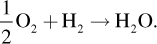
Design concepts and components: As was discussed earlier, the potential plotted in the polarization curve of Figure 5.4 is a measure of the voltage efficiency. Assuming other factors are unchanged, the higher the voltage efficiency the lower the operating costs (mainly fuel costs). However, the capital costs are roughly proportional to the separator area. For a fixed power, this separator area is given by
 (5.6)
(5.6)where  represents the current density [A/m2]. Higher level systems requirements are decomposed to an electrical power requirement for the cell stack. The size of the cell stack, in terms of separator area, is found in Equation 5.6. The product
  is in the denominator, corresponding to the dashed line in Figure 5.4. As is evident, greater efficiency (cell potential) results in a larger cell area. Figure 5.5, where the voltage efficiency is based on the polarization curve of Figure 5.4, shows that this area increases rapidly at low current densities, which corresponds to higher voltage efficiency. This sets up the key trade that is made in deciding on the operating point for the system, namely balancing operating costs (efficiency) against capital cost (cell area). Of course, this analysis is highly simplified, but it does illustrate the critical balance between operating and capital costs. A final note, both extremes, high and low current densities, are poor choices for the operating point. At low current densities, the cell area increases dramatically. At high current densities, the operating point is too close to a mass-transfer limit.
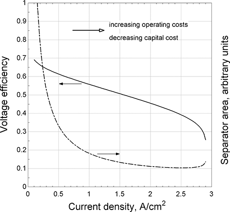
Figure 5.5 Simple trade between operating and installed costs.
Structural and mechanical considerations: Other than matching of CTEs for SOFCs (Lessing, Reference Lessing2007; Mahato et al., Reference Mahato, Banerjee, Gupta, Omar and Balani2015), the literature largely neglects the critical mechanical and structural consideration in the design of a cell stack. Fuller and Harb (Reference Fuller and Harb2018) introduce some of the important general aspects, but otherwise details appear to be proprietary to developers, and no systematic and complete guidance is provided. For a cell stack, the axial load must be controlled. Beyond just holding the stack of cells together, since there are hundreds of interfaces across which high currents flow, reducing contact resistance to a manageable level is essential. At the same time, the axial load cannot be too high because it will result in excessive creep of the cell components (Borup and Vanderborgh, Reference Borup and Vanderborgh1995; Solasi et al., Reference Solasi, Huang and Reifsnider2010). Regardless, some creep will occur over the life of the cell stack. Thus, the means of providing axial load must allow for some changes in dimensions over time. It is also critical that the axial load be uniform over the entire cell area. This requirement places tight tolerances on the dimensions of the individual cell components as well as the load system. Lastly, it is noted that there can be an enormous length of seals in a large cell stack. These require careful design as well.
5.1.3 Key Performance Metrics that Distinguish Good and Bad Operation
The polarization curve in more detail: The polarization curve is the most important description of the performance of the fuel cell. Its analysis begins with the equilibrium potential of the cell. This is expressed as a standard potential,  , based on the standard change in Gibbs energy,
  .
.
 (5.7)
(5.7)Of course, the actual environment will be different from idealized standard conditions. First, the common standard state is 25°C. Because the overall reaction is exothermic, this thermodynamic potential will be lower as the temperature is increased. A second correction, for composition, is made with the Nernst equation
 (5.8)
(5.8)where a represents the activity of the species. For a gas, this activity is approximated by  , where
  is the pressure at the standard state, 100 kPa, and
  is the partial pressure of species i. The value here is still a thermodynamic one; that is, one where there is no current flow and the kinetics for the reactions assumed to be infinitely fast. Taking the product water as an ideal gas, the standard potential is
  V. Equation 5.8 corrects for the composition. If the partial pressure of oxygen decreases, then the equilibrium potential also decreases.
When current flows, the voltage of the cell is
 (5.9)
(5.9)The terms on the right side after the equilibrium potential are called polarizations: namely, the ohmic or iR loss, the kinetic overpotentials for the anodic and cathodic reactions, and lastly a concentration overpotential. Notably, all of these are associated with irreversible processes, and all reduce the potential of the cell. Each of these polarizations depends on the current density. For a PEM fuel cell, the polarization curve shown in Figure 5.4 is typical. The reduction of oxygen in acid is notoriously sluggish. Even with precious metal catalysts, at low current densities, the kinetic polarization of the oxygen reduction reaction is large (>0.2 V), but there is an exponential relationship between current and the overpotential. As a result, the rate of increase of kinetic overpotential becomes smaller and smaller with increasing current density. In contrast, ohmic losses are linear with current density. Thus, we see that different portions of the curve are dominated by different polarizations. At low current densities, kinetic polarization controls, then ohmic, and finally mass transfer. At high enough current densities, the concentration of reactants at the electrode decreases toward zero. When the mass-transfer limit is met, no matter how much the potential of the cell is reduced, no additional current can be drawn.
Looking back to the electron-transfer reactions presented in Equations 5.1 and 5.2, it is evident that three phases are present: gas phase, electrolyte that conductions ions but not electrons, and a solid phase for electron conduction. The electrodes shown in Figure 5.1 are not simple flat surfaces, but rather they are porous electrodes. The main objective of electrode design is to reduce the polarizations noted in Equation 5.9. The details are beyond our scope, but electrode designs would be different for different types of fuel cells and for different applications. For instance, the high temperature of operation found in a SOFC generally results in small kinetic overpotentials. On the other hand, a PEMFC that operates at low temperature may have a large kinetic overpotential. Equation 5.9 is a description of the polarization curve, which may be developed theoretically or measured experimentally. Regardless of how it is obtained, this relationship is critical to the determination of the operating point of the cell.
Finding the optimum operating point typically would include an analysis of the entire fuel-cell system. The basic ideas, nonetheless, can be seen just looking at the cell stack. A single objective function is possible, but not common. An example where of a single objective is the mass of a fuel-system that includes mass of hydrogen and oxygen for a space application. In this case study (Fuller and Harb, Reference Fuller and Harb2018), because the cost of overcoming earth’s gravity is so large, minimizing system mass is paramount. In most cases, there will be multiple objectives: efficiency, volume, mass, cost, turn-down capabilities. These details are beyond our scope. Nevertheless, the main balance is between efficiency and size, or said another way between fuel or operating cost and capital cost.
Efficiencies: We have discussed the voltage efficiency of a cell. There are several additional efficiencies for the fuel-cell system that are useful. Here, we envision taking a fuel and producing regulated power. The system efficiency is most often expressed in terms of a thermal efficiency. Rather than the Gibbs energy, the heating value of the fuel is used. This practice has been adopted even though the fuel cell is not a thermal device limited by the Carnot efficiency.
 (5.10)
The lower heating value is used by developers when quoting efficiencies irrespective of the actual conditions of the water in the system. Presumably this choice is made because it results in a higher efficiency. As is discussed more below, as a practical matter not all of the fuel supplied contributes to current in the fuel cell, which leads to a fuel efficiency.
 (5.11)
Two other efficiencies are defined: the power conditioning efficiency,
 (5.12)
and the mechanical efficiency,
 (5.13)
Power conditioning efficiency is a recognition that unregulated DC power from the fuel cell must be converted to AC power with constant voltage irrespective of the load. The mechanical efficiency accounts for any electrical power that is needed to drive blowers, operate cooling pumps, and power control systems as examples of ancillary equipment needed for the system. These can then be related back the voltage efficiency from the polarization curve.
 (5.14)
Here  is the thermal voltage efficiency, which is just the voltage efficiency based on the heating value of the fuel instead of the change in Gibbs energy. So, if a particular thermal efficiency is identified, Equation 5.14 indicates what cell potential,
  , is needed. Further, effects of fuel utilization and mechanical efficiency are evident. As expected, better utilization of fuel, fewer mechanical losses, and greater power conversion efficiency are desired.
Specific power and power density: Though fuel cells can be combined with a fixed amount of fuel to act like an energy storage system, fuel cells are usually treated as energy conversion devices. The size is categorized with power and more specifically power density [kW/L] or specific power [kW/kg]. Fuel-cell systems are semicommercial. Consequently, it is difficult to establish definitively the present state of the art. A recent study sought the opinions of experts in the field to estimate the present state and in the future for PEMFC. The report from the experts focused on transportation where volume is more important than mass (Whiston et al., Reference Whiston, Azevedo, Litster, Whitefoot, Samaras and Whitacre2019). The report identified the power density to be 2.5 kW/L (2017) and only increasing to 3.0 by 2050. This small increase reflects that without new breakthroughs, improvements in power density are likely to be incremental. The same study indicated that costs for PEMFC produced in large volumes would decrease from 75 to about 35 $/kW over the same period of time.
Transient behavior: Most applications of fuel cells require load following, but by design may allow for only modest rates of change. Even in a fuel-cell vehicle, a hybrid power system is preferred. The addition of a storage battery allows for energy recovery during braking, and reduces short-term transient demands on the fuel cell. Fuel cells can dynamically follow loads – the greatest design challenge for transient operation is providing fuel and oxidant to match the changes in current in the cell. The volume of fuel, or fuel inventory, in the cell stack is small. As a result, the dynamics of increasing reactant flows limit the transient response. This design constraint is particularly acute because the cells are electrically connected in series. To prevent severed damage, it is critical that each cell receives the requisite fuel to support the current draw. This is true at steady state as well as during a transient; again, the challenge is exacerbated by the small fuel inventory in the manifolds and flow channels of the stack. Thus, fuel flow to each and every cell must ramp up at the same time as the change in current.
In stationary applications, fuel cells are usually grid connected. This mitigates the transient capability required of the fuel-cell system. Fuel cells can be and are designed to operate independent of the grid (King and O’Day, Reference King and O’Day2000). A lot of the literature focuses on small laboratory tests that may not be particularly relevant.
Start-up and Shut down: If not designed properly, starting and stopping fuel cell systems can result in damage to the fuel-cell stack. The details are specific to the type of fuel cell. A well-known instance for PEMFCs is described by Reiser et al. (Reference Reiser, Bregoli, Patterson, Jung, Yang, Perry and Jarvi2005): the reverse-current mechanism, but fundamentally this is caused by not sufficiently controlling hydrogen at the anode during the transient. As they are being considered for transportation applications, starting from freezing conditions is also an important consideration for PEMFCs (Rice, Reference Rice2021). Solid oxide fuel cells bring a different set of challenges. The high operational temperature limits the speed at which the cells can be started, thermal gradients need to be minimized to prevent structural failure from mismatches in thermal expansion coefficients (Zheng et al., Reference Zheng, Kuang, Rao and Shen2019).
Durability: The useable life of a fuel cell is critical in determining its economic viability of electrochemical systems, which is considered in Section 5.2.3. Durability has been a focus for academia and industry, and there is an extensive literature on both PEM (Borup et al., Reference Borup, Kusoglu, Neyerlin, Mukundan, Ahluwalia, Cullen, More, Weber and Myers2020; Wu et al., Reference Wu, Yuan, Martin, Wang, Zhang, Shen, Wu and Merida2008) and SOFC (Pan et al., Reference Pan, Yang, Yan, Pu, Chi and Li2020; Reifsnider et al., Reference Reifsnider, Ju and Huang2007; Yokokawa, Reference Yokokawa2011; Yokokawa et al., Reference Yokokawa, Horita, Yamaji, Kishimoto and Brito2010) durability as well as a large number of patents issued. The mechanisms for performance decay are many and varied. The interested reader is referred to the literature cited. The same study cited above for performance (Whiston et al., Reference Whiston, Azevedo, Litster, Whitefoot, Samaras and Whitacre2019) indicated that durability for PEMFC would increase from 4000 to 8000 hours from 2017 to 2050.
5.1.4 How Fuel Composition Affects Operation
We’ve already seen one aspect of the impact of composition, namely the Nernst equation (Equation 5.8). By increasing the concentrations of the reactants, the potential of the cell rises. This is a thermodynamic effect. There are similar benefits in terms of kinetics and mass transport. As a general rule, raising the concentration of reactants improves the voltage efficiency of the cell. It is also the case that higher concentration of reactants raises the mass-transfer limit, which in turn increases the maximum power that is achievable.
Utilization effects: However, maintaining a high concentration of reactants also has a price. Before we discuss this in more detail, the concept of reactant utilization is introduced. The oxygen and fuel utilization are defined,
 (5.15)
 (5.16)
By its definition, utilization can range from 0 to 1. It is also the inverse of the stoichiometry. If twice the air is provided compared to that required by the reduction of oxygen in the cell, this is a stoichiometry of 2, or an oxygen utilization of 0.5.
We’ve seen from the previous discussion of efficiency, that any fuel that does not contribute to the current reduces the system efficiency. Of course, it is desirable to consume all of the fuel in the cell; however, this is not practical. One option is to integrate the fuel cell with a thermal heat engine that operates on the unused fuel. Here, our focus is to maximize the use of the fuel in the electrochemical device. The key issue is that as the concentration of the fuel is reduced, transport limitations grow, and the concentration polarization increases. This polarization results in a loss of efficiency, but more important in the case of fuel can lead to damage of cells in a bipolar stack.
The effect of consuming a large fraction of oxygen from air has a similar effect on transport limitations. This impact is shown in Figure 5.6, where polarization curves are shown for different values of oxygen utilization. The main change is in the mass-transfer region at high current densities. Because air is only 21% oxygen, this utilization effect is magnified. As a result, it is unusual to find oxygen utilizations greater than 0.5 or 0.6. Even if pure hydrogen is used, because of diffusion of nitrogen from the air across the separator, a condition called crossover, nitrogen builds up in the anode side. Consequently, hydrogen systems required periodic purges to eliminate non-reacting gases.
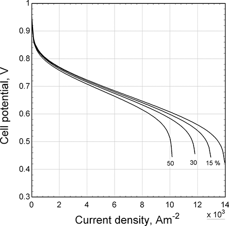
Figure 5.6 Effect of oxygen utilization on the polarization curve.
Integration of system with fuel reformer: For the cathode side, where oxygen is obtained from the atmosphere, increasing the flowrate of air doesn’t have a dramatic effect on efficiency that fuel utilization does on energy efficiency. There is still some power required to force the air through the cells. Usually, other factors come to play: for example, we discussed earlier how air flow affects the water balance in PEMFCs, and how air flow is used to cool SOFCs.
For systems that use a hydrocarbon fuel that is reformed, the feed to the cell stack is a mixture of hydrogen, carbon monoxide, carbon dioxide, and water. Since the carbon dioxide is fully oxidized, it cannot be further oxidized; essentially, it is a diluent, creating the same challenges with utilization and mass transfer found on the air side. Whereas exhausting vitiated air has a small effect on system efficiency and is acceptable, venting fuel is not a design option. The solution is found by integrating the fuel utilization in the cell stack with the reformer. Reforming is an endothermic process, and the heat must be supplied to drive the reaction to completion. Unused fuel from the cell stack is simply combusted to drive the reforming process (Fuller and Harb, Reference Fuller and Harb2018).
Utilizations of fuel and oxygen, as discussed in the previous section, are critical design choices. Though defined generically in Equations 5.15 and 5.16, utilization of reactants and oxygen must be considered from a system level, a stack level, and even an individual cell level. This is particularly true for the fuel. Recall, that with a bipolar configuration, reactants are provided to all cells in parallel, but current flows through them in series. Thus, the same current is flowing through each cell; and from Faraday’s law the same amount of fuel is being consumed in each cell. As a consequence, if one cell is receiving more or less flow or reactants than other cells in series, the utilization in the cell will be different. Just as with oxygen the cell performance is affected (Figure 5.6). For bipolar stacks, the performance of the stack is only as good as the weakest performing cell. There is, however, an even greater risk. When there is not enough fuel to a particular cell, a condition call fuel starvation can occur. Under these conditions, permanent damage to the cell can occur (Fuller and Harb, Reference Fuller and Harb2018). As a consequence of this risk, the manifolding, flow channels, and fuel delivery systems have to be designed carefully to avoid conditions where fuel starvation might occur. Computational fluid dynamics (CFD) is used extensively in tandem with testing to validate system, stack, and cell designs (Danilov and Tade, Reference Danilov and Tade2009; Jeon et al., Reference Jeon, Greenway, Shimpalee and van Zee2008).
5.2 Chemical Energy Carrier Options
A chemical energy carrier (CEC) is a method of storing energy in a chemical form that is more easily transported. By means of forming and breaking chemical bonds, energy is stored and released for use in a different place at a different time. Pivovar et al. (Reference Pivovar, Rustagi and Satyapal2018) motivate the choice of the chemical energy carrier on the basis of the strength of the chemical bonds, the kinetics associated with breaking the bonds, and the availability of the sources the materials. They and others argue for hydrogen (Crabtree et al., Reference Crabtree, Dresselhaus and Buchanan2004), but other notable compounds being considered are ammonia (Miura and Tezuka, Reference Miura and Tezuka2014) and methanol (Olah, Reference Olah2004). The motivation for a CEC is clear – matching the demand and supply of renewable energy. A secondary battery, such as a lithium-ion cell, converts between electrical and chemical energy. However, given that the specific energy density of gasoline, for example, is about 100 times larger than that of a storage battery, alternate means of chemical storage and transport are sought (Chu et al., Reference Chu, Cui and Liu2017). Key aspects are the ease of formation of the chemicals, their ability to store energy, the suitability for transportation, and finally the conversion of the stored energy to use.
Figure 5.7 shows a system for the production of a CEC by electrolysis. Carbon dioxide and water provide the feed to the electrolyzer stack. When excess electrical power is available, it can be used to drive the electrochemical reduction of the feed. As discussed in the previous section on fuel cells, consuming all of the reactants in a single pass is not possible, and some of the product stream is recycled. The electron is, for all intents and purposes, a feedstock to the electrochemical process. With the growth of renewable sources of electricity such as wind and solar power, it is anticipated that the levelized cost of clean electricity will continue to drop (Chu et al., Reference Chu, Cui and Liu2017). As lower cost electricity from renewables becomes available, it may be cost effective and convenient to store this electrical energy in the form of a chemical fuel. Electrochemical systems, such as electrolyzers and fuel cells, are a means by which energy is converted between chemical and electrical forms. The focus here is limited to the electrochemical production of hydrogen and carbon monoxide as a route to chemical fuels (Stamenkovic et al., Reference Stamenkovic, Strmcnik, Lopes and Markovic2017). These two chemicals are both used on an industrial scale, and further, synthesis or syngas provides many chemical paths to raw materials for plastics and for liquid fuels, through the Fischer–Tropsch process for example. Second, the electrochemical reduction of carbon dioxide to carbon monoxide is a means to reduce the carbon dioxide footprint for petrochemical production.
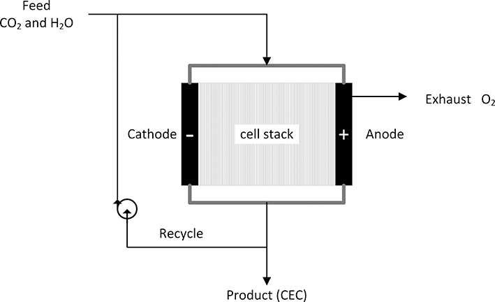
Figure 5.7 Using electrolysis to create a chemical energy carrier.
5.2.1 Electrochemical Production of Fuels
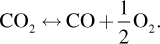
Generally, the electrochemical production of fuels consists of the reduction of carbon dioxide or water to produce chemical fuels. Excluding ammonia as a fuel, the overall reaction for hydrocarbons can be generalized (Fuller and Harb, Reference Fuller and Harb2018),
 (5.17)
In principle, this approach is an attractive method to produce chemical fuels that serves as a chemical energy carrier and at the same time to mitigate the effects of emissions of carbon dioxide (Chu et al., Reference Chu, Cui and Liu2017). Two important examples that will be considered in more detail are the reduction of water to produce hydrogen  and the reduction of carbon dioxide
  to produce carbon monoxide,
 (5.18)
It is important to remember that for electrochemical processes, there are two distinct electron-transfer reactions that occur simultaneously: oxidation and reduction. For example, in an oxygen ion conductor, the reduction of CO2 occurs by two electron-transfer reactions. At the cathode, carbon dioxide is reduced to form carbon monoxide and an oxygen ion,
 (5.19)
These oxygen ions move across the separator where they are oxidized (giving up electrons) to produce oxygen gas.
 (5.20)
The electrons that are released travel through an external circuit back to the cathode, where they are consumed in the reduction process. Before looking at the electrochemical production of hydrogen and carbon monoxide in more detail, the fundamentals of electrolysis are presented and compared to fuel cells.
5.2.2 Basic Operating Principles
Electrolysis may be thought of as a fuel cell operating in reverse. This view is particularly apt in the context of a chemical energy carrier, such as hydrogen. As with a fuel cell, there is an anode, a cathode, and an ionically conducting separator that is also an electronic insulator. Either carbon dioxide, water, or both are supplied to the negative electrodes of the cell stack. At the cathode (negative electrode for electrolysis), carbon dioxide or water is reduced. At the positive electrode (anode for an electrolyzer), an oxidation process occurs. Typically, this is the generation of oxygen.
The figures of merit, or quantities that characterize the performance of electrolyzers, are analogous to those used for fuel cells; though, some differences do exist. The connection between current and voltage, or the polarization curve, is still the essential relationship. The voltage efficiency for electrolysis is represented as
 (5.21)
which is the inverse of the definition for voltage efficiency of a fuel cell. As defined, the voltage efficiency for electrolysis will always be less than one. This expression can be thought of in terms of energy or power; however, the value depends on the operating current. The potential of the cell,  , is the voltage above the equilibrium potential that must be applied to drive the reaction. Compare Equation 5.22 with Equation 5.9.
 (5.22)
As with a fuel cell, the difference between the equilibrium potential and the cell potential can be attributed to polarizations: ohmic, kinetic, and concentration. Here, however, each of these polarization results in a larger cell potential and, therefore, a lower voltage efficiency for electrolysis. Further, these polarizations increase with increasing current, and consequently as the cell is operated at higher currents, the voltage efficiency decreases, similar to what is found with a fuel cell.
It is possible that other species are formed in addition to the desired product from electrolysis. A critical parameter for electrolysis cells is the faradaic efficiency,
 (5.23)
Faraday’s law relates the coulombs of charge passed to the amount of material produced in the electron-transfer reaction. Of course, a high value for faradaic efficiency is desired, but there can be several reasons why the faradaic efficiency is not one. Most important among them, there can be other reactions that occur in parallel, called side reactions. For instance, for the reduction of carbon dioxide in acid, hydrogen evolution is a competing cathodic reaction.
 (5.24)
 (5.25)
Some of the applied current may go to the production of hydrogen instead of carbon monoxide. In addition to this current efficiency effect caused by competing electron-transfer reactions, there are other means by which the products may not be recovered. As an example, a small amount of the product may permeate through the separator where it is chemically converted back to the starting material. A couple of additional points about the faradaic efficiency are noted.
First, the faradaic efficiency depends on what is deemed as the desired product. Many times, this is obvious. In the example above, however, the desired product could be hydrogen, it could be carbon monoxide, or even a specific ratio of CO and H2 (syngas). Understanding the precise definition for the faradaic efficiency is important. Second, there can be different products associated with each electrode. As an example, the chlor-alkali process produces both chlorine (Cl2) and caustic (NaOH(aq)) on an industrial scale (Fuller and Harb, Reference Fuller and Harb2018; Hine, Reference Hine2012). Both are valuable commodities. In this case, separate faradaic efficiencies for each product would be appropriate. There is no fundamental reason that these would be the same.
Another key metric for electrochemical production of a fuel is the energy efficiency of the process. This efficiency is simply the product of the faradaic efficiency and the voltage efficiency. It can be thought of as the available energy from the fuel relative to the electrical energy that was required to produce the fuel.
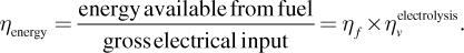 (5.26)
Here, the efficiency is defined in terms of the thermodynamic potential, U, which is related to the change in Gibbs energy not the heating value of the fuel. This convention makes sense for electrochemical systems because they are not thermal processes and are not limited to the Carnot efficiency, though defining an efficiency in terms of heating value is also possible.
Lastly, one additional consideration about faradaic efficiency is noted as particularly important. Our focus is on the electrochemical system. However, the electrolyzer may be a subsystem in a larger process. If our electrochemical system produces ammonia or formate with a low faradaic efficiency, not only does this reduce the energy efficiency of our electrochemical system, but it is likely that a downstream separation process would be needed to purify the product. This separation process can have a dramatic influence on the economics of the process. More details on electrolysis can be found in the literature. The work of Hine is notable in that he pioneered the treatment of electrolysis as a typical chemical process with electrons as the feedstock (Fuller and Harb, Reference Fuller and Harb2018; Hine, Reference Hine2012; Pletcher and Walsh, Reference Pletcher and Walsh2012).
5.2.3 Techno-Economic Analysis, Importance of Cost of Electricity, and Useable Life
The cost of raw materials or feedstock, the capital expense for the electrochemical system, fixed and variable operating costs, such as the cost of electricity, maintenance and the value of the material produced are key to any economic analysis. A number of articles relevant to electrochemical systems have been published (Bushuyev et al., Reference Bushuyev, De Luna, Dinh, Tao, Saur, van de Lagemaat, Kelley and Sargent2018; Shaner et al., Reference Shaner, Atwater, Lewis and McFarland2016; Spurgeon and Kumar, Reference Spurgeon and Kumar2018; Tremel et al., Reference Tremel, Wasserscheid, Baldauf and Hammer2015; Verma et al., Reference Verma, Kim, Jhong, Ma and Kenis2016), and the analysis here is rudimentary. The fuel is treated as a product, and the net margin (NM) is
 (5.27)
Details of inflation, discount rate, and taxes are ignored – our focus is on understanding how the characteristics of the electrochemical system influence the operating costs and capital expense. In terms of economics, the most important factor for commercial electrolysis is the cost of electricity.
Assuming a rate of production of the fuel kg/h, Faraday’s law can be used to convert this rate to a minimum number of coulombs per second that are required, which of course is the current, [C/s] or [A]. If, however, the faradaic efficiency is less than one, additional current must be applied,
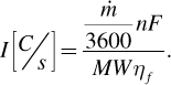 (5.28)
The electrical energy is the product of the current and the voltage. Thus, the selection of the operating potential is critical. As has been stated many times, the current and potential are related with the polarization curve, and further this choice of the operating point balances operating costs and capital expense. The electrical power is
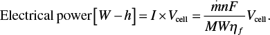 (5.29)
To minimize electrical costs, the potential of the cell should be as small as possible and the faradaic efficiency as large as possible. Faradaic efficiency can change with the operating point on the polarization curve, but more important is how capital expense is affected by the current density of operation. Recall that the polarization curve uses current density, i [A/m2]. Thus, the separator area, A, is given by
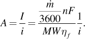 (5.30)
The current density determines how much separator area is needed, which more or less corresponds to the size of the electrolyzer and thus its capital expense. The situation here is analogous to that described for a fuel cell (Figure 5.5).
Whereas the stack costs are roughly linear with cell area, the balance of plant is nearly constants for a fixed rate of production. To maximize the NM, there is a balance between lowering the operating costs of the electricity and keeping the capital expenses from increasing dramatically. Another key factor in making this trade-off is the operating life of the electrochemical system. As the useful life is increased, the capital expense becomes less and less important compared to the electrical costs. Often values as high as 20 years or more are targeted, which are in principle achievable. It is worth noting that the most successful industrial electrolysis systems, chlor-alkali and aluminum production, undergo extensive repairs and component replacements every 5 years or less (Hou et al., Reference Hou, Chen, Guo, Dong, Wang and Xia2018; Prasad, Reference Prasad2000).
As discussed earlier, cells are going to be connected in series. Once the operating point is fixed (current density), the total cell area does not change with how the cells are configured (Equation 5.30). Placing cells electrically in series does reduce the area of a single cell, and therefore the current is lower. At the same time, the voltage of the stack increases. As a first approximation, we stated that capital expense was linear with cell area. There are practical limits to the area of cells and the number that can be assembled into a stack based on the technology. As cells are made smaller, there are more parts to assemble and more connections, both electrical and fluidic, that need to be made. Therefore, as the size of the cells is reduced, costs go up for the same total area.
5.3 Hydrogen
On earth most hydrogen is found in water – there is only a trace of molecular hydrogen in the atmosphere where it is an odorless and colorless gas. Hydrogen is produced in industrial quantities and used primarily as a feedstock for (1) hydro-processing, a generic term where hydrogen is used to remove undesired components from refinery steams (Hemighaus et al., Reference Hemighaus, Boval, Bacha, Barnes, Franklin, Gibbs, Hogue, Jones, Lesnini, Lind and Morris2007) and (2) ammonia production (Pivovar et al., Reference Pivovar, Rustagi and Satyapal2018).
Table 5.2 provides a summary of the properties of hydrogen, particularly those that are relevant to its use as a chemical energy carrier. The amount stored energy is represented with the heating value of hydrogen, 119.9 MJ/kg. For use as a chemical energy carrier the ability to store energy relative to the mass as well as the volume are important, namely specific energy [MJ/kg], and energy density [MJ/m3]. Being the lightest molecule, hydrogen has the highest theoretical specific energy of any fuel – the energy density is another story.
Table 5.2 Hydrogen properties relevant to its use as an energy carrier
| Molecular weight | 2.01588 g/mol (NIST Chemistry WebBook, SRD 69, n.d.) | Liquid density | 70.92 kg/m3 |
| Normal boiling point | –252.8°C | Enthalpy of vaporization | 418.5 kJ/kg |
| Critical temperature | –239.97°C (NIST Chemistry WebBook, SRD 69, n.d.) | Heat of combustion (LHV) | 119.9 MJ/kg (Smith et al., Reference Smith, Ness, Abbott and Swihart2018) |
| Critical pressure | 1.3 MPa (NIST Chemistry WebBook, SRD 69, n.d.) | Explosive limits in air | 4%–74% |
| Heat capacity | 14.3 kJ/kg-K |
Hydrogen has a critical temperature and pressure of −239.978°C and 1.3 MPa. Under typical atmospheric conditions it is a gas. The specific volume, which is the inverse of density, of hydrogen gas at 25°C is plotted in Figure 5.8. Even at extremely high pressures, the density of hydrogen is less than a tenth that of water or liquid hydrocarbons. Using this specific volume, the theoretical energy density is also shown in Figure 5.8. The pressures considered range from atmospheric to 70 MPa, which corresponds to the fuel tanks used in the Toyota Mirai, a semicommercial fuel-cell powered sedan.
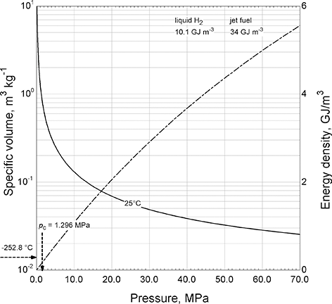
Figure 5.8 Specific volume and energy density of hydrogen gas.
Hydrogen gas is a liquid only at extremely low temperatures; the normal boiling point is −252.8°C. Thus, the energy density for liquid hydrogen is 10 GJ/m3, and that of compressed hydrogen (70 MPa, 25°C) is 5.6 GJ/m3. Jet fuel, for comparison, with a density of roughly 800 kg/m3, and a typical heat of combustion of 43 MJ/kg, (Hemighaus et al., Reference Hemighaus, Boval, Bacha, Barnes, Franklin, Gibbs, Hogue, Jones, Lesnini, Lind and Morris2007) results in an energy density of 34 GJ/m3. Therefore, the energy density of compressed and liquid hydrogen is significantly lower than that of liquid hydrocarbon fuels.
Another critical aspect for hydrogen as an energy carrier is safety. It can be argued that hydrogen is no more dangerous than gasoline, only that the risks and mitigations are different. The explosive limits in air are broad, ranging 4%–74%; however, because of its low density as a gas and the high diffusivity of hydrogen molecules, its speed in air is roughly 20 m/s at room temperature (Møller et al., Reference Møller, Jensen, Akiba and Li2017); any hydrogen that leaks is quickly dispersed.
Transport and Storage: Similar to other industrial gases, hydrogen is transported by pipeline or in trucks and ships, or by rail in large containers. There are some 1600 miles of pipeline dedicated to hydrogen in the US (Pivovar et al., Reference Pivovar, Rustagi and Satyapal2018) and more than 1000 miles of pipeline in Europe (Gillette and Kolpa, 2008). These pipelines are concentrated in the Gulf region where major refineries are located. Pressures are generally below 7 MPa. The technology is mature – though economically justified only in cases of high rates of demand.
For applications with smaller usage, transport in containers carried by trucks is more common. Most hydrogen is transported in steel cylinders or refrigerated tube trailers (Brown, Reference Brown2019). The greater the distance the more economical it is to transport liquid hydrogen because the greater density of the liquid allows more hydrogen to be carried. Boil-off rates for cryogenic systems are less than 1% per day (Brown, Reference Brown2019).
There are many needs for the storage of hydrogen, ranging from on board fuel for a fuel-cell vehicle to strategic reserves for hydroprocessing as examples. Most applications require gaseous hydrogen, and compressed gas is the most common means of storage. In addition to this physical method, chemical approaches of storage are also being pursued. Hydrogen storage has been the topic of many reviews (Abe et al., Reference Abe, Popoola, Ajenifuja and Popoola2019; Møller et al., Reference Møller, Jensen, Akiba and Li2017; Moradi and Groth, Reference Moradi and Groth2019).
The primary chemical approach is with metal hydrides (Jensen et al., Reference Jensen, Akiba and Li2016). This technology is of particular importance to the transportation sector as metal hydrides offer to improve the volumetric storage of hydrogen compared to compressed hydrogen. Further, they operate at low pressures, reducing the safety hazards. Despite years of development of metal hydrides, present fuel-cell vehicles use compressed hydrogen, with 5 kg of hydrogen being a common size for a passenger vehicle. However, it is estimated that compression to 70 MPa consumes more than 10% of the available energy from the fuel (Jensen et al., Reference Jensen, Vestbø, Li and Bjerrum2007). Hydrogen storage is recognized as an impediment to the use of fuel cells in transportation applications.
Large-scale storage of energy is increasingly important as society relies more on renewable energy sources (Hassanpouryouzband et al., Reference Hassanpouryouzband, Joonaki, Edlmann and Haszeldine2021). Similar to the strategic petroleum reserve, geologic storage of hydrogen in salt domes and depleted oil fields is being explored (Lankof and Tarkowski, Reference Lankof and Tarkowski2020). Hassanpouryouzband et al. estimate that for most countries the capacity for seasonal energy storage can be achieved with one large depleted gas field. Three geologic facilities are in operation in the US today (Pivovar et al., Reference Pivovar, Rustagi and Satyapal2018). Air Liquide operates a facility in Beaumont, Texas capable of holding enough hydrogen to supply a large-scale steam methane reformer (SMR) unit for 30 days (Liquide, Reference Liquide2017). The salt cavern is located 1500 m underground and has a diameter of almost 70 m.
Current production of hydrogen from natural gas: Hydrogen as an energy carrier is thought to have an important role in decarbonizing transportation, industry, and the grid (Abe et al., Reference Abe, Popoola, Ajenifuja and Popoola2019; Pivovar et al., Reference Pivovar, Rustagi and Satyapal2018). In this context, the production of hydrogen is sometimes categorized in terms of the method of production and further quantified with a hydrogen cleanness index (HCI) (Dawood et al., Reference Dawood, Anda and Shafiullah2020; Yu et al., Reference Yu, Wang and Vredenburg2021). Broadly, hydrogen produced from fossil fuels is grey, from fossil fuels with carbon capture and storage is blue, and from renewable energy is green.
The present production of hydrogen is estimated to be more than 100 Mtonnes per year (Franchi et al., Reference Franchi, Capocelli, de Falco, Piemonte and Barba2020). The production and uses of hydrogen are illustrated in Figure 5.9. Today, 95% of hydrogen is produced from fossil fuels, either steam reforming of natural gas, coal gasification, or other means related to the petrochemical industry (Franchi et al., Reference Franchi, Capocelli, de Falco, Piemonte and Barba2020). The process usually occurs through multiple chemical reactors, but generically, the steam reforming of natural gas is
 (5.31)
Thus, for each molecule of methane consumed a molecule of carbon dioxide is produced. Roughly, just 5% of hydrogen is produced electrochemically. With such a small amount produced by electrolysis, hydrogen production results in the release of about 830 Mtonnes of carbon dioxide per year (Franchi et al., Reference Franchi, Capocelli, de Falco, Piemonte and Barba2020). This amount is equivalent to the emissions of the United Kingdom and Indonesia combined (IEA, 2021).
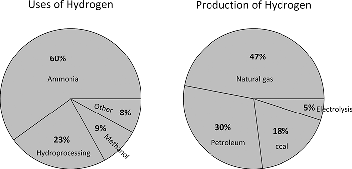
Figure 5.9 Pie chart showing uses of hydrogen based on Rosen and Koohi-Fayegh (Reference Rosen and Koohi-Fayegh2016) also include production methods.
The main uses for hydrogen produced by electrolysis is when small quantities of hydrogen are needed, or when extremely high purity is required (Pivovar et al., Reference Pivovar, Rustagi and Satyapal2018). Hydrogen is also produced as a byproduct of other processes, such as the chlor-alkali process (Hine, Reference Hine2012). It is estimated that 0.27 Mtonnes per year of hydrogen are generated by the chlor-alkali process (May, Reference May2021), but some (10%–15%) are simply vented as recovery is not economically viable. Examples of processes that rely on electrolysis include hydrogen cooled generators, semiconductor, and food processing (Buttler and Spliethoff, Reference Buttler and Spliethoff2018). There has been growth in the production of hydrogen, with applications that include blending hydrogen in natural gas, fuel-cell vehicles, as well as hydroprocessing (Pivovar et al., Reference Pivovar, Rustagi and Satyapal2018). Standards, such as ISO, have been or are being developed for hydrogen production using electrolysis (Dawood et al., Reference Dawood, Anda and Shafiullah2020).
As is evident from Figure 5.9, the majority of hydrogen is used for the production of ammonia (Rosen and Koohi-Fayegh, Reference Rosen and Koohi-Fayegh2016), critical to the agriculture segment. Ammonia use has grown steadily since 1946 (Pattabathula and Richardson, Reference Pattabathula and Richardson2016). The typical plant producing hydrogen from fossil fuels for ammonia is at least an order of magnitude larger in size compared to the largest electrolysis plants. To further put this in context, the production of aluminum and the chlor-alkali processes are the two largest and most commercially successful electrochemical processes. As we have seen, the amount of hydrogen produced by the chlor-alkali process is less than 1% of the present production of hydrogen. Transitioning from grey hydrogen (fossil fuels) to green hydrogen (renewables) is an enormous undertaking.
Electrolysis of water (net zero carbon emissions): Hydrogen can be produced by the electrolysis of water. Just as there are many types of fuel cells, so there are many types of electrolysis cells. The three that are included here are alkaline, proton exchange membrane (PEM), and solid oxide (SOEC, for solid oxide electrolysis cell). As with their fuel cell analogs, these are distinguished by the charge carriers: protons, hydroxyl and oxygen ions. The temperature of operation is also the same as that shown in Table 5.1 for fuel cells. As was noted earlier, the primary limitation for efficiency (i.e., the largest polarization) for water electrolysis is likely the kinetic overpotential (Stamenkovic et al., Reference Stamenkovic, Strmcnik, Lopes and Markovic2017). Hence, researchers are particularly interested in electrocatalysis and operating at higher temperatures.
Buttler and Spliethoff (Reference Buttler and Spliethoff2018) tabulate commercial electrolysis systems. The majority are alkaline, and only one PEM electrolysis is 2 MW or larger. There are very few solid oxide electrolyzers in operation, but research and development in this area is active. Theoretically, only about 30 kW-h/kg are needed to produce hydrogen. However, because of cell polarizations, a practical value is about 50 kW-h/kg, and these are not projected to improved dramatically (Buttler and Spliethoff, Reference Buttler and Spliethoff2018). Assuming a price for electricity in dollars per kW-h, the electrical costs to produce hydrogen electrolytically is estimated. For comparison, the price of so-called grey hydrogen is on the order of 1 $/kg (T. Brown, Reference Brown2019).
Thermal management is an important design consideration for electrolysis. Figure 5.10 shows how the equilibrium potential, U, for the oxygen reaction (Equation 5.1) depends on temperature. The potential for the hydrogen reaction is arbitrarily set to zero, so this equilibrium potential is the minimum potential to drive the electrolysis of water and to produce hydrogen. Also, shown is the so-called thermoneutral potential, which is based on the change in enthalpy rather than Gibbs energy. The significance of this second line is that it is the demarcation between whether heat must be added or removed to stay in thermal balance. If the cell is below the equilibrium potential, then hydrogen formation will not occur – this is the fuel-cell region. If operating above equilibrium potential and thermoneutral lines, the typical condition for alkaline and PEM electrolyzers, cooling is needed. In this case, the irreversible processes associated with ohmic and kinetic losses generate excess heat. If operating between the two lines, then heat and electrical energy must be added. The cell potential depends on current density, but a typical value for a low temperature electrolysis cell is about 2 V, well in excess of the thermoneutral potential. Therefore, cooling must be provided. This figure illustrates an opportunity for high temperature cells, such as SOECs. With high temperature electrolysis, say 800°C, the equilibrium potential is below 1 V, while the thermoneutral potential has increased slightly.
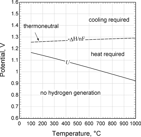
Figure 5.10 Equilibrium and thermoneutral potentials for the oxygen reaction.
In contrast to low-temperature cells, SOEC can operate in the endothermal region. Thus, these can be integrated with a waste heat source, and offer high voltage and energy efficiencies. This feature is the basis for coupling with advanced nuclear power (Fujiwara et al., Reference Fujiwara, Kasai, Yamauchi, Yamada, Makino, Matsunaga, Yoshino, Kameda, Ogawa, Momma and Hoashi2008).
In addition to affecting the faradaic efficiency, permeation of hydrogen and oxygen across the separator can reduce the purity of the products, and in some cases present a safety hazard. Because the crossover through the separator is more or less constant while the rates of oxygen and hydrogen generation are proportional to current, the purity of the products decrease at low loads. Buttler and Spliethoff (Reference Buttler and Spliethoff2018) report that the minimum load on some cells is about 25% to ensure that a flammable mixture is precluded.
5.4 Syngas and Hydrocarbons from Reduction of Carbon Dioxide
The electrochemical reduction of carbon dioxide is an active area of development (Küngas, Reference Küngas2020). A variety of C1, C2, and C3 products have been made (Kuhl et al., Reference Kuhl, Cave, Abram and Jaramillo2012). As shown in Figure 5.11, from carbon dioxide and water a variety of compounds in addition to hydrogen are possible. In terms of a liquid fuel, higher order carbons are desired. However, it may make more sense to produce CO or other one-carbon materials, as argued by Bushuyev et al. (Reference Bushuyev, De Luna, Dinh, Tao, Saur, van de Lagemaat, Kelley and Sargent2018), as building blocks. From synthesis gas for example, an assortment of materials can be produced including liquid fuels from the Fischer–Tropsch process. There are also routes from methanol to olefins. It is evident that fewer electrons are required for lower order carbon compounds, but the advantage of focusing on hydrogen and C1 compounds is that these lower order carbons are, in general, formed with higher faradaic efficiency and higher voltage efficiency.
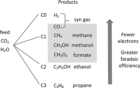
Figure 5.11 Pathways for reduction of carbon dioxide and water.
Not only is conversion of carbon dioxide from combustion sources of interest, the petrochemical industry is aggressively trying to reduce the carbon footprint from the production of ethylene, for example (Tullo, Reference Tullo2021). Ethylene has a double carbon bond that can be used in a large number of reactions – ethylene is essential for the production of PVC, polyethylene, and detergents for example. The production of ethylene from cracking requires a lot of heat, which comes from the combustion of fossil fuels, releasing large quantities of carbon dioxide, approaching 1% of the global emissions (Tullo, Reference Tullo2021). A detailed examination of this is beyond the scope, but one path to reducing the carbon footprint is the electrochemical reduction of carbon dioxide to produce ethylene directly (Khoo et al., Reference Khoo, Halim and Handoko2020; Ogura, Reference Ogura2013). Alternatively, carbon dioxide can be reduced to carbon monoxide and synthesis gas formed. There are known chemical routes to produce subsequently ethylene and other chemicals from syngas. The reactions in a high temperature oxygen ion conductor are

and

Whereas low-temperature systems (particularly acid) for the production of carbon monoxide suffer from poor faradaic efficiency, higher temperature electrolyzers can have a faradaic efficiency of 1 for the electroreduction of carbon dioxide (Küngas, Reference Küngas2020). On the other hand, it has been challenging to increase the size of individual cells for SOECs.
Bushuyev et al. (Reference Bushuyev, De Luna, Dinh, Tao, Saur, van de Lagemaat, Kelley and Sargent2018) identify three quantities that are of importance to the electrochemical reduction of carbon dioxide: the faradaic efficiency, the overpotential, and the current density. These are consistent with what we have previously discussed – the overpotential and current density are represented by the polarization curve. Because overpotential and current density are coupled, it is better to consider them together rather than separate quantities.
Present industrial use of carbon monoxide is large. A single syngas plant may produce 10,000 tonnes or more of carbon monoxide per year (Abadie and Chamorro, Reference Abadie and Chamorro2009). We consider here its productions electrochemically. Assuming operation at a current density of 10 kA/m2, the separator area can be calculated from Faraday’s law.
 (5.32)
This calculation assumes the faradaic efficiency is one, or said another way, the selectivity is one. Bushuyev et al. (Reference Bushuyev, De Luna, Dinh, Tao, Saur, van de Lagemaat, Kelley and Sargent2018) analyzed the electrochemical reduction of carbon dioxide and concluded that even with present technology the process could be economical if low-cost electricity is available.
