I. INTRODUCTION
The hydrogen permeable alloy membranes are important key materials for hydrogen purification technologies. Reference Kikuchi1–Reference Paglieri and Way5 For example, Pd–Ag or Pd–Cu alloy membranes are widely used practically for the separation and purification of hydrogen gas. Reference Paglieri and Way5 Recently, there has been a great demand for the development of new hydrogen permeable alloys to reduce the material cost as well as to improve the hydrogen permeability. Reference Dolan6–Reference Steward11 Nb-based and V-based alloys are promising materials for hydrogen permeable membrane to be substituted for currently used Pd-based alloys. This is because they are less expensive and possess higher hydrogen permeability than Pd-based alloys. Reference Buxbaum and Kinney7–Reference Steward11 However, a brittle fracture likely occurs during the operation under high pressure H2 gas atmosphere which impedes the practical use of these alloy membranes. Reference Dolan6,Reference Gahr and Birnbaum12
Recently, the mechanical properties of niobium (Nb) and vanadium (V) membranes in hydrogen gas atmosphere at high temperature have been investigated by the in situ small punch (SP) test method. Reference Matsumoto, Yukawa and Nambu13,Reference Yukawa, Nambu and Matsumoto14 It is found that a ductile-to-brittle transition occurs drastically at the hydrogen concentration around 0.2–0.25 (H/M) for both Nb and V membranes. Reference Matsumoto, Yukawa and Nambu13,Reference Yukawa, Nambu and Matsumoto14 This critical hydrogen concentration is referred to as the DBTC (the Ductile-to-Brittle Transition hydrogen Concentration). To prevent a brittle fracture of the membrane with group 5 metals such as Nb and V, the hydrogen concentration in the membrane must be controlled and kept below the DBTC, i.e., 0.2 (H/M), during the operation of hydrogen permeation.
On the other hand, the hydrogen diffusion in metal membrane is generally the rate-limiting process of the total reaction of hydrogen permeation through them. Therefore, the Fick's law is commonly applied to the metal membranes to discuss the property of them
where J is the flux of hydrogen atoms, D is the diffusion coefficient, and dc/dx is the gradient of the hydrogen concentration in the permeation direction in the metal membrane. For a membrane with the thickness of L, Eq. (1) is modified as follows.
where c 1 and c 2 are the hydrogen concentrations at feed and permeation sides of the membrane, and Δc is these difference (Δc = c 1 − c 2). In Eq. (2), the hydrogen concentration profile in the membrane is approximated by a straight line with constant slope. In addition, at low hydrogen concentration, the Sieverts' law links the hydrogen concentration, c, and the corresponding hydrogen pressure, P, as follows,
where K is the hydrogen solution coefficient. Substituting Eq. (3) into Eq. (2), the hydrogen flux, J, can be expressed as follows.
where P
1 and P
2 are the hydrogen pressure at feed and permeation sides of the membrane, and
![]() $\Delta \sqrt P$
is these difference
$\Delta \sqrt P$
is these difference
![]() $\left( {\Delta \sqrt P = \sqrt {{P_1}} - \sqrt {{P_2}} } \right)$
. ϕ is defined as the product of D and K, and widely used as a measure indicating hydrogen permeation ability of metal membranes. Here, the exponential factor of 0.5 in
$\left( {\Delta \sqrt P = \sqrt {{P_1}} - \sqrt {{P_2}} } \right)$
. ϕ is defined as the product of D and K, and widely used as a measure indicating hydrogen permeation ability of metal membranes. Here, the exponential factor of 0.5 in
![]() $\sqrt P$
comes from the splitting of molecular hydrogen into two hydrogen atoms on the surface of the membranes.
$\sqrt P$
comes from the splitting of molecular hydrogen into two hydrogen atoms on the surface of the membranes.
Following Eq. (4), the hydrogen flux changes proportional to
![]() $\Delta \sqrt P$
. However, there are many exceptional cases that the hydrogen flux does not change proportionally with
$\Delta \sqrt P$
. However, there are many exceptional cases that the hydrogen flux does not change proportionally with
![]() $\Delta \sqrt P$
.
Reference Hurlbert and Konecny15,Reference Morreale, Ciocco, Enick, Morsi, Howard, Cugini and Rothenberger16
In such cases, the exponential factor, n, in P
n
is modified from 0.5 to 0.6–0.7. However, there is no theoretical background for these factors other than 0.5. To understand these exceptional cases, Hara et al. have recently proposed a concept based on the pressure dependent hydrogen permeability.
Reference Hara, Ishitsuka, Suda, Mukaida and Haraya17–Reference Hara, Caravella, Ishitsuka, Suda, Mukaida and Haraya19
$\Delta \sqrt P$
.
Reference Hurlbert and Konecny15,Reference Morreale, Ciocco, Enick, Morsi, Howard, Cugini and Rothenberger16
In such cases, the exponential factor, n, in P
n
is modified from 0.5 to 0.6–0.7. However, there is no theoretical background for these factors other than 0.5. To understand these exceptional cases, Hara et al. have recently proposed a concept based on the pressure dependent hydrogen permeability.
Reference Hara, Ishitsuka, Suda, Mukaida and Haraya17–Reference Hara, Caravella, Ishitsuka, Suda, Mukaida and Haraya19
It is well known that the gradient of hydrogen concentration, dc/dx, is not always the driving force for hydrogen diffusion. Strictly speaking, the hydrogen diffusion is driven by the gradient of the hydrogen chemical potential, dμ/dx. Recently, present authors have proposed a new consistent description of the hydrogen permeation through metal membrane based on hydrogen chemical potential. Reference Suzuki, Yukawa, Nambu, Matsumoto and Murata20
In this paper, the new description of the hydrogen permeation is explained in detail and some examples of the application for alloy design will be reviewed.
II. NEW DESCRIPTION OF HYDROGEN PERMEATION BASED ON HYDROGEN CHEMICAL POTENTIAL
The diffusion equation based on the chemical potential is expressed as follows. Reference Fukai21
where B(c) is the mobility for hydrogen diffusion. Here, J, B, and μ are expressed as functions of each variable in parenthesis. Strictly speaking, B and μ are also functions of temperature, T, but it is omitted here because it is usually controlled to be constant during hydrogen permeation. Assuming the following three conditions, the new description of hydrogen permeation is derived (see Appendix); (i) the hydrogen permeation reaction reaches to the steady state condition [i.e., J(x) = J = const. for x], (ii) the mobility for hydrogen diffusion, B(c), is independent of the hydrogen concentration, c, [i.e., B(c) = B = const. for c] and (iii) an equilibrium condition is established between gaseous hydrogen and dissolved hydrogen atom on the metal surface of the membrane during hydrogen permeation.
where R is the gas constant and p(c) is nondimensional hydrogen pressure. Here, it is important to note that the term “d ln p(c)/dc” reflects the gradient of the pressure-composition-isotherm (PCT curve), meaning that the hydrogen flux, J, is linked directly with the shape of the PCT curve of the material. The integral term in Eq. (6) is defined as PCT factor, f PCT, because it is determined by analyzing the corresponding PCT curve. Then, Eq. (6) is simply expressed as follows.
Thus, assuming the three conditions (i)–(iii), the new description of hydrogen permeation is derived from the diffusion equation based on hydrogen chemical potential.
Similar approach has been reported by applying the idea of hydrogen chemical potential to the problem of hydrogen permeation through metal membrane. For example, Dolan et al. have analyzed the hydrogen diffusivity through V-based alloys in view of the hydrogen chemical potential.
Reference Dolan, Kellam, McLennan, Liang and Song22,Reference Dolan, McLennan and Way23
The concentration-independent diffusion coefficients,
![]() ${D^ * }$
, have been estimated from Eqs. (1) and (5) as follows.
${D^ * }$
, have been estimated from Eqs. (1) and (5) as follows.
 $$D = cB{{{\rm{d}}\mu } \over {{\rm{d}}c}} = RTBc{{{\rm{d}}\,\ln \,p{{\left( c \right)}^{{1 \mathord{\left/ {\vphantom {1 2}} \right. \kern-\nulldelimiterspace} 2}}}} \over {{\rm{d}}c}} = RTB{{{\rm{d}}\,\ln \,p{{\left( c \right)}^{{1 \mathord{\left/ {\vphantom {1 2}} \right. \kern-\nulldelimiterspace} 2}}}} \over {{\rm{d}}\,\ln \,c}} = {D^*}{f_{{\rm{therm}}}}\quad ,$$
where f therm is known as the thermodynamic factor. In their approach, D is estimated from Eq. (2) assuming a constant gradient of hydrogen concentration across the membrane. Here, it is noted that the thermodynamic factor, f therm, is the half of the integrand in the PCT factor, f PCT. In view of Eq. (8), the effects of hydrogen concentration on the hydrogen diffusivity have been discussed. However, the thermodynamic factor is determined at each hydrogen concentration, and the total hydrogen flux has not been discussed in view of the hydrogen chemical potential.
In contrast, in our approach, the term of hydrogen chemical potential is integrated across the membrane. In this case, it is not necessary to assume a linear hydrogen concentration profile across the membrane. The term of the hydrogen chemical potential expressed as the PCT factor, f PCT, is separated from the hydrogen diffusivity as shown in Eq. (7). Thus, the hydrogen permeation ability can be discussed in view of hydrogen diffusivity and the PCT factor, f PCT. Also, the new description is useful not only for understanding the property of hydrogen permeable metal membranes, but also for alloy design with high hydrogen flux and strong resistance to hydrogen embrittlement, as mentioned later.
III. VALIDITY OF THE NEW DESCRIPTION OF HYDROGEN PERMEATION
A. Experimental procedure
1. Sample preparation
A pure niobium rod of ϕ 12 mm in diameter is cut into a disk with about 0.65 mm in thickness and they are annealed in vacuum at 1253 K for 86.4 ks.
Both sides of the specimens are mechanically polished by alumina abrasive papers followed by the polishing with 1 μm diamond slurry and the final polishing with 0.05 μm alumina powders. The final thickness, L, of the specimen is 0.457 mm. Subsequently, pure palladium of about 200 nm in thickness is deposited on both sides of the sample surfaces by using an RF magnetron sputtering apparatus under 1 Pa of high purity argon gas atmosphere at 573 K. These palladium layers protect the surface from oxidation. They also act as catalyst to eliminate the impediment barrier for hydrogen dissociation and dissolution reactions on the surface.
On the other hand, a plate of Pd–27 mol% Ag alloy with thickness of 49 μm is prepared, and cut into disk with a diameter of about 12 mm. They are annealed in a high purity argon gas atmosphere at 1273 K for 10.8 ks.
2. Hydrogen permeation test
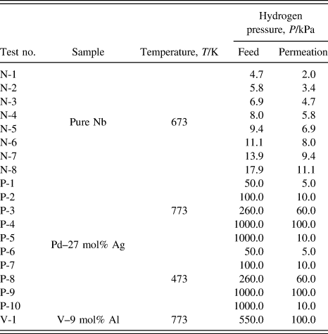
The permeation tests for pure niobium are performed at 673 K by the conventional gas permeation method with differential pressure. Reference Nambu, Shimizu, Ezaki, Yukawa and Morinaga8 The disk sample is set in a cell of hydrogen permeation test apparatus and then evacuated. Subsequently, it is heated up to 673 K and then high purity (99.99999%) hydrogen gas is introduced to both sides of the disk sample. The feed and permeation hydrogen pressures are determined from the PCT curve for pure niobium reported by Veleckis and Edwards Reference Veleckis and Edwards24 which is shown in Fig. 1. The hydrogen pressures at the feed sides are controlled so that the equilibrium hydrogen concentration increases from 0.2 (H/M) with the incremental step of 0.05 (H/M). The permeation hydrogen pressures are determined so that the difference of the hydrogen concentration, Δc, becomes a constant value of 0.1 (H/M). The testing conditions of the temperature as well as the feed and permeation hydrogen pressures applied in this study are listed in Table I. The hydrogen flux which permeates through the disk sample is measured by monitoring the pressure change of the reserve tank with known volume. The hydrogen flux is measured for each condition within about 10 min, and the entire measurement is finished within about 2 h. In this time-scale at 673 K, the degradation of the hydrogen flux due to the interdiffusion between palladium overlayer and niobium base metal is negligible. The detailed explanation of the hydrogen permeation test is given elsewhere. Reference Nambu, Shimizu, Ezaki, Yukawa and Morinaga8
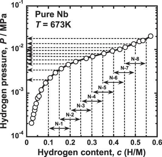
FIG. 1. Pressure-composition-isotherm (PCT curve) for pure niobium at 673 K (Ref. Reference Dolan, Kellam, McLennan, Liang and Song22) and the pressure conditions of hydrogen permeation tests.
TABLE I. Temperature and pressure conditions of hydrogen permeation tests in this study.
It is noted that the hydrogen permeation tests for pure niobium are performed successively without sample failure even under the testing condition where the hydrogen concentration exceeds the boundary of the ductile-to-brittle transition. However, a brittle fracture takes place readily during the shutting down process due to hydrogen embrittlement.
On the other hand, the hydrogen permeation tests for Pd–27 mol% Ag are performed at 473 and 773 K by the same method as mentioned above. The disk sample is set into a cell for the hydrogen permeation test apparatus and then evacuated. Subsequently, the so-called “air-treatment” is performed. Reference Mejdell, Klette, Ramachandran, Borg and Bredesen25 First, the sample cell is heated up to 773 K in vacuum condition. Then ambient pressure of air is introduced into the system and wait for 600 s. The sample cell is evacuated again and then high purity hydrogen gas is introduced into the system. A series of this oxidation and reduction process for Pd-based alloy activates the sample surface for the hydrogen permeation. The testing conditions of the temperature as well as the feed and permeation hydrogen pressures applied in this study are listed in Table I.
3. Pressure-composition-isotherm (PCT curve) measurements
The pressure-composition-isotherms (PCT curves) are measured for Pd–27 mol% Ag alloy by using a conventional Sieverts-type apparatus to investigate the hydrogen solubility. A small piece of the sample is set into a cell and activated several times prior to the measurements. The measurement temperatures are 473 and 773 K.
B. Results and discussion
1. Hydrogen permeation tests for pure niobium membrane
The correlation between the hydrogen flux, J, and the hydrogen concentration at the feed side, c 1, is shown in Fig. 2. In this study, the difference of the hydrogen concentration, Δc, is fixed to be constant value of 0.1 (H/M) under all experimental conditions. Therefore, following Eq. (2), the hydrogen flux, J, is expected to be constant. However, as shown Fig. 2, the hydrogen flux, J, changes significantly depending on the testing conditions. It first decreases with increasing the hydrogen concentration up to about 0.3 (H/M) and then increases significantly with increasing the hydrogen concentration. These results indicate that the hydrogen diffusion coefficient, D, in Eq. (1) is not independent of the hydrogen concentration. According to Eq. (1), the value of D first decreases with increasing hydrogen concentration up to about 0.3 (H/M) and then increases with increasing the hydrogen concentration. Similar dependencies of the hydrogen diffusion coefficient on the hydrogen concentration have also been reported. Reference Dolan, Kellam, McLennan, Liang and Song22,Reference Dolan, McLennan and Way23,Reference Bauer, Tretkowski and Alefeld26
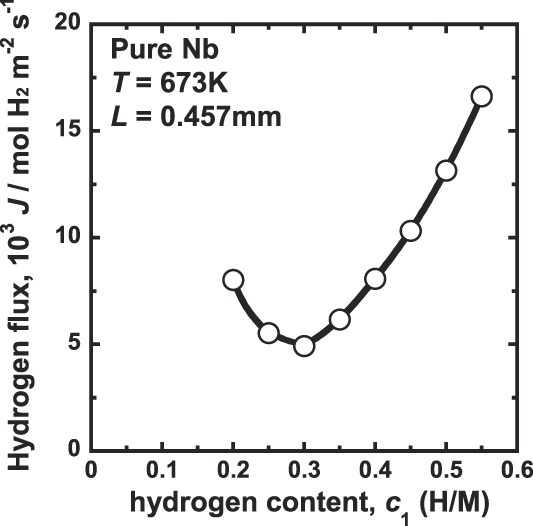
FIG. 2. Correlation between the hydrogen flux, J, and the hydrogen concentration at the inlet side, c 1 for pure niobium membrane at 673 K.
Figure 3 shows the correlation between the hydrogen flux, J, and the difference of the square root of hydrogen pressure,
![]() $\Delta \sqrt P$
. It is evident that datum are scattered and there is no linear relationship between J and
$\Delta \sqrt P$
. It is evident that datum are scattered and there is no linear relationship between J and
![]() $\Delta \sqrt P$
. Following Eq. (4), the product of the thickness of the membrane and the slope of line passing the origin and each data point,
$\Delta \sqrt P$
. Following Eq. (4), the product of the thickness of the membrane and the slope of line passing the origin and each data point,
![]() $L \times \left( {{J \mathord{\left/ {\vphantom {J {\Delta \sqrt P }}} \right. \kern-\nulldelimiterspace} {\Delta \sqrt P }}} \right)$
, corresponds to the apparent hydrogen permeation coefficient, ϕ. As shown in Fig. 3, the apparent hydrogen permeation coefficient, ϕ, changes depending on the experimental pressure condition, and cannot be determined uniquely. Thus, ϕ is not a good measure to evaluate the hydrogen permeation ability of hydrogen permeable metal membranes.
$L \times \left( {{J \mathord{\left/ {\vphantom {J {\Delta \sqrt P }}} \right. \kern-\nulldelimiterspace} {\Delta \sqrt P }}} \right)$
, corresponds to the apparent hydrogen permeation coefficient, ϕ. As shown in Fig. 3, the apparent hydrogen permeation coefficient, ϕ, changes depending on the experimental pressure condition, and cannot be determined uniquely. Thus, ϕ is not a good measure to evaluate the hydrogen permeation ability of hydrogen permeable metal membranes.
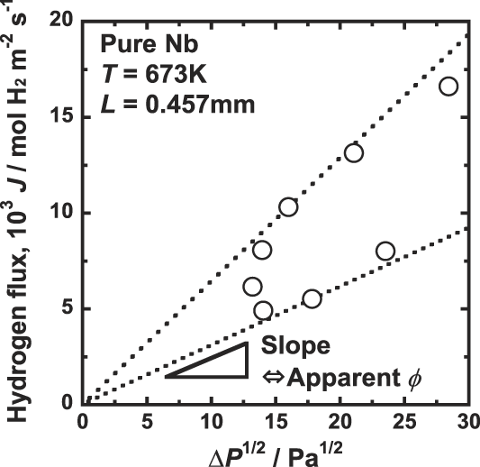
FIG. 3. Correlation between the hydrogen flux, J, and the deference of the square root of hydrogen pressure ΔP 1/2, for pure niobium membrane at 673 K.
Figure 4 shows the correlation between the hydrogen flux, J, and the PCT factor, f PCT. As shown in Fig. 4, there is a good linear relationship between J and f PCT. The line shown in Fig. 4 crosses at the origin, indicating that the hydrogen permeation reaction takes place following Eq. (7). It is noted that the slope of the line shown in Fig. 4 is RTB/2, indicating that the mobility of hydrogen atom, B, is almost constant and independent of the hydrogen concentration under the condition tested in this study. Thus, assumption (ii) is confirmed based on the experimental results.
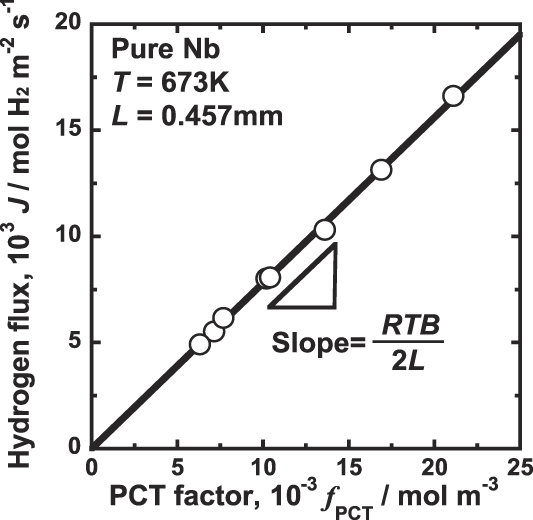
FIG. 4. Correlation between the hydrogen flux, J, and the PCT factor, f PCT, for pure niobium membrane at 673 K.
2. Factors for hydrogen diffusion
In this study of hydrogen permeation test for pure niobium, the difference of hydrogen concentration between the feed and permeation sides of the membrane is constant [Δc = 0.1 (H/M)] for each experimental condition, meaning that the integral interval of Eq. (6) is constant. Also, as mentioned above, the mobility, B, is almost constant under the experimental conditions. Therefore, the hydrogen flux, J, is expected to change with the term, c × d ln p(c)/dc. In other words, the hydrogen flux will be determined by the range of the hydrogen concentration and also by the gradient of the PCT curve.
Figure 5 shows the correlation between the gradient of the PCT curve, d ln p(c)/dc, and the hydrogen concentration, c. Comparing Fig. 2 with Fig. 5, the hydrogen concentration range below 0.3 (H/M) where J decreases with increasing in the hydrogen concentration is almost corresponds to the range where the gradient of the PCT curve significantly decreases with increasing in the hydrogen concentration. In this region, d ln p(c)/dc is dominant factor determining the hydrogen flux, J. In other words, J decreases with decreasing the driving force for hydrogen diffusion because the decrement of d ln p(c)/dc corresponds to the decrement of dμ/dc.
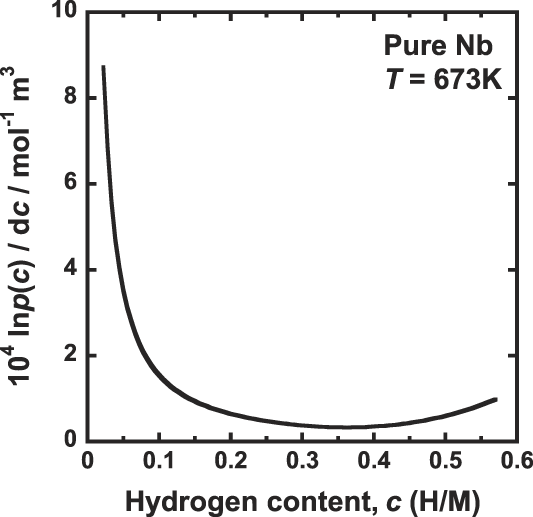
FIG. 5. Correlation between gradient of the PCT curve, d ln p(c)/dc and the hydrogen concentration, c, for pure niobium at 673 K.
The range of hydrogen concentration above 0.3 (H/M) where J increases with increasing the hydrogen concentration almost corresponds to the range where the gradient of the PCT curve is almost constant as shown in Fig. 5. Thus, the value of the term d ln p(c)/dc is almost constant and independent of the hydrogen concentration. In this case, the hydrogen concentration, c, represents the hydrogen flux, which increases with increasing the hydrogen concentration.
Thus, the hydrogen flux changes reflecting the shape of the PCT curve, which can be understood by Eq. (6). In addition, as mentioned later, the new description of hydrogen permeation is useful for alloy design of hydrogen permeable membrane.
3. Hydrogen permeation tests for Pd–Ag alloy membrane
Figure 6 shows the PCT curves for Pd–27 mol% Ag alloy measured at 473 and 773 K. As shown in this figure, the hydrogen solubility is expressed in a format of the Sieverts' law up to at least 1 MPa at 773 K. In contrast, at 473 K, the hydriding property starts to deviate from the Sieverts' law even at low hydrogen pressure.
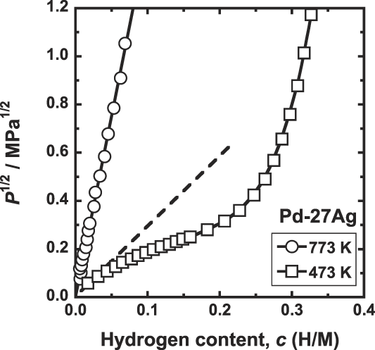
FIG. 6. PCT curves for Pd–27 mol% Ag at 473 and 773 K.
Figure 7 shows the correlation between the hydrogen flux, J, and the difference of the hydrogen concentrations at feed and permeation sides of the membrane, Δc. At high temperature such as 773 K, there is a linear relationship between J and Δc as shown in Fig. 7. However, at 473 K, it is evident that datum are scattered and there is no linear relationship.
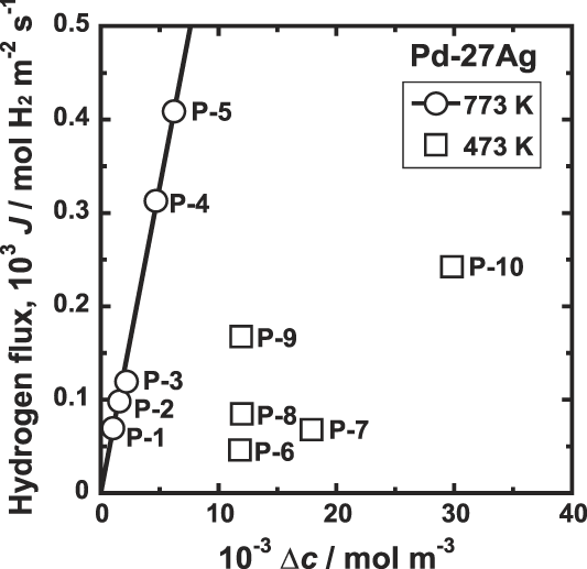
FIG. 7. Correlation between hydrogen flux, J, and the difference of the hydrogen concentrations at feed and permeation sides of the membrane, Δc, for Pd–27 mol% Ag alloy membrane at 473 and 773 K.
Figure 8 shows the correlation between the hydrogen flux, J, and the difference of the square root of the hydrogen pressures at feed and permeation sides of the membrane,
![]() $\Delta \sqrt P$
. At 773 K, there is a good linear relationship between J and
$\Delta \sqrt P$
. At 773 K, there is a good linear relationship between J and
![]() $\Delta \sqrt P$
over wide pressure range. On the other hand, at 473 K, there is linear relationship at low pressure conditions, but the data points at high pressure conditions deviate from line extrapolated from the low pressure conditions. Thus, when the hydriding property is not expressed in a format of the Sieverts' law, neither Eq. (2) nor Eq. (4) is applicable.
$\Delta \sqrt P$
over wide pressure range. On the other hand, at 473 K, there is linear relationship at low pressure conditions, but the data points at high pressure conditions deviate from line extrapolated from the low pressure conditions. Thus, when the hydriding property is not expressed in a format of the Sieverts' law, neither Eq. (2) nor Eq. (4) is applicable.
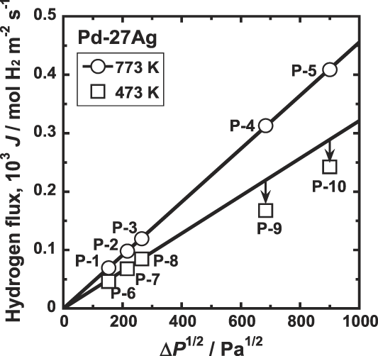
FIG. 8. Correlation between the hydrogen flux, J, and the difference of the square root of the hydrogen pressures at feed and permeation sides of the membrane, ΔP 1/2 for Pd–27 mol% Ag alloy membrane at 473 and 773 K.
On the other hand, as shown in Fig. 9, there is very good linear relationship between J and f PCT at both 773 and 473 K. Thus, the hydrogen flux is proportional to the PCT factor, f PCT, consistently regardless of whether hydrogen solubility obeys Sievert's law or not.
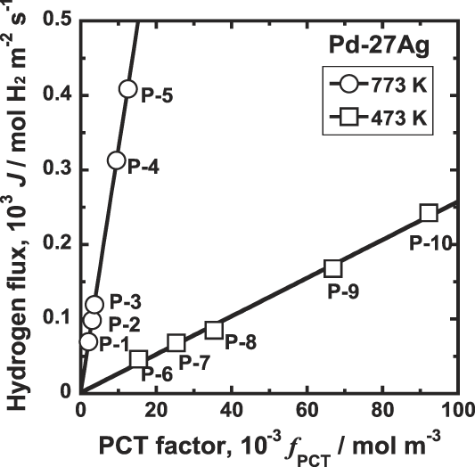
FIG. 9. Correlation between the hydrogen flux, J, and the PCT factor, f PCT, for Pd–27 mol% Ag alloy membrane at 473 and 773 K.
4. Correlation between conventional description and new description of hydrogen permeation
In this section, the reason will be discussed why the conventional descriptions of hydrogen permeation, Eqs. (2) and (4), cannot be applicable consistently. Figure 10 shows the correlation between the square root of the hydrogen pressure,
![]() $\sqrt P$
, and the hydrogen concentration, c, for pure niobium at 673 K reproduced from Fig. 1. As shown in Fig. 10, the hydriding property deviates from the Sieverts' law under the pressure conditions in this study. Also, as shown in Fig. 6, the hydriding property for Pd–27 mol% Ag at 473 K is not expressed in format of the Sievert's law under the pressure conditions for hydrogen permeation tests. Therefore, it is natural that Eq. (4) based on the Sieverts' law is not fulfilled as shown in Figs. 3 and 8.
$\sqrt P$
, and the hydrogen concentration, c, for pure niobium at 673 K reproduced from Fig. 1. As shown in Fig. 10, the hydriding property deviates from the Sieverts' law under the pressure conditions in this study. Also, as shown in Fig. 6, the hydriding property for Pd–27 mol% Ag at 473 K is not expressed in format of the Sievert's law under the pressure conditions for hydrogen permeation tests. Therefore, it is natural that Eq. (4) based on the Sieverts' law is not fulfilled as shown in Figs. 3 and 8.

FIG. 10. Correlation between the square root of hydrogen pressure, P 0.5 and hydrogen concentration, c, reproduced by Fig. 1.
On the other hand, when the hydriding property is expressed in a format of the Sieverts' law, Eq. (3) can be modified as follows.
Then, the PCT factor, f PCT, is expressed as follows.
Substituting Eq. (10) into Eq. (7), the following equation equivalent to Eq. (2) is obtained.
Thus, Eq. (2) is also derived based on the Sieverts' law, and is no longer applicable under the conditions in this study for pure niobium at 673 K and Pd–27 mol% Ag at 473 K.
IV. ALLOY DESIGN BASED ON NEW DESCRIPTION OF HYDROGEN PERMEATION
A. Concept for alloy design to obtain high hydrogen flux
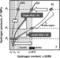
As mentioned above, the hydrogen flux, J, is proportional to the PCT factor, f PCT, meaning that increasing f PCT leads to enhanced hydrogen flux. The f PCT becomes large when the following three factors become large, (i) the integral interval (c 1–c 2), (ii) the hydrogen concentration, c, and (iii) the gradient of the PCT curve, d ln p(c)/dc, in Eq. (4). However, as mentioned before, in case of group 5 metals and its alloys, the hydrogen concentration in the membrane must be controlled and kept below 0.2 (H/M) during the operation of hydrogen permeation in view of the ductile-to-brittle transition hydrogen concentration, DBTC. From these two points of f PCT and DBTC, Suzuki et al. have proposed the most practical way to design alloy composition with high hydrogen flux while preventing brittle fracture during the operation. Reference Suzuki, Yukawa, Nambu, Matsumoto and Murata20,Reference Suzuki, Yukawa, Ijiri, Nambu, Matsumoto and Murata27,Reference Suzuki, Yukawa, Nambu, Matsumoto and Murata28 A schematic illustration showing the concept for alloy design is shown in Fig. 11. There are three PCT curves at the temperature, T. The hydrogen pressures at feed and permeation sides are fixed to be P 1 and P 2, respectively. Then, for the membrane having the PCT curve (i), high hydrogen concentration region can be used and also a large integral interval can be obtained. But the hydrogen concentration at the feed side exceeds largely the boundary of the ductile-to-brittle transition by applying P 1 pressure, and the membrane becomes brittle as shown in Fig. 11. There are two ways to reduce the hydrogen concentration to prevent brittle failure of the membrane. One is to reduce the hydrogen pressure at feed side to P 1′. The other way is to shift the PCT curve toward upper and left region, in some way, for example by alloying with an element which has lower affinity for hydrogen than the base metal. Then, for the membrane which has the PCT curve (ii), the gradient of the PCT curve, d ln p(c)/dc, is much steeper than the curve (i) while controlling the hydrogen concentration below 0.2 (H/M) even applying the same hydrogen pressure, P 1. Also, the integral interval for the PCT curve (ii) under P 1 and P 2 pressure condition becomes larger than that for the PCT curve (i) under P 1′ and P 2 pressure condition. In such case, the PCT factor, f PCT, is expected to be larger than that for the curve (i) at reduced P 1′ pressure condition. However, when the PCT curve is shifted excessively to upper and left region like PCT curve (iii), the hydrogen concentration, c, and the integral interval (c 1′–c 2′) become small and f PCT is expected to become small with fixed P 1 pressure. Thus, controlling the hydriding property of the alloy appropriately like PCT curve (ii), the hydrogen concentration range below 0.2 (H/M) can be effectively utilized. Therefore, the alloy composition must be designed to control appropriate hydriding properties under the given pressure and temperature conditions. In this study, this concept for alloy design is applied to V–Al binary system.
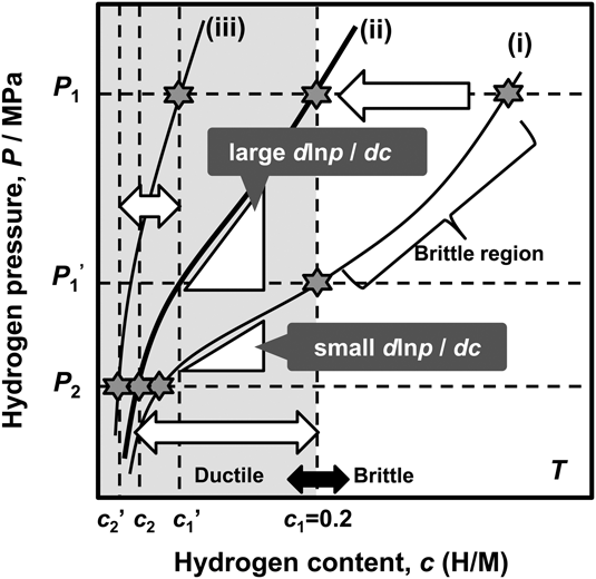
FIG. 11. Schematic illustration of the concept of alloy design based on PCT curve.
B. Design of V–Al hydrogen permeable alloy
1. Experimental procedure
a. Sample preparation
V–5 mol% Al, V–9 mol% Al, V–16 mol% Al, and V–20 mol% Al alloys are melted by using a tri-arc furnace in a purified argon gas atmosphere. The raw materials used in this study are 99.9 mass% for vanadium and 99.999 mass% for aluminum. According to V–Al equilibrium phase diagram, Reference Gong, Du, Huang, Schmid Fetzer, Zhang and Xu29 all these alloys are composed of a single solid solution phase with simple bcc crystal structure.
For hydrogen permeation test, the as-cast ingot of V–9 mol% Al is cut into disk with about 12 mm in diameter and 0.65 mm in thickness by using a wire-cut electrical discharge machine. Both sides of the specimen are mechanically polished by alumina abrasive papers followed by the polishing with 9 and 1 μm diamond slurry. The final thickness, L, of the specimen is 0.541 mm. Subsequently, pure palladium of about 200 nm in thickness is deposited at 573 K on both sides of the sample surfaces by using an RF magnetron sputtering apparatus.
b. Pressure-composition-isotherm measurements
The pressure-composition-isotherms (PCT curves) are measured at 773 K for V–5 mol% Al, V–9 mol% Al, V–16 mol% Al, and V–20 mol% Al alloys by the same procedure mentioned before. A small piece of each sample is set into a cell and activated several times prior to the measurements.
c. Hydrogen permeation tests
The hydrogen permeation tests for V–9 mol% Al are performed at 773 K by almost the same method mentioned in Sec. III. A. ii. The hydrogen flux, J, which permeates through the disk sample is measured by using a mass flowmeter. The pressure conditions at the feed and permeation sides of the membrane, P 1 and P 2, are fixed to be 0.55 MPa and 0.10 MPa, respectively.
Under the steady-state diffusion-limiting condition, J is proportional to 1/L for each metal or alloy membrane at the same temperature and pressure condition expressed in Eq. (2) or Eq. (4). Therefore, J·L is independent of the membrane thickness, L, and the hydrogen permeation property of the samples with different thickness can be compared. It is noted here that the atomic hydrogen flux, mol H/(m s) is evaluated in this study, which is twice as large as the gaseous hydrogen flux, mol H2/(m s).
2. Results and discussion
As an example of alloy design, the hydrogen permeation condition is set to be as follows. The operating temperature is 773 K, the hydrogen pressure at feed and permeation side is set to be 0.55 MPa and 0.10 MPa, respectively. Figure 12 shows the PCT curves for pure V Reference Dolan, Kellam, McLennan, Liang and Song22 and V–Al binary alloys. As shown in this figure, for pure V and V–5 mol% Al alloy, the hydrogen concentration exceeds the boundary of the ductile-to-brittle transition concentration, i.e., 0.2 (H/M), under the given condition. Therefore the hydrogen pressures at the feed side need to be reduced to 0.21 MPa for pure V and 0.30 MPa for V–5 mol% Al alloy, respectively. On the other hand, for V–16 mol% Al and V–20 mol% Al alloys, the PCT curves are shifted excessively toward left and upper region. The PCT curve for V–9 mol% Al alloy shown in Fig. 12 corresponds to the PCT curve (ii) shown in Fig. 11 and is appropriate under this condition. The PCT factor, f PCT, for each alloy at each condition represented by star symbols in Fig. 12 is estimated and the results are shown in Fig. 13. V–9 mol% Al alloy has the largest f PCT and seems the optimal composition among these alloys for the condition applied.

FIG. 12. PCT curves for pure V, Reference Dolan, Kellam, McLennan, Liang and Song22 V–5 mol% Al, V–9 mol% Al, V–16 mol% Al and V–20 mol% Al at 773 K.

FIG. 13. Estimated PCT factor for each alloy at each condition represented by star symbols in Fig. 12.
Then, the hydrogen permeation test for V–9 mol% Al alloy membrane has been performed. Figure 14 shows the time dependence of the normalized hydrogen flux, J·L for V–9 mol% Al. For comparison, the J L value for Pd–27 mol% Ag at the same condition estimated from Figs. 6 and 9 is indicated in figure. As shown in Fig. 14, the normalized hydrogen flux, J·L, for V–9 mol% Al is about 4.5 times higher than that for Pd–27 mol% Ag. When the membrane thickness of V–9 mol% Al alloy is 50 μm (i.e., almost the same thickness with Pd–27 mol% Ag alloy membrane used in this study), the hydrogen flux, J, in this condition is estimated to be about 120 mL/(cm2 min). On the other hand, as shown in Fig. 8 (test no. P-4), even applying 1 MPa of hydrogen pressure to the feed side, the J·L value for Pd–27 mol% Ag alloy membrane is about 30 × 10−6 mol H/(m s) at most. Thus, the J·L value for V–9 mol% Al alloy membrane shown in Fig. 14 [i.e., about 90 × 10−6 mol H/(m s)] is sufficiently large.

FIG. 14. Time dependence of the normalized hydrogen flux, J·L for V–9 mol% Al. The value of Pd–27Ag is also predicted for comparison.
On the other hand, as shown in Fig. 14, the J·L value for V–9 mol% Al alloy decreases gradually with time. It is considered that this decrement may be caused by the interdiffusion of V into Pd overlayer to form intermetallic compounds such as Pd3V and Pd2V at high temperature. Similar phenomenon is observed by cross-section TEM observation for Pd-coated niobium (Nb) membrane heat treated at 773 K, where Nb diffuses into Pd layer and intermetallic compounds of Pd3Nb is formed at the interface. Reference Sasaki, Hattori, Tsuchimoto, Yukawa, Arai, Tokunaga, Murata and Yamamoto30,Reference Smith and Massalski31
After the hydrogen permeation test, gas leak check is performed with helium. A photo image of the sample of V–9 mol% Al alloy after the hydrogen permeation test is shown in Fig. 15. There is no evidence of cracking on the sample due to hydrogen embrittlement. Thus, V–9 mol% Al alloy designed by the concept shown in Fig. 11 exhibits excellent hydrogen permeability with strong resistance to hydrogen embrittlement.

FIG. 15. Photo image of a disk sample of V–9 mol% Al alloy evacuated and cooled down to room temperature after hydrogen permeation test.
It is important to note that the optimal composition of non Pd-based alloy membrane changes depending on the temperature and pressure condition, and should be determined by the corresponding PCT curve. Therefore, the hydriding property of the alloy is very important to understand the hydrogen permeability of alloy membranes.
It is also important to note that when the alloy composition is determined first, the optimal condition of hydrogen pressure and temperature can be proposed following the new consistent description of hydrogen permeation.
V. SUMMARY
The new description of hydrogen permeation has been explained in detail. The hydrogen flux through metal membrane cannot be explained consistently by both the difference of the hydrogen concentration, Δc, and that of the square root of hydrogen pressure,
![]() $\Delta \sqrt P$
, when the hydriding property is not expressed in a format of the Sieverts' law. On the other hand, the hydrogen flux is proportional to the PCT factor, f
PCT, consistently. Thus, the new description of hydrogen permeation is useful for the correct understanding of the hydrogen permeation property of metals and alloys. Also, the concept for alloy design of hydrogen permeable alloy with high hydrogen flux and strong resistance to hydrogen embrittlement have been proposed in view of the PCT factor, f
PCT, and the ductile-to-brittle transition hydrogen concentration. It is demonstrated that the designed V–Al alloy membrane exhibits excellent hydrogen permeability with strong resistance to hydrogen embrittlement at a given temperature and pressure conditions.
$\Delta \sqrt P$
, when the hydriding property is not expressed in a format of the Sieverts' law. On the other hand, the hydrogen flux is proportional to the PCT factor, f
PCT, consistently. Thus, the new description of hydrogen permeation is useful for the correct understanding of the hydrogen permeation property of metals and alloys. Also, the concept for alloy design of hydrogen permeable alloy with high hydrogen flux and strong resistance to hydrogen embrittlement have been proposed in view of the PCT factor, f
PCT, and the ductile-to-brittle transition hydrogen concentration. It is demonstrated that the designed V–Al alloy membrane exhibits excellent hydrogen permeability with strong resistance to hydrogen embrittlement at a given temperature and pressure conditions.
ACKNOWLEDGMENT
This research was supported in part by CREST project from Japan Science and Technology Agency (JST) and Grant-in-Aid for Scientific Research from Japan Society for the Promotion of Science (JSPS).
APPENDIX
In this section, the derivation of Eq. (6) from Eq. (5) is explained in detail. Applied to the membrane with thickness of L, Eq. (5) can be modified as follows.
Assuming that the hydrogen permeation reaction reaches to the steady state condition [assumption (i)], the hydrogen flux, J(x), is independent of the position of the permeation direction in the membrane, x, [J(x) = J = const. for x] and the following equation is obtained.
provided that the mobility for hydrogen diffusion, B(c), is independent of the hydrogen concentration, c, [assumption (ii)] [B(c) = B = const. for c], Eq. (A-2) is modified as follows.
here, the term, dμ(c)/dc, can be obtained from the equilibrium condition of the gaseous hydrogen with the hydrogen atom in metal, i.e., pressure-composition-isotherm (PCT curve). PCT curve in the hydrogen solid solution region reflects the following equilibrium reaction.
where H α and H 2 express the dissolved hydrogen atom in the metal-hydrogen solid solution and gaseous hydrogen molecule. Eq. (A-4) can be expressed as follows.
 $$\mu \left( c \right) = {1 \over 2}{\mu _{\rm{g}}} = {1 \over 2}\left\{ {\mu _{\rm{g}}^0 + RT\,\ln \left( {{{P\left( c \right)} \over {P{}^0}}} \right)} \right\} = {1 \over 2}\left\{ {\mu _{\rm{g}}^0 + RT\,\ln \,p\left( c \right)} \right\}\quad ,$$
where
![]() ${\mu _{\rm{g}}}$
and
${\mu _{\rm{g}}}$
and
![]() $\mu _{\rm{g}}^0$
are the chemical potential and standard chemical potential of gaseous hydrogen, P(c) is the equilibrium hydrogen pressure, P
0 is standard hydrogen pressure (101,325 Pa) and p(c) is nondimensional pressure [p(c) = P(c)/P
0]. Applying Eq. (A-5) into Eq. (A-3), Eq. (6) is obtained.
$\mu _{\rm{g}}^0$
are the chemical potential and standard chemical potential of gaseous hydrogen, P(c) is the equilibrium hydrogen pressure, P
0 is standard hydrogen pressure (101,325 Pa) and p(c) is nondimensional pressure [p(c) = P(c)/P
0]. Applying Eq. (A-5) into Eq. (A-3), Eq. (6) is obtained.
To estimate the value of f PCT, the PCT curve is analyzed based on the following regression function.
where m i is the regression coefficient. The first and second terms in the right side in Eq. (A-6) expresses the Sieverts' law in dilute hydrogen concentration region. The deviation from the Sieverts' law in large hydrogen concentration region is approximated by polynomial function in the third term. Then, the PCT factor, f PCT, is expressed as follows.
 $${f_{{\rm{PCT}}}} =\, \int_{{c_2}}^{{c_1}} {c{{{\rm{d}}\,\ln \,p\left( c \right)} \over {{\rm{d}}c}}} {\rm{d}}c = 2\left( {{c_1} - {c_2}} \right) + \sum\limits_{i = 1} {{i \over {i + 1}}{m_i}\left( {c_1^{i + 1} - c_2^{i + 1}} \right)} \quad .$$
The values of c 1 and c 2 are estimated by the following equation based on Eq. (A-6) and the pressure conditions, P 1 and P 2.
Then, it is necessary to assume that an equilibrium condition is established between gaseous hydrogen and dissolved hydrogen atom on the metal surface of the membrane during hydrogen permeation [assumption (iii)].


