Introduction
The advancement of low-power wireless communication technology in the past couple of decades enabled its utilization in many applications as personal electronics. Personal medical devices are one of the pioneer beneficiaries of their usage. Upon the recommendation of ITU-R in 1999, FCC allocated 402–405 MHz as the Medical Implant Communication Service band in 2001 for the indoor wireless link of medical devices used in diagnostic and therapeutic operations [Reference Savci, Sula, Wang, Dogan and Arvas1]. Since then, numerous implantable, in-vitro and wearable medical devices such as cardiac pacemakers, endoscopic camera capsules, cochlear implants, and neuro-stimulators have utilized this band for wireless communication. In addition, semiconductor companies such as Microsemi (back then Zarlink) developed commercially available CMOS-integrated transceivers for both implant modules (ZL70323MNJ) and base station modules (ZL70123MNG7) tailored for MICS applications only. These systems use different antennas, depending on the specific application [Reference Basmer, Todtenberg, Popiella and Birkholz2]. MICS base stations generally use helical antennas while the implants incorporate printed antennas such as a meandered planar inverted-F antenna [Reference Lee, Seo and Lee3], an L-shaped T-line-fed anti-spiral resonator [Reference Palandoken4], and a commercially available grounded-line technique-based Splatch by antenna factor [5].
Over the years, the increased application complexity, the push for smaller and faster devices, and the addition of more wireless nodes required allocating broader frequency bandwidth and forming a standard. In 2012, FCC allocated 40 MHz of spectrum at 2360–2400 MHz band to medical wireless body area networks (WBANs) as a secondary basis user for short-range indoor low-power wireless links. IEEE 802.15.6 communication standard is established for these body area network devices and can operate with data rates up to 10 Mbps [6].
Besides the medical purpose [Reference Sabban7], the wearable body area network devices found applications in many areas such as mobile communications [Reference Rogier, Agneessens, Castel, Lemey, Declercq, Vanveerdeghem, Van Torre, Vallozzi and Joseph8] and military [Reference Lee, Tak and Choi9]. With the introduction of IEEE 802.15.6 in 2012, body-worn WBAN devices such as Google Glass, GoPro cameras, and Nike+ sensor became part of daily life for various applications ranging from remote health monitoring to outdoor sports activity. Such devices utilize antennas strapped or placed on the user, and having an efficient antenna is critical for system performance. Depending on the applications, these systems may require antennas in different shapes, forms, and materials. For example, printing the antenna on textile clothes became a preferred method for most wearable electronics. These antennas must be flexible, low-cost, lightweight, and easy to implement on clothes.
During the fight against the globally spread pandemic COVID-19 disease in the first half of 2020, we, the engineers and medical professionals were seeking the best solution for remote connected and disposable medical sensors. The low-cost wearable wireless medical devices are a good fit for such purposes. Many of these devices do employ printed antennas on textiles for wireless connection. These wearable antennas are usually placed near the human head, torso, or arm. The antenna's performance is greatly affected by the presence of lossy human tissues inside the antenna's near-field region. In addition to the degradation of antenna performance, the electromagnetic (EM) radiations from the antennas may produce a detrimental effect on the human body [Reference Hardell and Sage10]. Because many wearable antennas are used for therapeutic, diagnostic, or healthy lifestyle purposes, they are expected not to pose any discomfort to the users. Therefore, it is vital to keep the rate of EM energy absorbed by human tissues below a certain level. This rate is defined as the specific absorption rate (SAR), which must be less than 1.6 W/kg [Reference Ulcek and Cleveland11] for 1-g of tissues and 2 W/kg [12] for 10-g of tissues.
The SAR distribution in the human head due to EM energy radiated by an adjacent cellular phone having different types of antennas has been studied extensively using the finite-difference time-domain (FDTD) method in [Reference Wang and Fujiwara13–Reference Geyikolu, Kaburcuk and Çavusolu23]. In [Reference Salonen, Rahmat-Samii and Kivikoski24–Reference Le and Yun34], the SAR distribution on the part of human body phantom due to a wearable textile antenna has been studied using commercial software tools. In this work, the SAR calculations are performed on a realistic human-head model instead of a rough human body model using our in-house developed custom FDTD Matlab codes [Reference Elsherbeni and Demir35]. The interaction between a human-head model and a wearable textile antenna has never been evaluated because the FDTD method requires excessively long computation times and large memory requirements when the FDTD cell size is in the order of 0.05 of the wavelength in the tissue. This study utilizes a high-performance computing system to investigate the interaction between a wearable textile antenna and a realistic human-head model with a cell size of 0.5 mm.
In this paper, an M-shaped dual-resonance wearable antenna is designed using the FDTD method and fabricated on a thick textile mat: a skin cap. The fabricated dual-band wearable antenna operates at the WBAN band and 5.8 GHz ISM band, achieving the bandwidth requirements of 40 and 150 MHz, respectively. The antenna performance is evaluated based on two primary performance metrics: the radiation pattern and the input reflection coefficient. These evaluations are done with and without a human-head model. The effect of the EM energy radiated by the wearable antenna based on the SAR distribution in a realistic human-head model is investigated numerically using the in-house developed Matlab codes based on the FDTD method.
Method and models
FDTD method
The FDTD method [Reference Elsherbeni and Demir35] is one of the most powerful and widely used methods for bio-EM applications due to its ability to handle complex and heterogeneous geometries and provide solutions over a wide band. The FDTD method solves Maxwell's equations in the time domain and calculates the model's six vector components of electric and magnetic fields in each cubic cell. The major constraint [Reference Elsherbeni and Demir35] in the FDTD method is the cell size, which must be 20 times smaller than the smallest wavelength in the model. Finally, the convolution perfect matching layer (CPML) [Reference Roden and Gedney36] is applied as an absorbing boundary to truncate the problem domain. In this work, a custom FDTD code is developed to analyze the EM interaction between the realistic human-head model and the designed wearable antenna on a beret cap.
M-shaped wearable antenna on a textile substrate
The top and bottom views of the M-shaped antenna with all dimensions are shown in Fig. 1. A partial ground backs the M-shaped driven element on the bottom of the textile material with a slot. The antenna designed using the FDTD method is fabricated on a 2 mm thick textile substrate of dielectric constant $\epsilon _r = 1.54$![]() with negligible loss. The photograph of the fabricated M-shaped antenna on a beret cap is shown in Fig. 1. The simulation and measurement input reflection coefficients (S 11) of the wearable antenna are shown in Fig. 2. It can be seen from the plot that the dual-band resonant frequencies showed a good agreement between the simulation and measurement.
with negligible loss. The photograph of the fabricated M-shaped antenna on a beret cap is shown in Fig. 1. The simulation and measurement input reflection coefficients (S 11) of the wearable antenna are shown in Fig. 2. It can be seen from the plot that the dual-band resonant frequencies showed a good agreement between the simulation and measurement.

Fig. 1. (a) Top and (b) bottom views of the M-shaped wearable antenna with all dimensions, and (c) the fabricated wearable antenna on a flat top textile beret model.
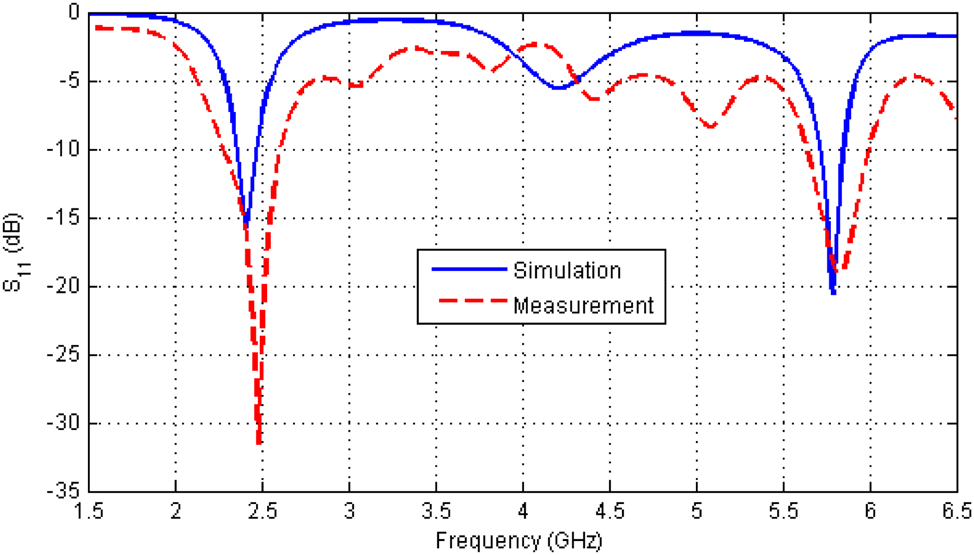
Fig. 2. Simulated and measured S 11 of the antenna on a textile substrate.
Human-head model
A realistic human-head model proposed in [Reference Zubal, Harrell, Smith, Rattner, Gindi and Hoffer37] is used in this work. The dimensions of the head model are 172 × 218 × 240 mm3. The head model is divided into 73 million cells whose sizes in all directions are 0.5 mm. Thus, the total cell number of the FDTD problem space with 10 CPML cells and 10 air gap cells on all sides is about 100 million.
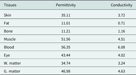
The head model consists of eight tissues: skin, fat, bone, eye, blood vessel, muscle, white matter, and gray matter. The mass density [Reference Kaburcuk and Elsherbeni20], relative permittivity, and conductivity of the head tissues calculated from Debye coefficients in [Reference Kaburcuk and Elsherbeni20] and [Reference Eleiwa and Elsherbeni38] for 2.4 and 5.8 GHz are tabulated in Tables 1 and 2. Figure 3 shows the human-head model's x–y, x–z, and y–z cross sections.
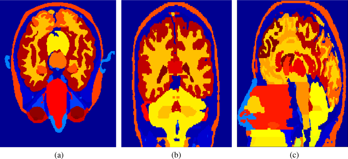
Fig. 3. (a) x–y, (b) x–z, (c) and y–z cross-sections of the human-head model.
Table 1. Mass density, relative permittivity, and conductivity of the head tissues for 2.4 GHz
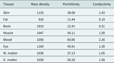
Table 2. Relative permittivity and conductivity of the head tissues for 5.8 GHz
SAR calculation
The EM energy absorbed by biological tissues is quantified as SAR. The SAR is defined as
where E is the root-mean-square magnitude of the electric field strength in V/m, σ is the conductivity of tissue, ρ is the mass density of the tissue, and r denotes the indexed cell. The IEEE standard C95.3-2002 [39] is used to calculate the SAR distributions over 1-g of tissue (SAR1g) and 10-g of tissue (SAR10g) in the human head model. The input power of the antenna for 2.4 and 5.8 GHz is set to 20 dBm, which is the maximum power of wireless local area networks (WLANs). The assumption of being exposed to such a power rating is realistic when the co-existence of WLAN and WBAN in a medical environment is considered.
Numerical results
This section investigates the effects of the human-head model on the input reflection coefficient and the wearable antenna's radiation patterns. Then, the EM effect of the wearable antenna fabricated on the beret cap to the human-head model is investigated at 2.4 and 5.8 GHz by using the FDTD numerical solution. The SAR1g and SAR10g distributions in the human-head model due to the wearable antenna are calculated at each frequency of interest. The FDTD numerical problem is constructed with the antenna printed on a textile beret model placed 12 mm above the human-head model. Matlab-based custom-developed FDTD codes are used in this study. The simulations are done in the 2018 64-bit Matlab version running on a 32-core high-power computing system with 512 GB RAM. The computation time for the entire EM analysis and the SAR calculations is roughly 12 000 min. The solution is done without any simplification and mesh optimization. The CPU-based numerical solution for such a big problem would be incredibly long on a standard workstation. For such reason, this study would be a reference for simplified solutions.
Effect of human-head model on the antenna performance
The simulations are done with a realistic human-head model, and the measurements are taken while the beret cap is placed on a human head. The superimposed plot having both the simulated and measured input reflection coefficients is shown in Fig. 4. It can be seen from the plot that the simulated and measured performances match pretty well. Our FDTD algorithm is only coded for the use case of a flat antenna substrate and does not cover the case for bent structures. Therefore it is essential to keep the antenna structure flat. The textile material is reinforced from the perimeter of the top surface of the cap to keep the antenna printed region flat while it is worn. The slight deviations in the measured performance are due to the variation in the electrical properties of textile material and fabrication tolerances. Figure 5 shows the photograph taken during the measurements while the textile beret with antenna was worn. The radiation patterns of the wearable antenna with and without the human-head model at resonance frequencies obtained using the FDTD method are shown in Fig. 6. The maximum gain (dBi) and efficiency (%) values of the antenna with and without the head model are tabulated in Table 3.
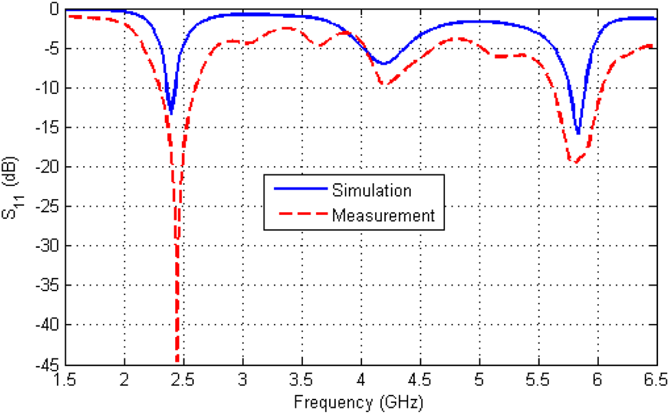
Fig. 4. Simulated and measured S 11 of the wearable antenna with the human-head model.

Fig. 5. Photograph of the wearable antenna with a real human head.
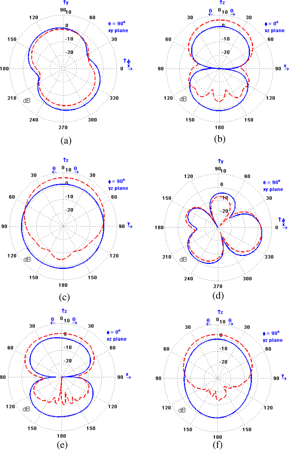
Fig. 6. Radiation patterns of the wearable antenna with and without human-head model on the (a) the x–y, (b) the x–z, and (c) the y–z plane cuts for 2.4 GHz and (d) the x–y, (e) the x–z, and (f) the y–z plane cuts for 5.8 GHz (blue curves: only antenna; red dashed curves: head with the antenna).
Table 3. Maximum gain (gain) and efficiency (eff.) of the antenna with and without the head at 2.4 and 5.8 GHz

SAR1g and SAR10g distributions in the human head due to the wearable antenna
The SAR1g and SAR10g distributions in the x–y, x–z, and y–z cross sections of the human head model are shown for 2.4 and 5.8 GHz in Figs 7 and 8, respectively. The maximum values of SAR1g and SAR10g at resonance frequencies are tabulated in Table 4. The SAR1g and SAR10g values reported in Table 4, except the value at 2.4 GHz, are less than 1.6 W/kg [Reference Ulcek and Cleveland11] for 1-g of tissues and 2 W/kg [12] for 10-g of tissue, respectively. At 2.4 GHz, the maximum SAR1g value just above 1.6 W/kg is within an acceptable range according to the studies in the literature. It can be seen from Figs 7 and 8 that the maximum SAR values occur on the top of the human head due to the wearable antenna on the flat top textile beret. It is also realized from these figures the SAR1g and SAR10g distributions appear in a good correlation. It can be realized that the resonance frequencies affect the maximum SAR1g and SAR10g values and SAR distributions.

Fig. 7. (a1), (a2), (a3) SAR1g and (b1), (b2), (b3) SAR10g (W/kg) distributions on the x–y, x–z, and y–z cross sections of the human-head model for 2.4 GHz.
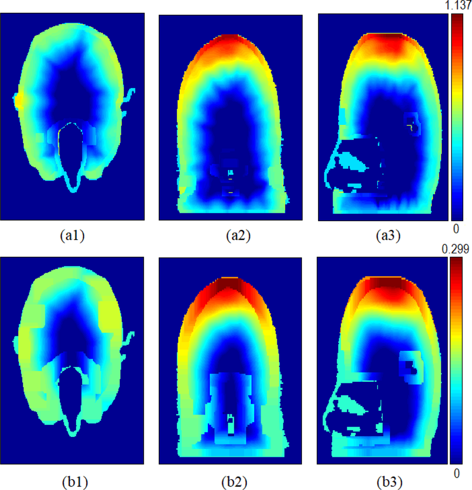
Fig. 8. (a1), (a2), (a3) SAR1g and (b1), (b2), (b3) SAR10g (W/kg) distributions on the x–y, x–z, and y–z cross sections of the human-head model for 5.8 GHz.
Table 4. Maximum SAR1g and SAR10g at 2.4 and 5.8 GHz

Calculation of the SAR distributions on the human body parts due to a wearable textile antenna by using commercial software tools is the prime topic of antenna research [Reference Salonen, Rahmat-Samii and Kivikoski24–Reference Le and Yun34] in recent years. A fair comparison of the obtained results is difficult because the SAR distributions and maximum SAR values depend on antenna types, substrates, input power, resonance frequencies, and distance between the antenna and the human body phantom.
Textile antennas on the human body model have been reported in [Reference Yan, Soh and Vandenbosch28, Reference Joshi, Hussin, Soh, Jamlos, Lago, Al-Hadi and Podilchak32, Reference Ashyap, Abidin, Dahlan, Abdul Majid, Shah, Kamarudin and Alomainy40–Reference Zhang, Vandenbosch and Yan44]. Tables 5 and 6 summarize the existing studies regarding design features (substrate type and thickness, location on the human body model, and phantom model) and performance metrics (antenna resonance frequencies, gain, input power, SAR1g, and SAR10g values), respectively. The tables show that the antenna's properties, input power, and phantom model affect the maximum SAR values.
Table 5. Design features of some recent studies in the literature
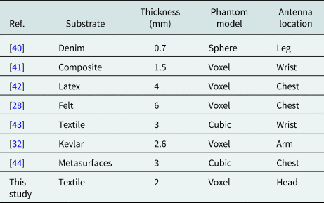
Table 6. Performance comparison of some recent studies in the literature

Conclusion
The need for remote health operations is increased tremendously over the last 2 years due to the global spread of pandemic diseases. The low-cost wearable RF devices find wide usage for diagnostic and therapeutic purposes. In such cases, it would be a significant question to answer if the wearable devices pose any discomfort or health risk to the patients. In this study, the interactions between a realistic human-head model and RF EM fields radiated by a wearable antenna were evaluated using the FDTD method at WBAN and WLAN frequencies. A custom M-shaped antenna is designed on a beret made out of textiles. The fabric is characterized as a 2 mm thick substrate. The antenna is manufactured and measured in our RF lab. The simulation and measurement results show a good agreement. Then, the effect of the wearable antenna, the SAR1g, and SAR10g distributions on the human head are calculated using the FDTD method. Based on this study, it is concluded that even under maximum WLAN power settings, the SAR ratings of the wearable antenna designed for this study are still under the IEEE maximum RF exposure limits.
Conflict of interest
None.
 Hüseyin Şerif Savcı received a BS in Electronics & Communication Engineering from Yildiz Technical University, Istanbul, Turkey, in 2001 and his MS and Ph.D. degrees in Electrical Engineering from Syracuse University, Syracuse, NY, USA, in 2005 and 2008, respectively. His dissertation on low CMOS receiver for medical implant devices was awarded the Syracuse University 2009 best thesis award. From 2008 to 2013, he was with Skyworks Solutions Inc., Cedar Rapids, IA, USA, as a senior RFIC design engineer. Between 2013 and 2020, he worked for Hittite Microwave Corporation, Chelmsford, Massachusetts, and Analog Devices Inc., Istanbul, Turkey, as a principal design engineer, where he designed many RFIC and MMIC products on SOI, GaN, and GaAs technologies for test and measurement, microwave/mm-wave cellular infrastructure, and ADEF applications. In 2020, he joined the Department of Electrical and Electronics Engineering at Istanbul Medipol University, Istanbul, Turkey, as an assistant professor. His research interests include designing and modeling RF and microwave integrated circuits, devices, systems, and antennas. He is serving as an associate editor for the Applied Computational Electromagnetics Society (ACES) Journal.
 Fatih Kaburcuk received his MS and Ph.D. degrees in Electrical Engineering from Syracuse University, Syracuse, NY, USA, in 2011 and 2014, respectively. During his graduate studies, he worked as a research assistant with Syracuse University and PPC-Belden Inc. in Liverpool, NY, USA. He worked as a visiting research scholar at the Department of Electrical Engineering, Colorado School of Mines, Golden, CO, USA, in 2014. He joined the Erzurum Technical University in 2015 and served as an assistant professor until 2019. Currently, Dr. Kaburcuk has been serving as an associate professor in the Department of Electrical and Electronics Engineering at Sivas Cumhuriyet University, Sivas, Turkey. He is an associate editor for the Applied Computational Electromagnetics Society (ACES) Journal. His research interests include numerical methods in electromagnetics, the biological effect of electromagnetic radiation, and finite-difference time-domain analysis of antennas and RF devices.


