1. Introduction
Low-frequency radar sounders (e.g, HF, VHF) have been used for decades to probe ice-sheets and subsurfaces for both terrestrial and planetary science investigations. They are nadir pointing radar systems that have wide along-track and cross-track beam patterns. Terrestrial airborne sounders include High-Capability Radar Sounder (HiCARS), Multichannel Coherent Radar Depth Sounder (MCoRDS), Polarimetric Airborne Survey Instrument (PASIN) and Polarimetric Airborne Radar Ice Sounder (POLARIS) (Peters and others, Reference Peters, Blankenship and Morse2005, Reference Peters2007; Hélière and other, Reference Hélière, Lin, Corr and Vaughan2007; Shi and others, Reference Shi2010; Karlsson and other, Reference Karlsson, Rippin, Vaughan and Corr2009; Dall and others, Reference Dall2010; Rodriguez-Morales and others, Reference Rodriguez-Morales2013). Planetary sounders include Mars Advanced Radar for Subsurface and Ionospheric Sounding (MARSIS), Shallow Radar (SHARAD) and Lunar Radar Sounder (LRS) (Picardi and others, Reference Picardi2004; Seu and others, Reference Seu2007; Ono and Oya, Reference Ono and Oya2000), as well as Radar for Europa Assessment and Sounding: Ocean to Near-surface (REASON) and Radar for Icy Moon Exploration (RIME), (Blankenship and other, Reference Blankenship, Young, Moore and Moore2009; Moussessian, Reference Moussessian2015; Bruzzone and others, Reference Bruzzone2013), which are currently being developed.
The choice of radar equation for radar sounding analysis, and radar in general, has important implications for system link budgets and scientific interpretation of radar echoes. While there is one fundamental radar equation, it will take different forms depending on the properties of the target and source geometry. These forms elucidate different aspects of the problem and highlight sensitivity to certain parameters, such as the exponent of the geometric power fall-off or the origin of certain multiplying constants. For example, there is a 10 dB swing between the radar equation derived for a flat surface Fresnel zone with plane wave incidence and the radar equation derived using the image method (Haynes and others, Reference Haynes, Chapin and Schroeder2018). Another example is geometric spreading losses that must be corrected when estimating absolute surface or basal reflectivity, and in the case of high-altitude planetary sounders, the use of flat or spherical surface assumptions can change this correction by several dB. It is up to the practitioner to choose the radar equation that is most appropriate for their problem. The wide variety of possible target and source geometries that need to be considered when doing system analysis or interpreting echoes is the central motivation for compiling the tables that follow.
This work is a collection of radar equations for the analysis of low-frequency radar sounding systems, and radar systems in general. The purpose is to serve as a handbook for scientists and engineers to quickly look up these equations, assumptions and derivations. Emphasis is placed on the form of the radar equation under different sensor and target geometries, rather than the details of radar system hardware, signal processing or scattering phenomenology. Many of these equations appear in textbooks and throughout the literature (Gudmandsen, Reference Gudmandsen and Wait1971; Ulaby and others, Reference Ulaby, Moore and Fung1982; Chyba and others, Reference Chyba, Ostro and Edwards1998; Biccari and other, Reference Biccari, Picardi, Seu and Melacci2001; Picardi and others, Reference Picardi2004; Peters and others, Reference Peters, Blankenship and Morse2005; Ulaby and others, Reference Ulaby2014; Haynes and others, Reference Haynes, Chapin and Schroeder2018), but a central collection does not exist and several new variants are included here. This is meant as a starting point for comparison, system analysis and scientific interpretation of radar echoes and builds on the results in Haynes and others (Reference Haynes, Chapin and Schroeder2018).
The geometries for which radar equations are derived and tabulated here are combinations of, but not limited to:
1. active/passive radar sounding
2. Fresnel-zone/pulse-limited target area
3. surface/subsurface interfaces
4. flat/spherical surfaces
5. spherical-wave/plane-wave incidence
6. monostatic/bistatic source and receiver configurations
Most geometries are for normal incidence over a homogeneous medium, with special attention to Fresnel-zone sized targets. Several off-nadir geometries are included, as well as a section on bistatic geometries and bistatic Fresnel zones, which is included for general reference and to show how the bistatic expressions reduce to the simpler cases in the right limits. Finally, geometries for passive radar sounding, which uses astronomical or natural radio sources in place of a transmitter (Cecconi and others, Reference Cecconi2012; Romero-Wolf and others, Reference Romero-Wolf2015; Schroeder and others, Reference Schroeder2016; Peters and others, Reference Peters, Schroeder, Castelletti, Haynes and Romero-Wolf2018), are included as well. In passive sounding, the incidence field is truly planar, which has interesting consequences for its radar equations.
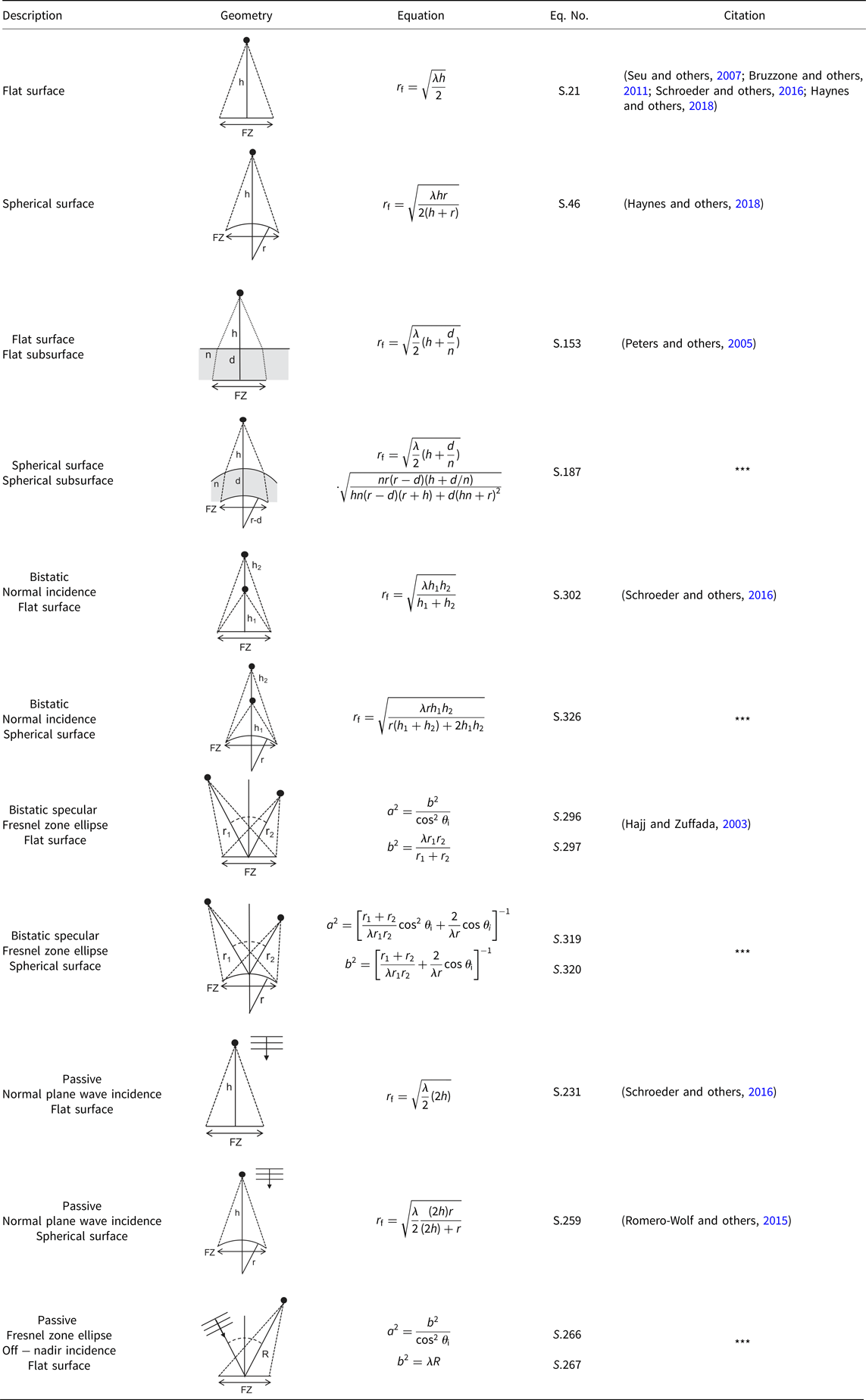
Section 2 contains lookup tables that summarize the results. Each table row includes a short description of the geometry, a graphical representation of the geometry, the equation and citation, as well as the section and equation numbers in the Supplementary Material where derivations can be found. New variants, or those for which citations were not readily found, are noted with ***. Derivations rely largely on image methods, large-argument approximations, small-angle approximations and scalar surface phase integrals under the assumption of Kirchhoff scattering. Observations, recommendations and commentary are included throughout the derivations to help draw attention to notable connections between results.
While the primary application is low-frequency radar sounding, the equations are general enough that the user can augment these for their particular problem and radar system. The list is not exhaustive, and more advanced variants and combinations exist and can be derived, for instance expressions that contain integrals over angle-dependent antenna beam patterns or scattering functions.
The organization of the paper is as follows: Section 1.1 has a list of assumptions and conventions used throughout the work and which help to use the tables. Section 2 contains the lookup tables, including one for Fresnel zone radius. Derivations can be found in the Supplementary Material: Section S1 contains the derivations for surface geometries. Section S2 covers subsurface geometries. Section S3 covers pulse limited surface and subsurface geometries. Section S4 covers passive radar sounding for surface targets. Finally, Section S5 contains derivations for bistatic geometries and bistatic Fresnel zones.
1.1. Using the tables
The following assumptions and conventions apply to the radar equations, geometries and derivations that are summarized in the tables in Section 2:
1. Radar equations give single-pulse raw received power. Processing gains, synthetic aperture radar (SAR) resolution target area and system losses are not included.
2. Distances between sensors and targets are assumed large compared to the wavelength. Most derivations rely on large-argument/small-angle approximations.
3. All expressions for Fresnel zone radius, r f, in the table are approximations.
4. The medium above the surface interface is assumed to be free-space.
5. Angular dependence and polarization of backscatter, antenna gain, reflectivity or transmissivity are suppressed for clarity.
6. Subsurface media are assumed lossless. Propagation losses can be included as needed.
7. Interfaces to which reflectivity, Γ, and transmissivity, T, apply should be understood in context.
8. Surface phase integrals implicitly start from the assumption of Kirchhoff scattering.
9. Any occurrence of reflectivity, Γ, and transmissivity, T, can be augmented with higher-fidelity scattering models that are proportional to reflectivity or transmissivity. For example, the exponential form of coherence loss derived under the Kirchhoff approximation for small-roughness can be included at any interface.
10. Transmitter and receiver gain, G t and G r, are notated separately, rather than G 2, to accommodate bistatic geometries or systems that transmit and receive from different, but possibly co-located, antennas.
2. Tables of radar equations and fresnel zone radius
In all tables, subsurface is indicated with grey shading in the column Geometry, and new variants of equations, or those for which citations were not readily found, are noted with *** in the column Citation.
Table 1. Table of symbols
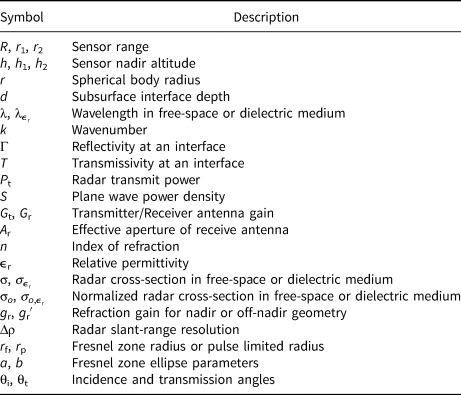
Table 2. Active sounding – surface
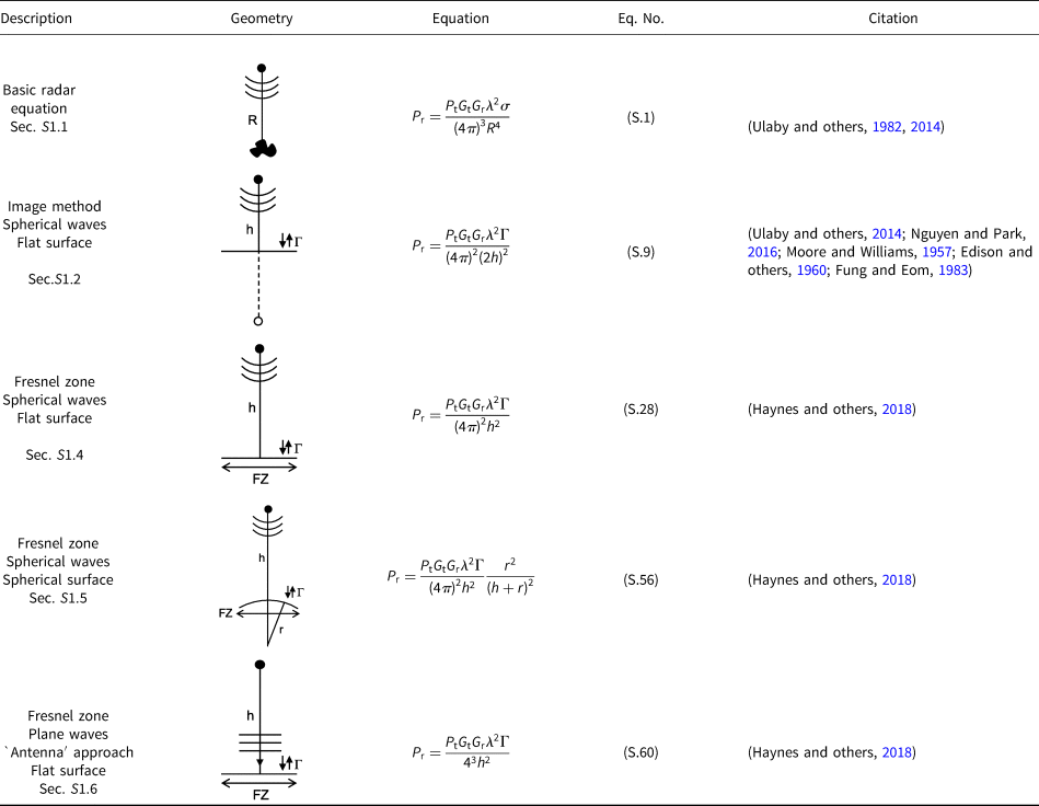
Table 3. Active sounding – subsurface
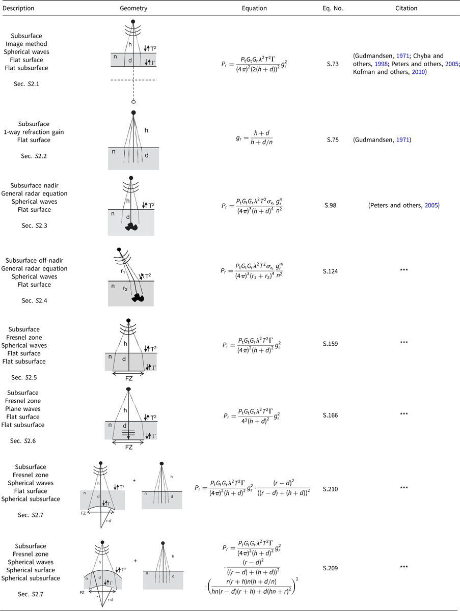
Table 4. Pulse limited

Table 5. Passive sounding

Table 6. Bistatic
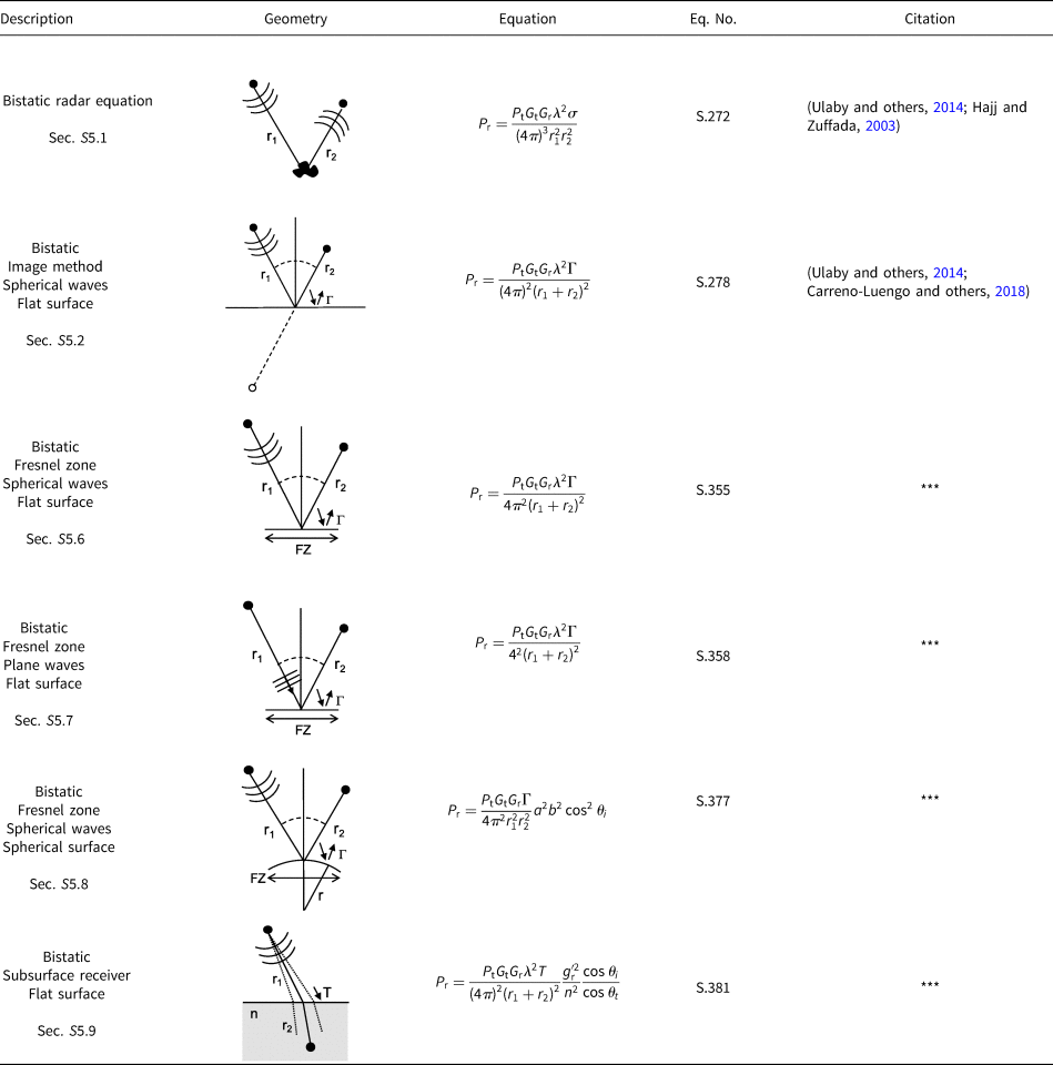
Table 7. Fresnel zone radius
Supplementary material
The supplementary material for this article can be found at https://doi.org/10.1017/aog.2020.16.
Acknowledgments
The author thanks several people who contributed generous time and energy to carefully reading, editing and checking this work, which has greatly improved its substance, presentation and usefulness. Ilgin Seker (JPL) for reading a first draft and providing several insights; Dragana Perkovic-Martin (JPL) for reviewing an early draft; Dustin Schroeder (Stanford) for encouraging its publication as well as participation from his students: Riley Culberg (Stanford), Anna Broome (Stanford), Nicole Bienert (Stanford) and Sean Peters (Stanford), who each contributed numerous valuable suggestions and corrections, both detailed and nuanced, on content, style, references, table entries and figures. The author would also like to thank the two anonymous reviewers for their careful reading of the work and helpful improvements.
The research was carried out at the Jet Propulsion Laboratory, California Institute of Technology, under a contract with the National Aeronautics and Space Administration. This work was supported in part by the Europa Clipper Project. Government sponsorship acknowledged.


