1. Introduction
In recent years, minimally invasive surgery techniques have been considerably preferred in different surgical fields, for example, gynecological, urological, and gastrointestinal. In contrast to conventional open surgeries, small incisions are made to allow the insertion of surgical instruments into the patient’s body, allowing a shorter recovery time [Reference Grau, Lingamfelter, Ponzio, Post, Ong, Le and Orozco1]. Research has therefore focused on the development of robotic systems dedicated to assisting surgeons in this type of intervention, in order to allow them to operate in the best conditions, thus improving the precision and dexterity of their gestures even in complex procedures and reducing surgical time while guaranteeing patient safety [Reference Kuo and Dai2, Reference Laribi, Arsicault, Riviere and Zeghloul3].
One of the most common applications of minimally invasive surgery involves procedures in the abdominal region, commonly known as laparoscopy. In this context, a laparoscope, that is, a thin, lighted tube with a camera at its tip, is inserted into the abdominal region through a small incision. The camera transmits a video stream of the abdominal cavity to a monitor, providing the surgeon with visual feedback on his actions. The surgeon also makes additional small cuts to insert the instruments needed to perform the operation. A medical assistant is typically in charge of moving the laparoscope according to the surgeon’s orders, which can result in a loss of instrument tracking accuracy and longer operating times depending on the assistant’s level of experience, while also increasing the surgeon’s stress level [Reference Abbas, Holder-Haynes, Taylor, Scott, Brandt and Naik-Mathuria4]. To overcome these problems, researchers have been developing innovative robotic solutions since the introduction of the Automatic Endoscopic System for Optimal Positioning in 1993. This breakthrough has paved the way for a range of innovative platforms in the field of laparoscopic surgery. An important development in surgical robotics, for instance, was the ZEUS robotic system, which combined laparoscopic instruments with teleoperated surgery [Reference George, Brand, LaPorta, Marescaux and Satava5]. The da Vinci Surgical System has become the most widely used robotic surgery device in the field, providing surgeons with enhanced capabilities for precise and minimally invasive procedures. Furthermore, a robot-assistant laparoscopic holder platform has recently been proposed by the CoBRA team of Pprime Institute to manipulate the laparoscope and autonomously track the surgeon’s movements [Reference Sandoval, Laribi, Faure, Breque, Richer and Zeghloul6]. This platform uses a serial collaborative robot with 7 degrees of freedom (DoF) as laparoscope-holder, leaving the surgeon’s hands-free to operate, giving him a better vision of the surgical procedure, with a high-definition view of the instrument’s movements inside the patient’s body. Once the laparoscope inserted into the abdominal cavity, through the trocar placed at the small incision made, the robot’s motion is therefore limited to only four DoF. In fact, the kinematic constraint caused by the trocar, known as a remote center of motion (RCM) constraint [Reference Sadeghian, Zokaei and Hadian Jazi7], affects the kinematic and dynamic behavior of the robot [Reference Aghakhani, Geravand, Shahriari, Vendittelli and Oriolo8].
Numerous strategies have been developed to overcome the loss-of-mobility problem caused by the RCM constraint in robots that do not mechanically integrate this constraint. These strategies can be divided into two categories: control-based and design-based techniques. The first approach relies on the proper knowledge of the robot kinematic model and a suitable trajectory generator to correctly place and orient the medical tool [Reference Yang, Wang, Xie, Levine, Davoodi and Li9], while more advanced techniques using compliance laws and robot redundancy can also be cited here [Reference Sandoval, Poisson and Vieyres10, Reference Sadeghian, Villani, Keshmiri and Siciliano11]. However, these techniques do not guarantee the feasibility of every desired pose during the execution of the tracking task, especially when various constraints must be satisfied. On the other hand, the design-based approach provides the most effective solution for improving robot performance and, consequently, tool motion generation [Reference Kuo, Dai and Dasgupta12]. According to previous studies, accessibility and dexterity of the task workspace can be improved by finding the optimal base position. This problem has generated considerable interest, particularly in industry. For example, researchers have analyzed the optimal placement of robots to improve their capabilities, such as the best surface coverage [Reference Kalawoun, Lengagne and Mezouar13], the best reachability of task area [Reference Vahrenkamp, Asfour and Dillmann14], and the shortest cycle time to perform specific tasks [Reference Spensieri, Carlson, Bohlin, Kressin and Shi15]. Furthermore, authors in [Reference Zeghloul and Pamanes-Garcia16] propose a multicriteria technique to automatically identify the best robot base placement in a constrained environment. In the field of surgery, the optimization of robot placement has also been explored to improve both robot performance and surgical quality [Reference Feng, Jin, Tong, Guo, Zhao and Fu17]. In our previous work [Reference Trabelsi, Sandoval, Mlika, Lahouar, Zeghloul, Cau and Laribi18], we have investigated the optimal base placement for a multirobot platform, aiming to enhance the surgical platform’s kinematic capability.
Besides the optimal base placement, the tool mounting (position and orientation) at the end effector plays a critical role in determining the performance of the robot arm. Recent research highlights that the orientation of the tool is a key parameter that significantly impacts task performance [Reference Liang19]. Specifically, the mounting orientation of the tool affects the reachability and the dexterity of surgical tasks, particularly when instruments need to pass through small openings in the patient’s body. The proper mounting orientation of the tool is then essential for ensuring that the robot arm can effectively navigate within constrained spaces during surgical procedures [Reference Pham, Coutinho, Leite, Lizarralde, From and Johansson20], while avoiding robot singularities, steady-state errors, and patient-robot collisions.
In this research work, we aim to present a novel framework to simultaneously identifying the optimal robot base placement and tool mounting configuration of a serial redundant robot, enhancing the robot accuracy and dexterity during laparoscopic surgery. For this purpose, a study of the robot’s capability was performed to effectively address the various restrictions. This information illustrates the relationship between the robot’s end-effector and its base, revealing the areas that can be reached by the tool in a versatile manner during the task. To this end, a capability map, which is a precomputed discretized mapping of the robot workspace that encodes the set of all possible end-effector poses [Reference Zacharias, Borst, Wolf and Hirzinger21], was implemented for the laparoscopic task. An innovative multiobjective algorithm was created to exploit the information provided by this map to identify the optimal configurations for the robotic system. The optimization of the robotic platform design parameters is then performed to improve its kinematic and dynamic performance. The main contribution of this framework is that it allows to simultaneously study the optimal placement of a redundant serial robots’ base and its medical instrument mounting, by proposing a multiobjective optimization algorithm to improve the kinematic and dynamic behavior’s platform. In addition, the robot capability map allows to simplify the optimization problem and reduces the computation time.
This paper is organized as follows. A description of the robot-assistant camera holder platform and an overview of the optimization problem are detailed in Section 2. The generation of the robot capability map is introduced in Section 3. Section 4 carries out the formulation of the optimization problem using genetic algorithm techniques and the selection framework of the optimal solution from the Pareto front. Section 5 presents a discussion and representation of the optimal solution followed by the robotic platform validation. Then, the conclusion and the perspectives of the current study are presented in the last section.
2. Problem statement
Numerous common surgical procedures can now be performed laparoscopically. Some robotic platforms, such as the DaVinci surgical robot from Intuitive Surgical or more recently the Hugo RAS system from Medtronic, are available to operate in medical procedures. In the same way, other assisting platforms are also emerging, as the robotic assistant laparoscopic holder platform proposed in ref. [Reference Sandoval, Laribi, Faure, Breque, Richer and Zeghloul6]. The robotic platform is principally composed of a redundant serial robot with 7-DoF to hold and position the camera according to the surgeon’s hand movements with the surgical instrument. The laparoscope provides real-time visual feedback to the surgeon to help him monitoring the procedure and keep him focused on the task. The proposed platform is shown in Fig. 1. During the surgical procedure, the surgeon manipulates the instruments while the robot autonomously follows the tips of the tools online, using a motion tracking sensors placed on the surgical instruments.

Figure 1. Robot-assisted camera holder platform [Reference Sandoval, Laribi, Faure, Breque, Richer and Zeghloul6].
Laparoscopic surgery is subject to several constraints. One of the most relevant is the tool workspace. As soon as the patient’s abdominal cavity is accessed, the camera must always pass by a fixed point (RCM) that is precisely determined by the specified incision point provided by the surgical staff depend on the type of surgical procedure, the targeted organ or area and the patient anatomy, as shown in Fig. 2a. Only three rotations and one translation can be achieved, as depicted in Fig. 2b. Based on the operation’s type,that is, the organs’ desired access and the body’s anatomy, the surgeon can decide where to place this RCM.

Figure 2. (a) Abdominal cavity insertion region and (b) the laparoscopic workspace.
Therefore, in order to access the task and successfully navigate the whole workspace of the laparoscopic camera defined by a cone with an apex angle α of 52 degrees [Reference Laribi, Riviere, Arsicault and Zeghloul22], represented in Fig. 3a, the robot must be well positioned in the operating room in relation to the patient. Furthermore, an optimization algorithm is employed to improve the robot’s kinematic and dynamic behavior. In addition to the location of the base, the mounting of the tool has a significant impact on the robot’s ability to perform the task, interact with the patient, and avoid collisions during the operation.
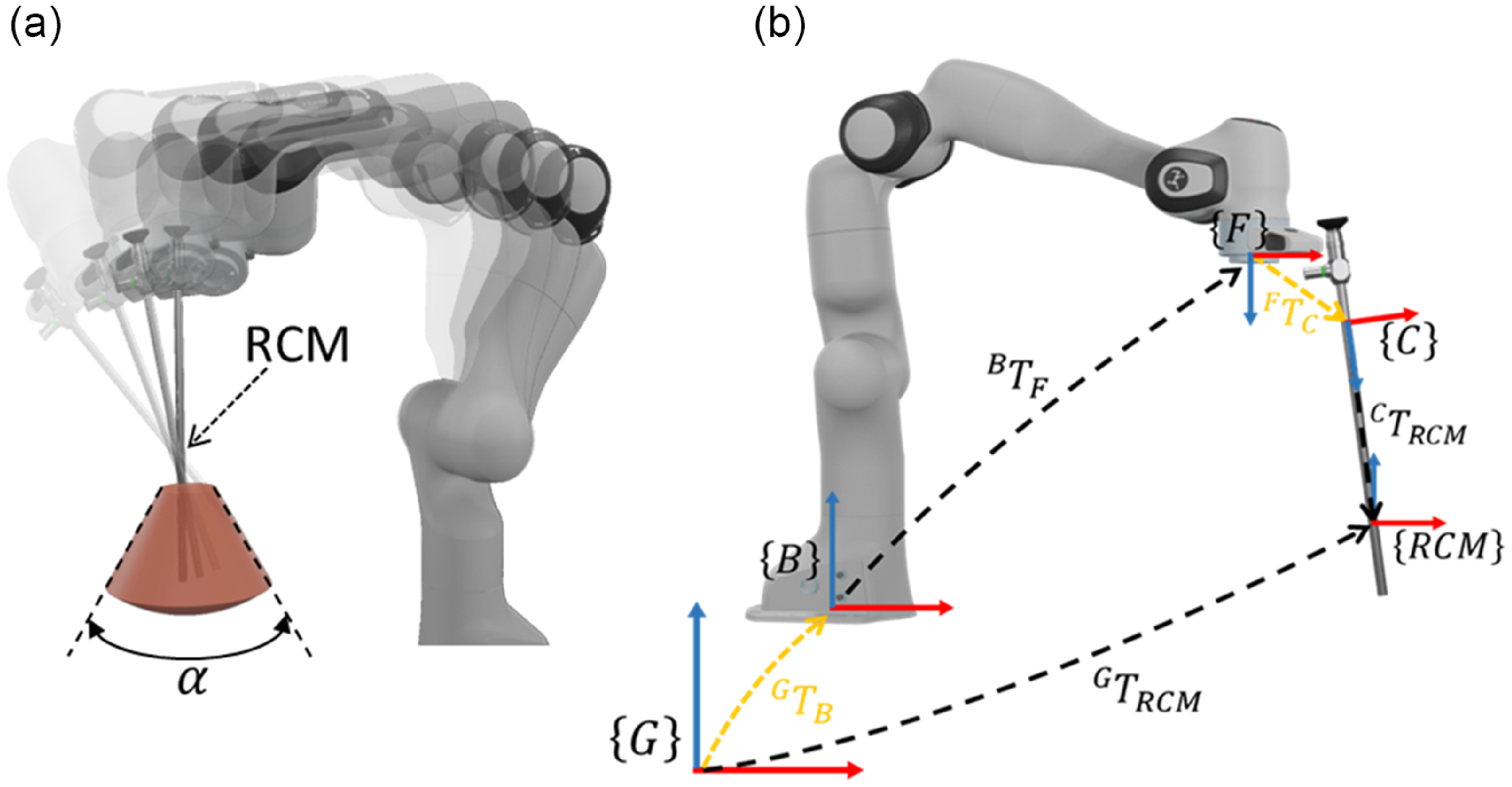
Figure 3. Camera-holder robot: (a) RCM constraint of the surgical task, (b) reference frames for the placement optimization.
An optimization algorithm has to search through all possible base configurations {B} in relation to the global frame {G}, and also the laparoscopic camera mounting in relation to the flange frame {F} in order to identify the optimal one. As illustrated in Fig. 3b, the optimization problem seeks to identify the homogeneous transformation matrix parameters shown in yellow
![]() ${ }^{G}{T_{B}}{}$
and
${ }^{G}{T_{B}}{}$
and
![]() ${ }^{F}{T_{c}}{}$
. The other transformation matrices are defined by the features of the problem, such as the incision points location and the RCM
${ }^{F}{T_{c}}{}$
. The other transformation matrices are defined by the features of the problem, such as the incision points location and the RCM
![]() ${ }^{G}{T_{RCM}}{}$
provided by the surgeon, the geometrical parameters of the camera defined by
${ }^{G}{T_{RCM}}{}$
provided by the surgeon, the geometrical parameters of the camera defined by
![]() ${ }^{c}{T_{RCM}}{}$
, and the position of the flange with respect to the robot base
${ }^{c}{T_{RCM}}{}$
, and the position of the flange with respect to the robot base
![]() ${ }^{B}{T_{F}}{}$
, as determined by the capability map provided in the following section.
${ }^{B}{T_{F}}{}$
, as determined by the capability map provided in the following section.
3. Capability map
A capability map is a powerful tool to represent the workspace of a serial robot encoding the position and orientation reachability of its end-effector with respect to the robot’s base coordinate system {B} [Reference Vahrenkamp, Asfour and Dillmann14]. As not all the orientations are feasible for the same reachable position, the capability map describes the 6 DoF of the robot workspace. Each component of this map is represented as voxel data, including information about the position and all reachable orientations. As presented in ref. [Reference Makhal and Goins23], this information is grouped in structures suitable for visualization and easy access.
A spatial data structure is constructed through an offline process to generate a representation of the robot’s reach capabilities. In accordance with previous works [Reference Trabelsi, Sandoval, Mlika, Lahouar, Zeghloul, Cau and Laribi18], we outline a three-stage process for developing a capability map for a serial redundant robot. In this section, we briefly summarize its key points.
The continuous robot arm workspace
![]() $(V_{ws})$
has a bounding box with a lateral length corresponding to the maximum reach of the manipulator centered on the base of the robot. We discretize
$(V_{ws})$
has a bounding box with a lateral length corresponding to the maximum reach of the manipulator centered on the base of the robot. We discretize
![]() $V_{ws}$
into n voxels as
$V_{ws}$
into n voxels as
![]() $\bigcup _{i=1}^{n}v_{e}$
where
$\bigcup _{i=1}^{n}v_{e}$
where
![]() $v_{e}$
denotes the discrete elements cube volume and i the voxel index, as depicted in Fig. 4a. Information about the possible tool center point (TCP) orientations in relation to the occupied volume is stored in each voxel. In this work, the robot camera-holder platform is composed of a 7-Dof Franka robot. In the laparoscope guiding application, the robot’s usable workspace is limited to the front site; therefore, we simply mapped the front volume to reduce the map size and computation time and define the elementary voxel volume
$v_{e}$
denotes the discrete elements cube volume and i the voxel index, as depicted in Fig. 4a. Information about the possible tool center point (TCP) orientations in relation to the occupied volume is stored in each voxel. In this work, the robot camera-holder platform is composed of a 7-Dof Franka robot. In the laparoscope guiding application, the robot’s usable workspace is limited to the front site; therefore, we simply mapped the front volume to reduce the map size and computation time and define the elementary voxel volume
![]() $v_{e}$
as a cube of edge length
$v_{e}$
as a cube of edge length
![]() $l_{c}$
=0.05m.
$l_{c}$
=0.05m.
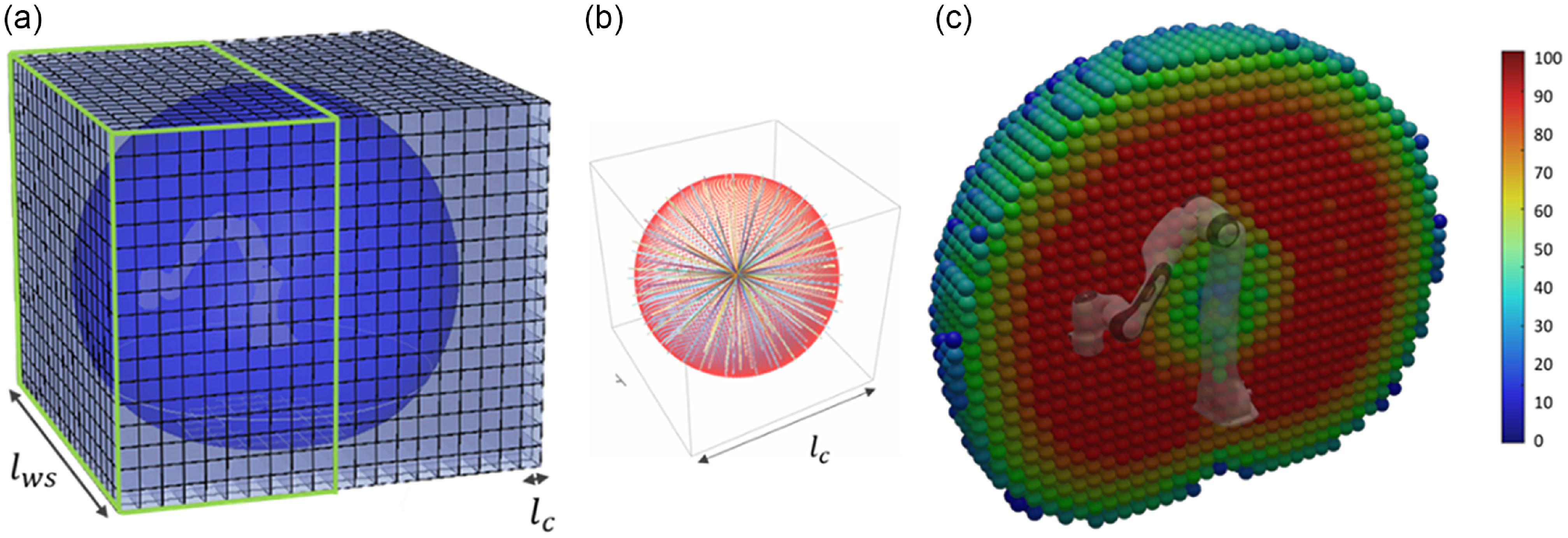
Figure 4. Capability map generation: (a) R3 workspace discretization, (b) Discretization of so(3), (c) IKM validation and 3D HSV color representation of the reachability index.
Once we have obtained a valid workspace discretization, we can proceed with the mapping of the three remaining components representing the orientation of TCP. The voxels serve as containers for the data represented in the capability map. This information is represented by discretizing the orientation space in the Special Orthogonal group SO(3). This step is divided into two parts. The first part consists of inserting a sphere with a diameter equal to the voxel’s edge length
![]() $l_{c}$
into each voxel to produce uniformly distributed orientations in the SO(2) space. The sphere’s center and the voxel’s center are the same. Using the spiral point algorithm proposed by [Reference Saff and Kuijlaars24] on the sphere, a set of S uniformly distributed points is generated, and for each point Si an orientation is performed, as shown in Fig. 4b. The last missing coordinate is the roll angle of the tool. The second part involves a self-rotation about the z-axis of the TCP [Reference Zacharias, Borst, Wolf and Hirzinger21]. We rotated by a constant stepsize of
$l_{c}$
into each voxel to produce uniformly distributed orientations in the SO(2) space. The sphere’s center and the voxel’s center are the same. Using the spiral point algorithm proposed by [Reference Saff and Kuijlaars24] on the sphere, a set of S uniformly distributed points is generated, and for each point Si an orientation is performed, as shown in Fig. 4b. The last missing coordinate is the roll angle of the tool. The second part involves a self-rotation about the z-axis of the TCP [Reference Zacharias, Borst, Wolf and Hirzinger21]. We rotated by a constant stepsize of
![]() $\frac{2\pi }{r}$
for all the possible orientations in S.
$\frac{2\pi }{r}$
for all the possible orientations in S.
Thus, each voxel contains
![]() $s*r$
frames. In this study, we used a uniform distribution of s = 200 points across the spherical surface and a
$s*r$
frames. In this study, we used a uniform distribution of s = 200 points across the spherical surface and a
![]() $\frac{2\pi }{4}$
constant rotation about the TCP z-axes. These 800 frames represent the SO(3) discretization given in a coordinate system placed at the voxel center. To create a Franka robot’s capability map, the TCP’s reachable orientations for each voxel must be determined. An inverse kinematics model (IKM) validation procedure is used to examine all the frames and, if a valid solution is found by the IKM [Reference He and Liu25], which means that the pose is reachable, it is assigned a value of 1 in the capacity map, otherwise, a value of 0 is assigned.
$\frac{2\pi }{4}$
constant rotation about the TCP z-axes. These 800 frames represent the SO(3) discretization given in a coordinate system placed at the voxel center. To create a Franka robot’s capability map, the TCP’s reachable orientations for each voxel must be determined. An inverse kinematics model (IKM) validation procedure is used to examine all the frames and, if a valid solution is found by the IKM [Reference He and Liu25], which means that the pose is reachable, it is assigned a value of 1 in the capacity map, otherwise, a value of 0 is assigned.
A simple algorithm for resuming the generation of capability maps is presented below.
Algorithm 1. Generate Capability Map

The capability map represents the grouping of all voxel data. We used to present the kinematic capabilities of the robot and visualize the accessibility of the workspace. All these data are stored within a database and will subsequently be utilized within the context of this project to ascertain the most advantageous construction parameters for the robot camera-holder platform. This tool is designed to improve the performance of optimization algorithms and decrease the amount of time required for computations. A simple graphical representation of the capability map data of the robotic platform is presented in Fig. 4c. The colors of the spheres are determined by the reachability index, which is determined by the percentage of directions in the voxel (v) with an inverse kinematic solution relative to the total number of discretized orientations.
4. Optimization problem formulation
The robotic platform presented in this paper to assist laparoscopy consists mainly of a serial redundant robot. The purpose of this research is to enhance the dynamic behavior of the laparoscope robotic assistant in order to take advantage of the torque and the active compliance control laws to meet a collaborative system in a complex indoor environment such as an operating room. Moreover, the various restrictions of the tool’s workspace as well as accessibility limitations need to be addressed. In order to achieve this goal, it is crucial to identify the optimal positioning of the robot base as well as the most effective configuration for mounting the tools. This will serve to improve the overall dynamic performance. The problem of identifying the two transformation matrices allows for multiple potential solutions. For this reason, an optimization problem will be formulated to identify the optimal solutions leading to the optimal configuration of the robotic platform.
The proposed optimization algorithm strategy guarantees task accessibility and efficient robot behavior in the optimal configuration found between all possible robot placement and surgical camera mounting designs. In other words, a nine variables design vector is provided for the optimal robot placement and tool mounting homogeneous transformation matrices
![]() ${ }^{G}{T_{B}}{}$
and
${ }^{G}{T_{B}}{}$
and
![]() ${ }^{F}{T_{c}}{},$
as shown in fig. 5. According to the manufacturer’s instructions [26], the Franka robot must always be placed on a horizontal plane. As result, the transformation matrix
${ }^{F}{T_{c}}{},$
as shown in fig. 5. According to the manufacturer’s instructions [26], the Franka robot must always be placed on a horizontal plane. As result, the transformation matrix
![]() ${ }^{G}{T_{B}}{}$
of the robot base frame regards to the global frame is given by Eq. (1), only the translation parameters
${ }^{G}{T_{B}}{}$
of the robot base frame regards to the global frame is given by Eq. (1), only the translation parameters
![]() $x$
,
$x$
,
![]() $y$
, and
$y$
, and
![]() $z$
are needed to identify.
$z$
are needed to identify.
 \begin{equation} { }^{G}{T_{B}}{}=\left[\begin{array}{c@{\quad}c} \mathbf{I}_{3\times 3} & \begin{array}{c} x\\ y\\ z \end{array}\\ 000 & 1 \end{array}\right] \end{equation}
The parameters of the homogeneous transformation matrix
![]() ${ }^{F}{T_{c}}{}$
describing the camera mounting with respect to the robot flange are then given by Eq. (2). The 6-DoF are defined by the
${ }^{F}{T_{c}}{}$
describing the camera mounting with respect to the robot flange are then given by Eq. (2). The 6-DoF are defined by the
![]() $(x_{c},y_{c}, z_{c})$
translation vector of the camera frame to the robot flange frame and by the matrix
$(x_{c},y_{c}, z_{c})$
translation vector of the camera frame to the robot flange frame and by the matrix
![]() $R(\alpha _{c},\beta _{c},\sigma _{c})$
representing the tool’s orientation. The last consists of 3 rotations: roll angle
$R(\alpha _{c},\beta _{c},\sigma _{c})$
representing the tool’s orientation. The last consists of 3 rotations: roll angle
![]() $\alpha _{c}$
around x-axis, pitch angle
$\alpha _{c}$
around x-axis, pitch angle
![]() $\beta _{c}$
around y-axis, and yaw angle
$\beta _{c}$
around y-axis, and yaw angle
![]() $\sigma _{c}$
around z-axis.
$\sigma _{c}$
around z-axis.
 \begin{equation} { }^{F}{T_{c}}{}=\left[\begin{array}{c@{\quad}c@{\quad}c@{\quad}c} & & x_{c}\\& R\left(\alpha _{c},\beta _{c},\sigma _{c}\right) & x_{c}\\& & y_{c}\\0 & 0 & 0 & 1\end{array}\right] = \left[\begin{array}{c@{\quad}c@{\quad}c@{\quad}c} r_{11} &r_{21} & r_{31} & x_{c}\\ r_{12} &r_{22} & r_{32} & y_{c}\\ r_{13} &r_{23} & r_{33} & z_{c}\\ 0 & 0 & 0 & 1 \end{array}\right] \end{equation}
The platform configuration can be formulated as an optimization problem with a design vector
![]() $\mathbf{X}$
, which includes all the parameters of the transformation matrices presented in Eq. (3). The optimal solution takes into account the tool workspace limits, mounting constraints, and objective functions that ensure task accessibility and enhanced robot behavior.
$\mathbf{X}$
, which includes all the parameters of the transformation matrices presented in Eq. (3). The optimal solution takes into account the tool workspace limits, mounting constraints, and objective functions that ensure task accessibility and enhanced robot behavior.
4.1. Formulation problem
In order to improve the kinematic behavior of the camera holder robot and identify the optimal design vectors, a multicriteria optimization algorithm is defined as follows:
 \begin{align} \left\{\begin{array}{c} \text{minimize}\, \left(-W\left(\mathbf{X}\right),-A\left(\mathbf{X}\right), D\left(\mathbf{X}\right)\right)\\[5pt] \text{subject to}\\[4pt] \boldsymbol{{LB}}\lt \mathbf{X}\lt \boldsymbol{{UB}}\\[4pt] w_{t}\subset W_{ws}\\[4pt] d\geq d_{min}\\[4pt] \text{with}, \mathbf{X}=\left[x,y,z,\alpha _{c},\beta _{c},\sigma _{c},x_{c},y_{c}, z_{c}\right] \end{array}\right. \end{align}
The optimal solution can be formulated using several criteria. According to the medical field, several standards are imposed. In this paper, we focus on the two most appropriate criteria for our medical task, namely the system’s accessibility and the RCM poses’ manipulability measure.
The manipulability stands as a crucial benefit in integrating robotics into laparoscopic surgery, as it greatly enhances the dexterity of conventional surgical procedures. The robotic platform should have no singularity or degeneracy to achieve full mobility throughout the task workspace [Reference Togai27]. Yoshikawa [Reference Yoshikawa28] introduced the manipulability index, a measure for redundant manipulator quality to describe the distance to singular configurations. The index represents the robot’s TCP ability to change its position and orientation arbitrarily and can be used to promote positions with better dexterity leading to more efficient adaptation during task execution. The manipulability index
![]() $W(\boldsymbol{{q}}_{\boldsymbol{{X}}})$
is computed as a function of the robot Jacobian matrix
$W(\boldsymbol{{q}}_{\boldsymbol{{X}}})$
is computed as a function of the robot Jacobian matrix
![]() $\mathbf{J}(\boldsymbol{{q}}_{\boldsymbol{{X}}})$
, where
$\mathbf{J}(\boldsymbol{{q}}_{\boldsymbol{{X}}})$
, where
![]() $\boldsymbol{{q}}_{\boldsymbol{{X}}}$
is the instantaneous joint configuration of the robot manipulator.
$\boldsymbol{{q}}_{\boldsymbol{{X}}}$
is the instantaneous joint configuration of the robot manipulator.
The workspace of a serial robot is defined by the mechanical design of the robot. Knowing where to perform tasks allows us to identify the best layout of the robotic platform. In order to optimize the kinematic and dynamic behavior of our platform, information about the accessibility of the task workspace is crucial. Using the capability map, an accessibility representation of the robot workspace is expressed as a reachability index given in Eq. 6. This index is defined by the percentage of directions in the voxel
![]() $(v_{X})$
with an inverse kinematic solution to the total number of discretized directions.
$(v_{X})$
with an inverse kinematic solution to the total number of discretized directions.
 \begin{align} A\left(v_{\boldsymbol{{X}}}\right)=100\frac{\sum _{i=1}^{m}R\left(v_{X},i\right)}{m}\qquad\qquad\qquad\qquad\qquad\nonumber\\\!\!\!\!\!\!\!\!\textrm{where:}\quad\qquad\qquad\qquad\qquad\qquad R(v_{\boldsymbol{{X}}},i)=\begin{cases} 1 & \text{Accessible direction}\\0 & \textit{otherwise} \end{cases}\qquad\qquad\qquad\qquad\qquad\end{align}
The distance between the robot end effector and the tool has an impact on the robot’s behavior. As the distance increases, the robot manipulability and task accessibility decreases. The distance D between the origins of the camera mounting frame and the robot flange frame, as depicted in Equation 2 and illustrated in Fig 5, is computed as follows:

Figure 5. Overview of the coordinate system.
A constraint validation is required to meet the tree criteria, manipulability
![]() $W(\mathbf{X})$
, accessibility
$W(\mathbf{X})$
, accessibility
![]() $A(\mathbf{X})$
and camera mounting
$A(\mathbf{X})$
and camera mounting
![]() $D(\mathbf{X})$
. To ensure the proper operation of the robotic assistant camera holder platform, a set of constraints was chosen. An optimization problem is solved by exploring a search space in order to minimize a given function. The optimal solutions are selected within this boundary space. The selection of these limits depends on the problem and the initial conditions. For our optimization problem, the search space represents the space dedicated to the robotic platform placement. The robot is integrated into an operating room where several instruments and equipment are placed. The surgeon determines the possible positioning range of the base of the robotic platform over the operating table. As shown in Fig. 6, the free area for the base is represented by a green cube with the x, y, and z dimensions boundary provided in Table I.
$D(\mathbf{X})$
. To ensure the proper operation of the robotic assistant camera holder platform, a set of constraints was chosen. An optimization problem is solved by exploring a search space in order to minimize a given function. The optimal solutions are selected within this boundary space. The selection of these limits depends on the problem and the initial conditions. For our optimization problem, the search space represents the space dedicated to the robotic platform placement. The robot is integrated into an operating room where several instruments and equipment are placed. The surgeon determines the possible positioning range of the base of the robotic platform over the operating table. As shown in Fig. 6, the free area for the base is represented by a green cube with the x, y, and z dimensions boundary provided in Table I.
Table I. The upper (UB) and lower (LB) boundaries of the design vector variables.

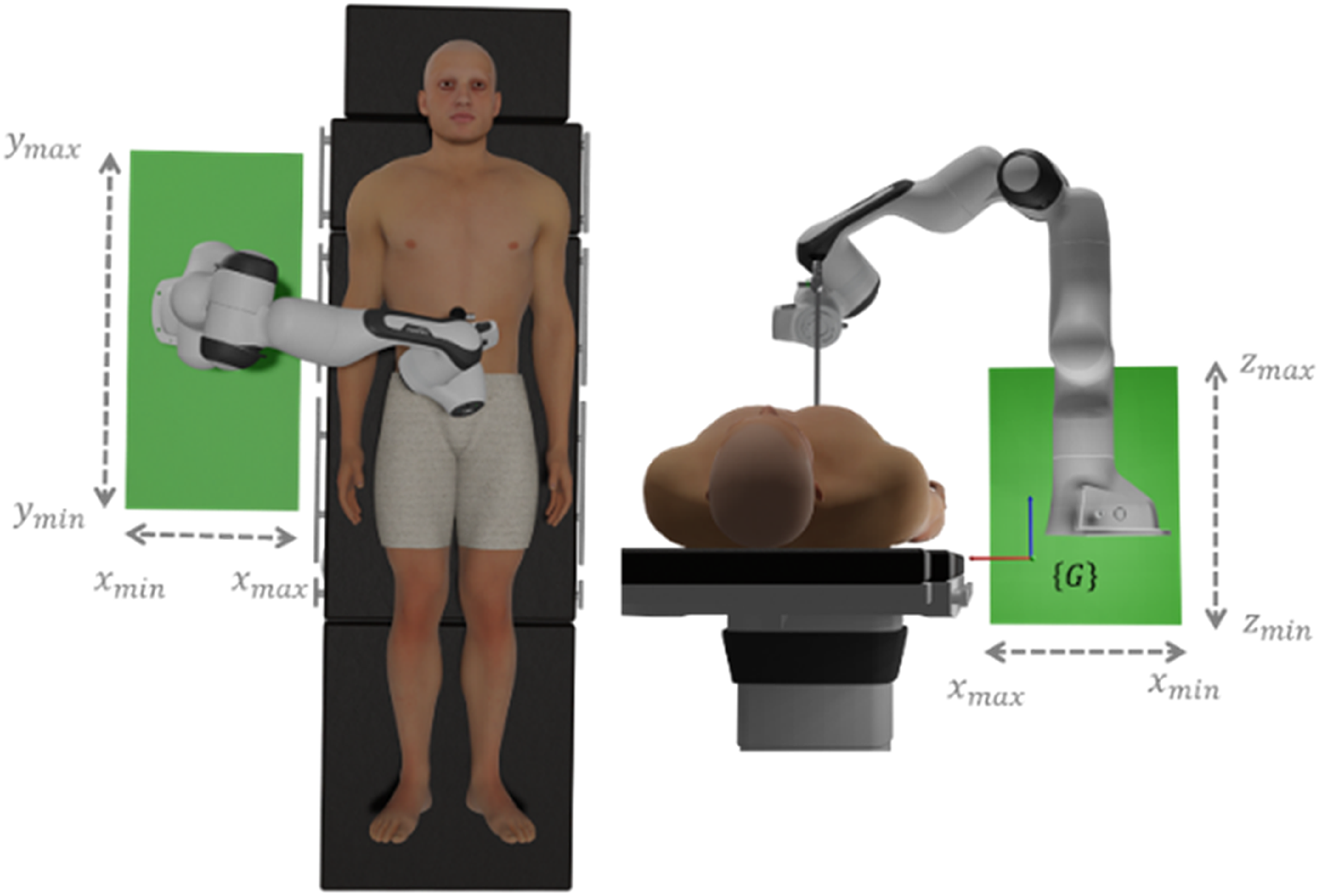
Figure 6. Robot base placement.
The base location determines the first three variables of the design vector, and the remaining variables represent the homogeneous matrix for mounting the camera on the robot. The tool mounting can be located in a sphere with its center at the robot’s flange. To prevent any collision with the surgeon and the patient, the front and the lower part of potential camera mounting sphere are illuminated. As a result, the search space for camera mounting is defined by a quarter sphere, as shown in fig. 7.

Figure 7. Camera mounting boundary representation.
The resolution of the optimization problem depends on the search space to identify the optimal solutions of the design vector defined by Eq. 3. For each variable, we define upper (UB), and lower (LB) boundaries as summarized in Table I.
The workspace of the laparoscopic camera has several constraints and represented by a cone where it allows the 4 DoF. To ensure the validity of the solution of the design vector defined by Eq. 3, it is necessary to guarantee that the entire workspace of the tool (
![]() $w_{t}$
) is accessible.
$w_{t}$
) is accessible.
A discretization of the tool workspace is presented in Fig. 8. Thus, each pose Pi is a tool configuration that allows it to reach a specific position in the task workspace while passing through the RCM. The set of Pi configurations constitutes the surgical camera’s workspace.
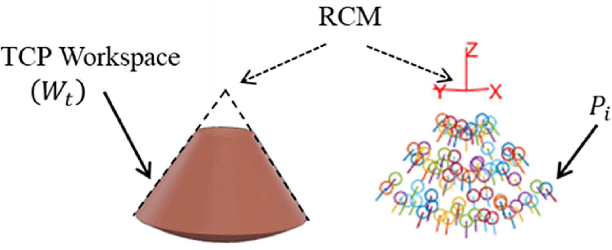
Figure 8. Tool workspace discretization.
The accessibility validation requires that all discrete poses of the task space are accessible; in other words, the platform workspace contains the laparoscopic workspace. As shown in Eq. 9, an inverse kinematic model is used to validate the space
![]() $W_{t}$
, and this latter is considered accessible if and only if all of the poses are reachable.
$W_{t}$
, and this latter is considered accessible if and only if all of the poses are reachable.
 \begin{align} \begin{cases} f\left(P_{i}\right)=1 & \text{Valid IKM solution}\\[5pt] \sum _{i=1}^{n}f\left(P_{i}\right)=n & w_{t}\subset W_{ws} \end{cases} \end{align}
The objective of the optimization algorithm is to identify the parameters of the homogeneous transformation matrix between the camera and the robot flange. These parameters ensure the mounting of the laparoscope by defining the most optimal location and orientation to enhance the kinematic and dynamic behavior of the robotic platform. A mounting feasibility test is presented in this section to identify optimal solutions that are mechanically possible and feasible. A collision detection test is performed among the medical instrument and the robot flange to eliminate the unfeasible solutions along the optimization procedure.
The collision avoidance constraint is defined by the distance between the vortices that envelop the tool and the robot’s end effector, as shown in Fig. 9a. We propose a cylinder of radius 0.02 m and depth 0.35 m for the collision zone of the laparoscope, and two vortexes for the flange: a cylinder of diameter 0.12 m and depth 0.15 m for the link and a cube of size 0.11*0.08*0.04 m for the buttons. In order to detect possible collisions and reject unfeasible solutions, the distances between the two convex geometries are calculated during the optimization algorithm.

Figure 9. Tool and flange collision detection: (a) Envelop definition (b) Minimal distance identification.
The authors of [Reference Gilbert, Johnson and Keerthi29] propose a quick method for calculating the shortest distance between two different convex geometries in 3d space. The points set KA and KB describe the space occupied by objects A in our case the flange of the Franka robot and B the vortex englobing the tool collision volume, as shown in Fig. 9b. The distance d between A and B is indicated by the Eq. 10, where the closest set of points in A and B define the minimal distance.
where “
![]() $dis$
” denotes the Euclidean distance between two 3D points.
$dis$
” denotes the Euclidean distance between two 3D points.
Based on the measured distance between these two vortices, collision identification is established. The sign of the vector (
![]() $K_{Ai},K_{Bj})$
between the two points provides information about whether the two solids overlap. If the norm is positive, it indicates that the two solids do not overlap, and the minimum distance between them is equal to
$K_{Ai},K_{Bj})$
between the two points provides information about whether the two solids overlap. If the norm is positive, it indicates that the two solids do not overlap, and the minimum distance between them is equal to
![]() $d(K_{A},K_{B})$
. Otherwise, the solids collide. Based on the process above, a check collision function developed in Matlab to identifies overlap objects and returns collision information.
$d(K_{A},K_{B})$
. Otherwise, the solids collide. Based on the process above, a check collision function developed in Matlab to identifies overlap objects and returns collision information.
The proposed optimization problem in Eq. 4 is subject to two constraints: the accessibility of the task workspace and the mounting possibility of the camera. In order to make the problem easier to solve, we propose a simplified formulation of the optimization problem by using the penalties function formulation.
The new formalization of the optimization problem is defined as follows:
 \begin{align} \begin{cases} \text{minimize}\, \left(F_{1},F_{2}, F_{3}\right)\left(\mathbf{X}\right)\\[5pt] \mathbf{X}=\left[x,y,z,\alpha _{c},\beta _{c},\sigma _{c},x_{c},y_{c}, z_{c}\right]\\[5pt] \boldsymbol{{LB}}\lt \mathbf{X}\lt \boldsymbol{{UB}} \end{cases} \end{align}
Where:
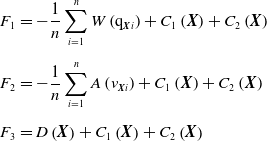 \begin{align} F_{1} & =-\frac{1}{n}\sum _{i=1}^{n}W\left(\mathrm{q}_{\boldsymbol{{X}}i}\right)+C_{1}\left(\boldsymbol{{X}}\right)+C_{2}\left(\boldsymbol{{X}}\right) \nonumber\\[5pt] F_{2} & =-\frac{1}{n}\sum _{i=1}^{n}A\left(v_{\boldsymbol{{X}}i}\right)+C_{1}\left(\boldsymbol{{X}}\right)+C_{2}\left(\boldsymbol{{X}}\right) \\[5pt] F_{3} & =D\left(\boldsymbol{{X}}\right)+C_{1}\left(\boldsymbol{{X}}\right)+C_{2}\left(\boldsymbol{{X}}\right) \nonumber\end{align}
These objective functions are used to represent the different criteria. Function F1 presents the average manipulability of the robot to perform the tool workspace. In order to calculate the average manipulability
![]() $W(\mathrm{q}_{X})$
of the task, a discretization of the tool workspace (
$W(\mathrm{q}_{X})$
of the task, a discretization of the tool workspace (
![]() $W_{t}$
) is presented in Eq. 8. This representation aims to increasing the dexterity of the platform by minimizing the minus value of the task’s average manipulability.
$W_{t}$
) is presented in Eq. 8. This representation aims to increasing the dexterity of the platform by minimizing the minus value of the task’s average manipulability.
Likewise, Function F2 represents the average accessibility index of the robot TCP in order to locate the tool’s workspace in a region where the robot has the best accessibility.
Function F3 represents the capacity of the system to reduce the distance D between the flange and the camera. The constraints turned into penalties are included in the different objective functions, where the reachability of the tool’s workspace is defined by the constraint
![]() $w_{t}\subset W_{ws}$
is transformed as penalty function C1:
$w_{t}\subset W_{ws}$
is transformed as penalty function C1:
 \begin{align} C_{1}\left(\mathbf{X},Wt\right)=\begin{cases} 0 & w_{t}\subset W_{ws}\\[4pt] T_{1} & \text{otherwise} \end{cases} \end{align}
To avoid robot-tool collusion and ensure the assembly feasibility,
![]() $C_{2}$
is used to penalize impossible solutions as follows:
$C_{2}$
is used to penalize impossible solutions as follows:
 \begin{align} C_{2}\left(\mathbf{X}\right)=\begin{cases} T_{2} & Tool/\textit{flange} is \textit{colliding}\left(d\lt d_{min}\right)\\[4pt] 0 & \text{otherwise} \end{cases} \end{align}
where
![]() $T_{1}$
and
$T_{1}$
and
![]() $T_{2}$
are penalty factor constants equal to
$T_{2}$
are penalty factor constants equal to
![]() $1e^{5}$
and
$1e^{5}$
and
![]() $1e^{3}$
, respectively.
$1e^{3}$
, respectively.
4.2. Optimization results
The optimization algorithm searches through all feasible robot placement and surgical camera mounting designs to find the optimal configuration, whereas the optimization algorithm strategy is used to guarantee successful task accessibility and effective robot behavior. Several methods and algorithms are proposed in the literature to solve the optimization problem and identify the optimal configuration. Genetic algorithm method (GA) is an evolutionary optimization method that attempts to find optimal solutions to a cost function by mimicking natural selection and genetic evolution mechanisms [Reference Pitchay and Shorman30]. The GA was chosen for this work due to its ability to explore large search spaces, find global minima more easily, and better deal with problems involving multiple variables.
In this work, the solution of the optimization problem is implemented under Matlab. The GA results aim at identifying the design vector provided by Eq. 3. The domain of research is defined by the upper and lower boundaries given in Table I, and the different objective functions used to maximize the dexterity of the platform and improve the accessibility of the system while keeping the system compact. Multiple solutions coexist forming the Preto Front displayed in Fig. 13. The result is a set of optimal nondominated solutions that present the best compromise between the different objectives, and the set of outcomes is displayed as a convex surface.
Two-dimensional representations of the Pareto front have been provided here in order to make the interpretation of the results obtained slightly easier. Figure 11 depicts the criteria performance of the platform’s manipulability versus reachability versus flange tool distance.
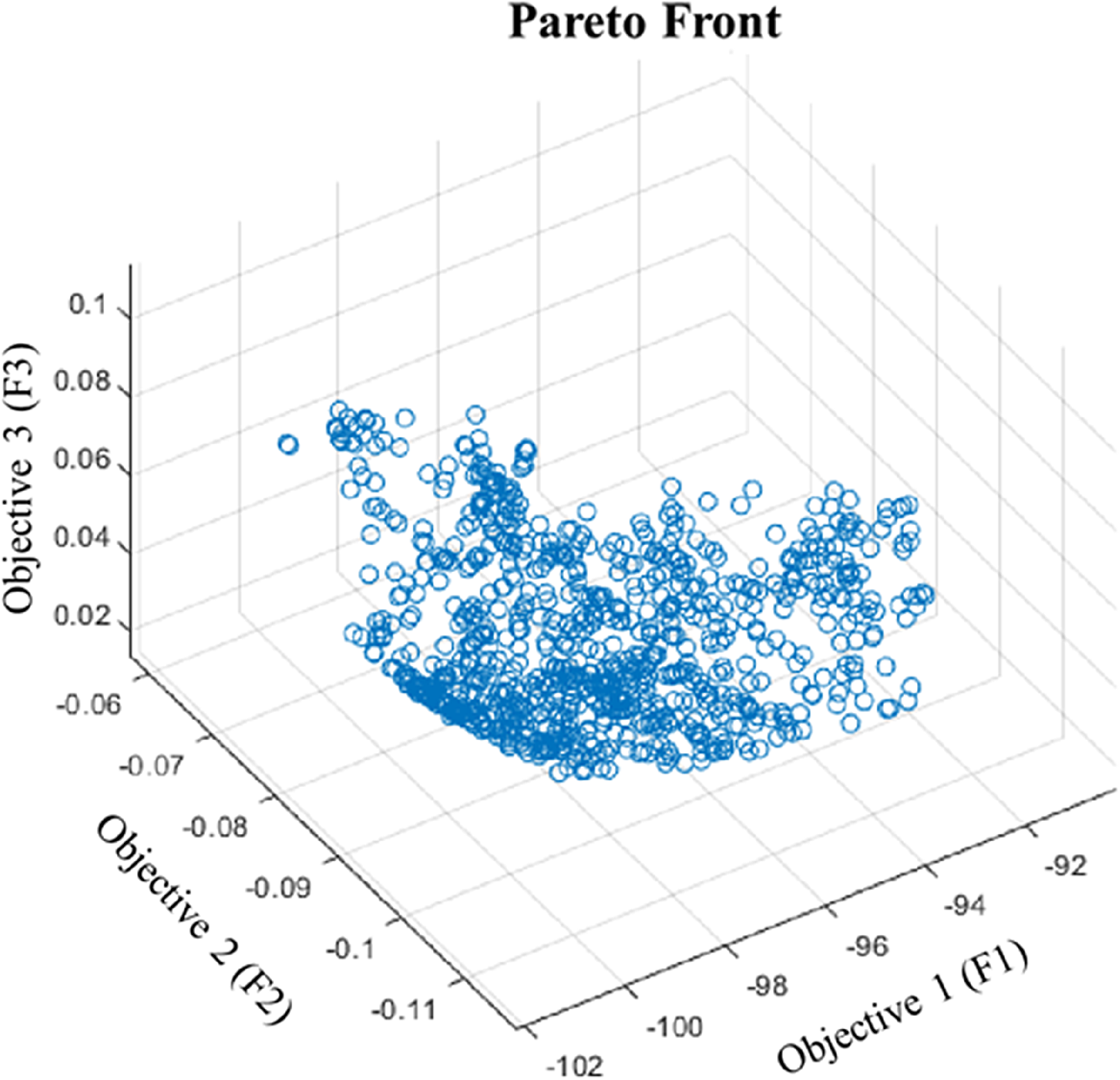
Figure 10. The multi-objective optimization pareto front results.

Figure 11. Bi-objective visualization of the pareto front.
4.2.1. Solution selection protocol
The optimization algorithm’s results show a collection of nondominated optimal solutions. Each of these different solutions can be the optimal configuration because it guarantees the optimal kinetostatic behavior of the robot respecting the different criteria. The choice among these solutions presents a challenge for researchers and manufacturers. This decision is based on a simple selection of a solution from the Pareto front or a choice of one configuration by preferring one criterion over the others.
In this paper, we propose a strategy to select the optimal configuration from the nondominated solutions. This strategy considers the outcomes of the genetic algorithm method and makes use of the Pareto front solutions to identify the most optimal solution for laparoscopic surgical tasks.
The proposed framework to choose the best robotic platform configuration to fulfill a specific task based on optimization results using a genetic algorithm method. This approach employs a new criterion that is applied to the different Pareto front results and allows to select the most suitable platform configuration for the task. Researchers can select multiple criteria for evaluating and scoring the optimal nondominant solutions presented in the Pareto front, such as velocity magnitude, force accuracy, and joint limit avoidance as presented by Pamanes et al. [Reference Pamanes and Zeghloul31]. Active compliance control, that is, in torque control level is commonly applied to the Franka robot in order to control the task with a compliant behavior. The selected evaluation criterion in this study is reducing the power consumption. On one hand, it aims to improve the robot’s dynamic behavior by reducing the joint torques thus avoiding its torque’s limits. On the other hand, it allows to reduce the energy consumed by the actuators of the robotic arm while maintaining the genetic algorithm’s optimal kinetostatic behavior. This criterion is well-suited for evaluating robotic platform designs in the context of precision surgical tasks.
The power applied by a mechanical actuator can be expressed as a function of motor torque
![]() $(\sigma )$
and joint speed
$(\sigma )$
and joint speed
![]() $(\dot{q})$
, as shown in Eq. 15. The goal of this method is to find the platform configuration with the lowest energy consumption among the non-dominant results of the Pareto front.
$(\dot{q})$
, as shown in Eq. 15. The goal of this method is to find the platform configuration with the lowest energy consumption among the non-dominant results of the Pareto front.
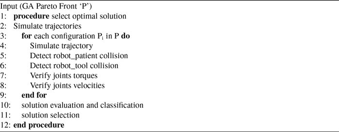
Some Pareto front solutions are invalid when testing surgery-specific trajectories, such as the robot-patient collision and the robot-tool collision as shown in Fig. 12. All these solutions are eliminated by applying collision detection constraints during the simulation validation phase. There are also trajectory validity constraints to consider, such as maximum joint torque and velocity.

Figure 12. Simulation of collision detection: (a) Robot-patient collision, (b) Robot-tool collision.
A robotic platform simulation process is used to develop the selection phase of the ideal configuration. The goal of this procedure is to evaluate the performance of the robotic platform by applying the genetic algorithm’s solutions and simulating them in the context of a medical application. For each solution of the design vector, we test various potential trajectories in the simulation environment built using the Gazebo engine. Then we classify them based on their energy consumption.
The selection stage can be summarized using the following algorithm:
Algorithm 2. Optimal solution selection
The validation trajectories, which simulate feasible trajectories executed by the TCP (laparoscope tip) during a laparoscopy, serve to evaluate the kinematic and dynamic performance of the solutions given by the optimization algorithm. Figure 13a involves a simple trajectory linking two points by activating only 1-DoF, that is, a rotation around the RCM, resulting in the generation of a curve at the laparoscope tip. A second trajectory, shown in Fig. 13b, consists of a complex path that uses the 4-DoF allowed and covers the entire task workspace. In this way, linear trajectories between waypoints are generated. This trajectory verifies that the whole cone is accessible as well as the task space’s boundaries.

Figure 13. Predefined trajectories of the laparoscope tip with different levels of complexity: (a) A simple trajectory connecting two points, (b) a complex path covering the whole task workspace.
In order to speed up the selection process and make the computations simpler, we have narrowed the field down to the 30 solutions distributed on the Pareto front, as shown in Fig. 14. The different solutions are implemented through the selection phase defined by algorithm 2 and validated by the two trajectories shown in Fig. 13. Subsequently, the results are classified based on their energy consumption following simulation analysis under laparoscopic surgery conditions.

Figure 14. Illustration of the chosen solution on the pareto front.
4.2.2. Selection results
The method described above has been applied to the 30 solutions presented in the Pareto front. We simulate the various trajectories for each solution, and this simulation validation enables us to identify the ones that violate dynamic limits like the velocity and torque limits of the joints, as well as those that result in collisions between the robot and other objects in the external environment such as patients, operating tables, and other surgical instruments, as well as self-collision with the tool. Next, we evaluate each solution’s power consumption and present them as shown in Fig. 15.
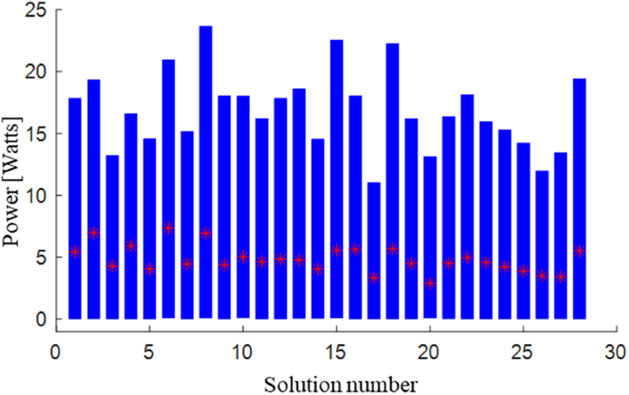
Figure 15. Power consumption of each solution.
Figure 15 shows the variation of the mechanical power consumed by the different actuators of the robotic platform. For each Pareto front solution, we define the range of variation of the power consumption by the blue box and the average power consumed during the different trajectories as a red star.
According to the results of the diagram presented in Fig. 15, the solution number 17 presents the smallest power variation and the lowest average power variation during the different trajectories, therefore, the most suitable dynamic behavior. Also, it provides optimal kinematic performance as a solution for the genetic algorithm that deals with both the greatest dexterity of the system and the highest reachability.
This solution is the solution of the optimal design vector defined by:
5. Experimental validation
In this section, a validation of the optimization results is provided. It involves evaluating the performance and effectiveness of the optimal platform configuration, through a series of trajectories and trials. This process ensures that the solution will function as anticipated in real-surgical scenarios. The robotic assistant platform proposed in Fig. 16a represents the adopted simulation platform where the laparoscopic camera is handled by a 7 Dof Franka collaborative robot, and the patient’s body is modeled by a pelvic trainer.
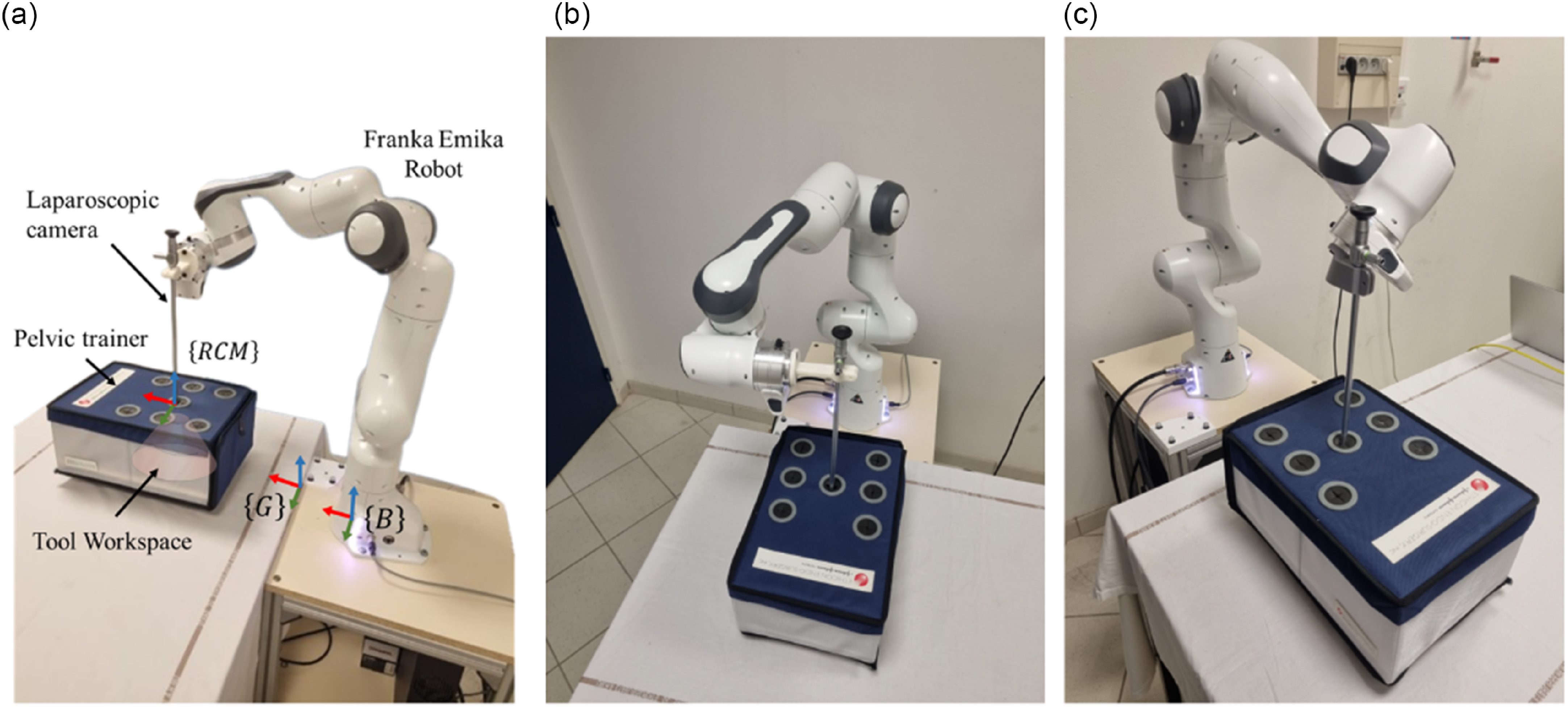
Figure 16. Experimental validation: (a) Robot-assisted camera holder platform setup. Robotic platform configuration (b) Proposed by previous works and (c) Generated by the optimization algorithm.
The validation of the work presented in this study is carried out experimentally on the simulation platform. The placement of the robot’s base is defined with respect to a global referential G where all the other parameters are prescribed such as the patient location (represented by a pelvic trainer in our simulation), the position of the incision point RCM, and the surgical camera workspace. An experimental investigation was conducted to compare an existing solution to the design vector X of the platform proposed in previous work [Reference Sandoval, Laribi, Faure, Breque, Richer and Zeghloul6]. The author proposes a robotic assistant platform configuration to pretend a good system ergonomics and to increase the working space of the task. Although an optimization study has not been conducted, the solution depicted in Fig. 16b was selected using qualitative analysis to ensure that the robot is always at a safe distance from its joint stops.
On the other hand, Fig. 16c represents the optimal solution obtained by the optimization algorithm that aims to improve the statics and dynamic behavior of the robot and to satisfy the different criteria such as maximizing the accessibility index of the robot, maximizing the manipulability during the task and minimizing the energy consumption of the robot during the surgical application.
A visual representation of the reachability of the surgical camera’s constrained workspace is displayed to allow for a comparison of the different solutions that have been suggested. The laparoscope is used to navigate a cone with an entry point RCM at the top and a 60-degree opening angle by inserting it through a small incision made in the patient’s abdominal surface.
In the first instance, a comparison of the two proposed solutions is carried out in order to examine the kinematic capabilities for each platform configuration within the boundaries of the task workspace. The results of this test are shown in Tables II and III, where the camera’s orientation is changed until the cone’s limits define the area over which the laparoscope sweeps. Table II illustrates a comparison between the optimal solution and the solution selected in a previous work for a change of the orientation of the surgical camera according to the x-axis of global reference. The validation parameters of this static test are limited by the reachability index (RI) and the manipulability index (MI) for each pose, where
![]() $\alpha$
takes as a value of –30 degrees the lower limit of the space, the center pose of the workspace, and + 30 degrees as an upper limit. The results of our static criteria demonstrate that the various solutions have good task accessibility, as demonstrated by an index of accessibility greater than 98%, but the solution chosen by the optimization algorithm has an advantage at the manipulability level; the test represents an index of manipulability greater than 0.1 for a variation in orientation along the x-axis compared to an index ranging between 0.07 and 0.085 for the solution proposed in the previous work.
$\alpha$
takes as a value of –30 degrees the lower limit of the space, the center pose of the workspace, and + 30 degrees as an upper limit. The results of our static criteria demonstrate that the various solutions have good task accessibility, as demonstrated by an index of accessibility greater than 98%, but the solution chosen by the optimization algorithm has an advantage at the manipulability level; the test represents an index of manipulability greater than 0.1 for a variation in orientation along the x-axis compared to an index ranging between 0.07 and 0.085 for the solution proposed in the previous work.
Table II. Laparoscopic camera’s x-axis orientation deviation compared between the existing (previous) and the optimized problem solution.

Table III. Laparoscopic camera’s y-axis orientation deviation comparison between the existing (previous) and the optimized solution.

Table III represents the variation of the orientation of the camera according to the second tilt angle, a variation according to the y-axis of the global reference frame was carried out until the limit of the working space of the spot at
![]() $\beta$
equal
$\beta$
equal
![]() $\pm$
30 degrees. This test shows an equal behavior for the two configurations proposed at the level of upper limit
$\pm$
30 degrees. This test shows an equal behavior for the two configurations proposed at the level of upper limit
![]() $\beta =30$
degrees. Whereas at the lower limit
$\beta =30$
degrees. Whereas at the lower limit
![]() $\beta =-30$
degrees, the solution of the optimization algorithm has a good RI at 95.625%, and an average MI equal to 0.0813. However, the reference solution has a good MI, but a very poor RI equals to 87.875%.
$\beta =-30$
degrees, the solution of the optimization algorithm has a good RI at 95.625%, and an average MI equal to 0.0813. However, the reference solution has a good MI, but a very poor RI equals to 87.875%.
A dynamic study is established for the different configurations to properly criticize their behavior. A complex trajectory that serves to sweep all the workspace of the surgical task was tested. This experimental validation simulates the star trajectory proposed in section 4 where the optimization criteria are illustrated in Figs. 17, 18, and 19.

Figure 17. Reachability index comparison of the optimal and the proposed solution for the same trajectory.

Figure 18. Manipulability index comparison of the optimal and the proposed solution for the same trajectory.

Figure 19. Power conception comparison of the optimal and the proposed solution for the same trajectory.
Figure 17 shows the robot end-effector reachability index versus the desired trajectory execution times for the tow solutions. This analysis shows that the reachability index is always greater than 98% along the trajectory for the optimization algorithm result. On the other hand, the previous solution represented by the previous work shows significant variations in the accessibility index, demonstrating that the robot’s end-effector can pass through regions with low reachability.
The manipulability index of the simulation platform is presented in Fig. 18 for the optimal solution and the proposed solution on the same trajectory covering the abdominal task workspace. The validation test results indicate that the previous solution exhibits an average value of 0.0804 and a manipulability index variation that falls below 0.06. In contrast, the optimal solution demonstrates a reasonable manipulability curve over time, with an average value of 0.0917 along the trajectory, representing a 14% improvement due to the new configuration.
To validate the dynamic behavior of the robotic platform, a visualization of the power consumed by the actuators of the robot as explained in Eq. 15 is displayed in Fig. 19. This criterion highlights the energy consumed by the robot as well as the variation of torque generated by motors. The optimal solution presents a minimal power variation during the trajectory with a maximum amplitude of 12.61 W and an average power of 3.35 W. Unlike the proposed configuration presents a maximum power of 20.86 W and an average power of 6.07 W. indicating a 43% reduction in mean power consumption and a lower maximum power due to the new configuration.
6. Conclusion
The optimal placement of a redundant robot has always been a challenge for researchers, especially in tasks where precision and dexterity are critical. In the realm of minimally invasive surgical procedures, such as laparoscopic surgery, achieving the safe and precise execution of a specific surgical task while satisfying the RCM and additional constraints is of the uttermost importance. This paper presents a novel technique to improve laparoscopic robotic platform performance by simultaneously optimizing the robot base placement and the tool mounting orientation. The proposed technique enhances the kinematic and dynamic performance of the robot-assisted camera holder system, providing surgeons more control and precision during challenging laparoscopic surgeries.
The developed platform optimization technique exploits the capacity map of a redundant Franka Emika robot with 7 DoF and implements the task constraints to identify the best design vector define the base placement and the tool assembly orientation. To determine the optimal solution, a multiobjective algorithm is used to improve the task’s manipulability and accessibility index, while maintaining the system’s compactness. This problem is solved using a genetic algorithm method, thanks to its ability to explore vast search spaces. The results obtained are presented as a Pareto front which present the best compromise between the different objectives. A selection technique has been implemented to identify a suitable solution. This method is intended to implement a new selection criterion that minimizes the power generated by the robot’s actuators and reduces the variation in joint torques. An evaluation trajectory was simulated for the optimization algorithm solutions, and according to the last criterion a classification of the results was performed, leading to the selection of the solution with the minimum power variation.
The experimental results were used to evaluate the actual robotic system’s performance. Although the simulation environment predicted good performance for the optimized configuration, this experimental validation demonstrates the efficacy of the optimization technique by contrasting it to a solution proposed in a previous work, resulting in a qualitative analysis to verify that the robot operates well within its joint limits. When comparing results for the same task, the results reveal a 2% improvement in the accessibility index and a 14% enhancement in manipulability. Additionally, the dynamic performance criteria led to a 43% reduction in power consumption.
Author contributions
AT, JS, and MAL conceived and designed the study. AT, JS, and MAL conducted data gathering. AT, JS, and AM performed statistical analyses. AT, JS, AM, SL, and SZ reviewed the first draft of the manuscript.
Financial support
This research received specific grants from “The France Excellence Eiffel Scholarship Program” and the international research program founded by CNRS “IRP RACeS”.
Competing interests
The authors declare no competing interests exist.
Ethical standards
None.


