


1. Introduction
The wall-climbing robot, which can adhere to and move on vertical surfaces, is developed to carry out tasks with high risks in dangerous environments instead of workers. It has become increasingly widely used in construction, petrochemicals, nuclear energy, shipbuilding, and other industries [Reference Prados, Hernando, Gambao and Brunete1–Reference Hong, Wang, Yuan and Wang4]. According to the adhesion ways, the wall-climbing robot can be mainly divided into magnetic adhesion [Reference Wang, Zhang, Zhang, Sun and Li5], negative pressure adhesion [Reference Fang, Wang, Cui, Bi, Jiang and Yan6], bionic materials [Reference Kim, Spenko, Trujillo, Heyneman, Santos and Cutkosky7], bionic hook [Reference Liu, Xu, Xu, Li, Chen, Xu, Cheng and Ceccarelli8, Reference Han, Ji, Jiang, Hu and Gorb9], and thrust adhesion [Reference Liang, Gao, Gao, Zhang and Li10]. Among these methods of adhesion, the negative pressure wall-climbing robot is most widely used because it can adapt to different material walls by creating a closed vacuum chamber with a strong adhesion force [Reference Li, Xu and Tam11, Reference Wu, Wang and Hua12].
To increase the utility of the negative pressure wall-climbing robot, a lot of work has been carried out on the improvement of the environment adaptability of the wall-climbing robot, especially for spherical-surface, cross-surface, and cylindrical surface [Reference Zhang, Gao, Li, Wei and Liang13–Reference Ramalingam, Manuel, Elara, Vengadesh, Lakshmanan, Ilyas and James16]. As a typical structure, cylindrical surfaces are ubiquitous in various industries, such as the circular columns on skyscrapers, the cylindrical bridge piers, and the curved surfaces of hydropower station dam conduits. According to the location mode, the wall-climbing robots designed for cylindrical walls can be classified as foot-type and wheel-track type.
For the foot-type wall-climbing robot, there are multiple suction chambers equipped and multiple discrete points of contact with the wall, which can ensure that the robot has good adaptability to the complex environment. Shang used 48 small suction cups to improve the adaptability of the robot on curved surfaces [Reference Shang, Sattar, Chen and Bridge17]. Wang introduced a dual-foot biped robot with a vacuum sucker composed of three flexible hinge suction cups, and the robot can climb and steer on the wind turbine blade [Reference Wang, Feng, Luo, Jin and Wu18]. Amakawa designed a wall-climbing robot comprised of eight mobile adhesion chambers, enabling it to achieve both movements and adhesion on the wings of an aircraft [Reference Amakawa, Yamaguchi, Yamada and Nakamura19]. Parween developed a wall-climbing robot with two suction cups that can move freely on a single axis, allowing the robot to adhere to planes and curved surfaces [Reference Parween, Wen and Elara20]. The foot-type wall-climbing robot is flexible and has strong adaptability to the wall and can even realize wall transition, obstacle crossing, and other functions [Reference Li, Li, Tam and Xu21–Reference Zhang, Yang, Yan, Zhou, Zou and Gu23]. On the other hand, an increased number of suction chambers leads to complexity and significant increases in the size and weight of the robot. Moreover, the locomotion of robots on cylindrical surfaces relies on the collaborative movement of each mechanism, which leads to low movement efficiency.
For the wheel-track wall-climbing robot, one suction chamber is usually equipped for adhesion and wheels or tracks are equipped for locomotion. Yang designed a robot with a suction chamber that had a flexible skirt to satisfy the surface implementation of the robot [Reference Yang, Li, Feng, Yang, Chang, Jiang and Xiao24]. I. M. Koo proposed a double-layer sealing mechanism, which is composed of a straight inner layer and a flexible bending layer. The outer bending layer can deform under the action of negative pressure and has good contact with the wall surface to ensure reliable sealing [Reference Koo, Trong, Lee, Moon, Koo, Park and Choi25]. Yang et al. proposed a two-stage passive compliant adsorption mechanism for wall-climbing robots, which can improve the adaptability of high curvature walls [Reference Yang, Song, Wang, Chang, Jing and Deng14]. The wheel-track wall-climbing robots are proposed for climbing on planes and show the characteristics of fast-moving [Reference Fang, Wang, Cui, Bi, Jiang and Yan6, Reference Zhong, Xu, Xiao and Lu26–Reference Zhao, Li and Bai29]. However, when the robot climbs on a cylindrical wall, some wheels and tracks are suspended, resulting in unstable movement or even failure. In addition, the contact between the adsorption cavity and the circular surface will also decrease.
In this article, a robot with an omnidirectional locomotion module and compliant adjusting module was designed and the analyses of the robot were carried out. The compliant adjusting module makes good contact between the suction chamber and a cylindrical surface and increases the adhesion performance of the robot on the cylindrical wall. With the omnidirectional locomotion mode, the robot can traverse the cylindrical wall without steering and prevent the detachment between the suction chamber and cylindrical wall caused by steering.
The following sections of this article are structured as follows: Section 2 provides an analysis of the traditional wall-climbing robot locomotion mode on a cylindrical wall. Section 3 introduces the omnidirectional locomotion mode and the overall mechanical structure of the robot. In Section 4, the safety adhesion model of the robot in quasi-static motion on cylindrical walls was developed. In Section 5, a prototype of the proposed robot was introduced, and experimental results were given to verify its unique characteristics of omnidirectional locomotion.
2. Analysis of wheel-track wall-climbing robot on a cylindrical wall
The conventional wheel-track wall-climbing robot performs two types of movements: steering and straight movement. During straight movement, the robot stays stable. But its state changes during steering, which can cause possibly instability in adhesion and mobility. In this section, the steering stable of a two-wheeled wall-climbing robot on a cylindrical wall will be analyzed.
2.1. Kinematics
The two-wheeled wheel-track wall-climbing robot is shown in Fig. 1(a). There are two wheels and a clothed foam skirt on this robot. The position between the clothed foam skirt and the wheels is relatively fixed. The clothed foam skirt is elastic-deform and has good contact with the wall. In Fig. 1(a),
 $\{b\}$
is the robot frame, located in the center of the robot, and
$\{b\}$
is the robot frame, located in the center of the robot, and
 $\{s\}$
is the fixed frame, located in the center of the cylindrical wall. The Z-axis of the robot frame
$\{s\}$
is the fixed frame, located in the center of the cylindrical wall. The Z-axis of the robot frame
 $\{b\}$
and the fixed frame
$\{b\}$
and the fixed frame
 $\{s\}$
are coincident. The steering angle
$\{s\}$
are coincident. The steering angle
 $\theta _2$
is defined as the angle between the X-axis of the robot frame
$\theta _2$
is defined as the angle between the X-axis of the robot frame
 $\{b\}$
and the X-axis of the fixed frame
$\{b\}$
and the X-axis of the fixed frame
 $\{s\}$
.
$\{s\}$
.
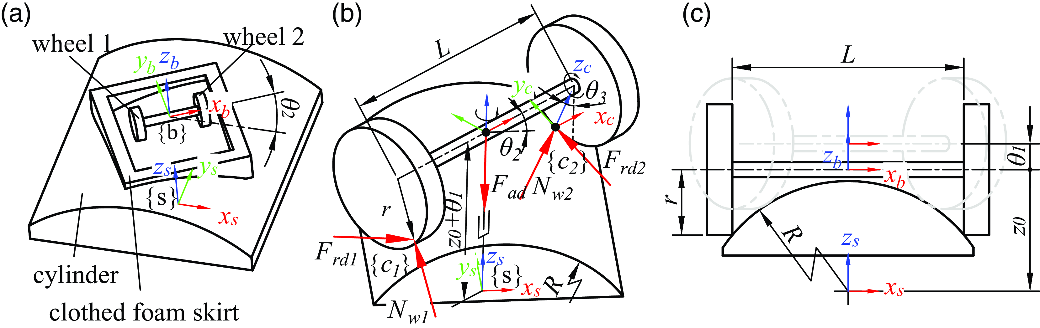
Figure 1. Locomotion of the two-wheeled wheel-track wall-climbing robot and forces acting on the wheels. (a) The robot steers on a cylinder at an angle of
 $\theta _2$
. (b) The locomotion of the robot can be equivalent to a PRR mechanism. There are driving force
$\theta _2$
. (b) The locomotion of the robot can be equivalent to a PRR mechanism. There are driving force
 $F_{rd1}$
,
$F_{rd1}$
,
 $F_{rd2}$
, normal force
$F_{rd2}$
, normal force
 $N_{w1}$
,
$N_{w1}$
,
 $N_{w2}$
and adhesion force
$N_{w2}$
and adhesion force
 $F_{ad}$
acting on wheels. (c) The initial state of the robot on a cylinder.
$F_{ad}$
acting on wheels. (c) The initial state of the robot on a cylinder.
 $z_0$
is the distance between the two frames along the Z-axis in the initial state.
$z_0$
is the distance between the two frames along the Z-axis in the initial state.
 $\theta _1$
represents the prismatic extension/retraction by the joint 1.
$\theta _1$
represents the prismatic extension/retraction by the joint 1.
The steering of the robot on the cylindrical wall can be equivalent to the movement of a PRR mechanism, as shown in Fig. 1(b). Where the joint
 $1$
is prismatic, joint
$1$
is prismatic, joint
 $2$
and joint
$2$
and joint
 $3$
are revolute pairs. Choose the fixed frame
$3$
are revolute pairs. Choose the fixed frame
 $\{s\}$
and the contact point frame
$\{s\}$
and the contact point frame
 $\{c_2\}$
as indicated in the figure, and express homogeneous transformations in terms of the fixed frame. The forward kinematics from
$\{c_2\}$
as indicated in the figure, and express homogeneous transformations in terms of the fixed frame. The forward kinematics from
 $\{s\}$
to
$\{s\}$
to
 $\{c_2\}$
can be obtained [Reference Lynch and Park30]:
$\{c_2\}$
can be obtained [Reference Lynch and Park30]:
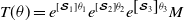 \begin{equation}{\boldsymbol T} (\theta )=e^{\left [{\boldsymbol{\mathcal{S}}}_1 \right ]\theta _1 } e^{\left [{\boldsymbol{\mathcal{S}}}_2 \right ]\theta _2 } e^{\left [{\boldsymbol{\mathcal{S}}}_3 \right ]\theta _3 }{\boldsymbol M} \end{equation}
where
 $\theta _1$
,
$\theta _1$
,
 $\theta _2$
, and
$\theta _2$
, and
 $\theta _3$
are joint variables.
$\theta _3$
are joint variables.
 $\theta _1$
is a linear variable that represents the prismatic extension/retraction by the joint
$\theta _1$
is a linear variable that represents the prismatic extension/retraction by the joint
 $1$
. The screw axis of joint
$1$
. The screw axis of joint
 $1$
is
$1$
is
 ${{\boldsymbol{\mathcal{S}}} _1}=(0,0,0,0,0,1)^{\textrm{T}}$
.
${{\boldsymbol{\mathcal{S}}} _1}=(0,0,0,0,0,1)^{\textrm{T}}$
.
 $\theta _2$
and
$\theta _2$
and
 $\theta _3$
are angular variables that represent the joint angles of the joint
$\theta _3$
are angular variables that represent the joint angles of the joint
 $2$
and joint
$2$
and joint
 $3$
, respectively. Tt’s screw axis are
$3$
, respectively. Tt’s screw axis are
 ${{\boldsymbol{\mathcal{S}}} _2}=(0,0,1,0,0,0)^{\textrm{T}}$
and
${{\boldsymbol{\mathcal{S}}} _2}=(0,0,1,0,0,0)^{\textrm{T}}$
and
 ${{\boldsymbol{\mathcal{S}}} _3}=(1,0,0,0,z_0,0)^{\textrm{T}}$
, respectively.
${{\boldsymbol{\mathcal{S}}} _3}=(1,0,0,0,z_0,0)^{\textrm{T}}$
, respectively.
 $z_0$
is the distance between the two frames along the Z-axis in the initial state,
$z_0$
is the distance between the two frames along the Z-axis in the initial state,
 $z_0=\sqrt{\left (R^2 - L^2/4\right ) } + r$
.
$z_0=\sqrt{\left (R^2 - L^2/4\right ) } + r$
.
 $L$
is the distance between two wheels,
$L$
is the distance between two wheels,
 $r$
is the radius of the wheel,
$r$
is the radius of the wheel,
 $R$
is the radius of the cylindrical wall.
$R$
is the radius of the cylindrical wall.
 $M$
is the contact point frame
$M$
is the contact point frame
 $\{c_2\}$
configuration when the robot is in its zero position.
$\{c_2\}$
configuration when the robot is in its zero position.
 $M$
can be obtained as
$M$
can be obtained as
 \begin{equation} M= \begin{bmatrix} 1 & 0 & 0 & L/2 \\ 0 & 1 & 0 & 0 \\ 0 & 0 & 1 & z_0-r \\ 0 & 0 & 0 & 1 \\ \end{bmatrix} \end{equation}
Two geometric constraints as follows must be satisfied when the wheel contacts with the cylindrical wall.
-
Constraint I: Contact point on the cylindrical surface. The location of the contact point between the cylindrical wall and wheel 2 is
(3)Thus, this condition can be expressed mathematically as \begin{equation}{\boldsymbol p}_{c2}= \begin{bmatrix} p_{c2x} \\ p_{c2y} \\ p_{c2z} \\ \end{bmatrix} ={\boldsymbol T} (\theta ) \begin{bmatrix} 0 \\ 0 \\ 0 \\ 1 \end{bmatrix} \end{equation}
(4)
\begin{equation}{p_{c2x}}^2+{p_{c2z}}^2 =R^2 \end{equation}
\begin{equation}{\boldsymbol p}_{c2}= \begin{bmatrix} p_{c2x} \\ p_{c2y} \\ p_{c2z} \\ \end{bmatrix} ={\boldsymbol T} (\theta ) \begin{bmatrix} 0 \\ 0 \\ 0 \\ 1 \end{bmatrix} \end{equation}
(4)
\begin{equation}{p_{c2x}}^2+{p_{c2z}}^2 =R^2 \end{equation}
-
Constraint II: The wheel is tangent to the cylindrical wall. As this condition is satisfied, it can be demonstrated that the normal direction of the cylindrical surface at the contact point is perpendicular to the tangent direction of the wheel. The tangent direction of the wheel is the Y-axis of
$\{c_2\}$
, and can be expressed as(5)The normal direction of the cylindrical tangent plane is
\begin{equation}{\boldsymbol n}_2= \begin{bmatrix} n_{2x} \\ n_{2y} \\ n_{2z} \\ \end{bmatrix} ={\boldsymbol T} (\theta ) \begin{bmatrix} 0 \\ 1 \\ 0 \\ 0 \end{bmatrix} \end{equation}
${\boldsymbol n}_{w2}= (p_{c2x}/R,0,p_{c2z}/R)^{\textrm{T}}$
. This condition can be expressed as follows(6)
\begin{equation}{{\boldsymbol n}_{w2}}^{\textrm{T}}{\boldsymbol n}_2 =0 \end{equation}


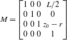
So, the equation (4) and (6) can be resolved through the numerical method. It is obtained the relationship between
 $\theta _1$
,
$\theta _1$
,
 $\theta _2$
, and
$\theta _2$
, and
 $\theta _3$
as shown in Fig. 2. During steering,
$\theta _3$
as shown in Fig. 2. During steering,
 $\theta _1$
increases with
$\theta _1$
increases with
 $\theta _2$
, leading to an increase in the distance between the suction chamber and cylindrical wall. This may result in the detachment of the clothed foam skirt from the wall.
$\theta _2$
, leading to an increase in the distance between the suction chamber and cylindrical wall. This may result in the detachment of the clothed foam skirt from the wall.
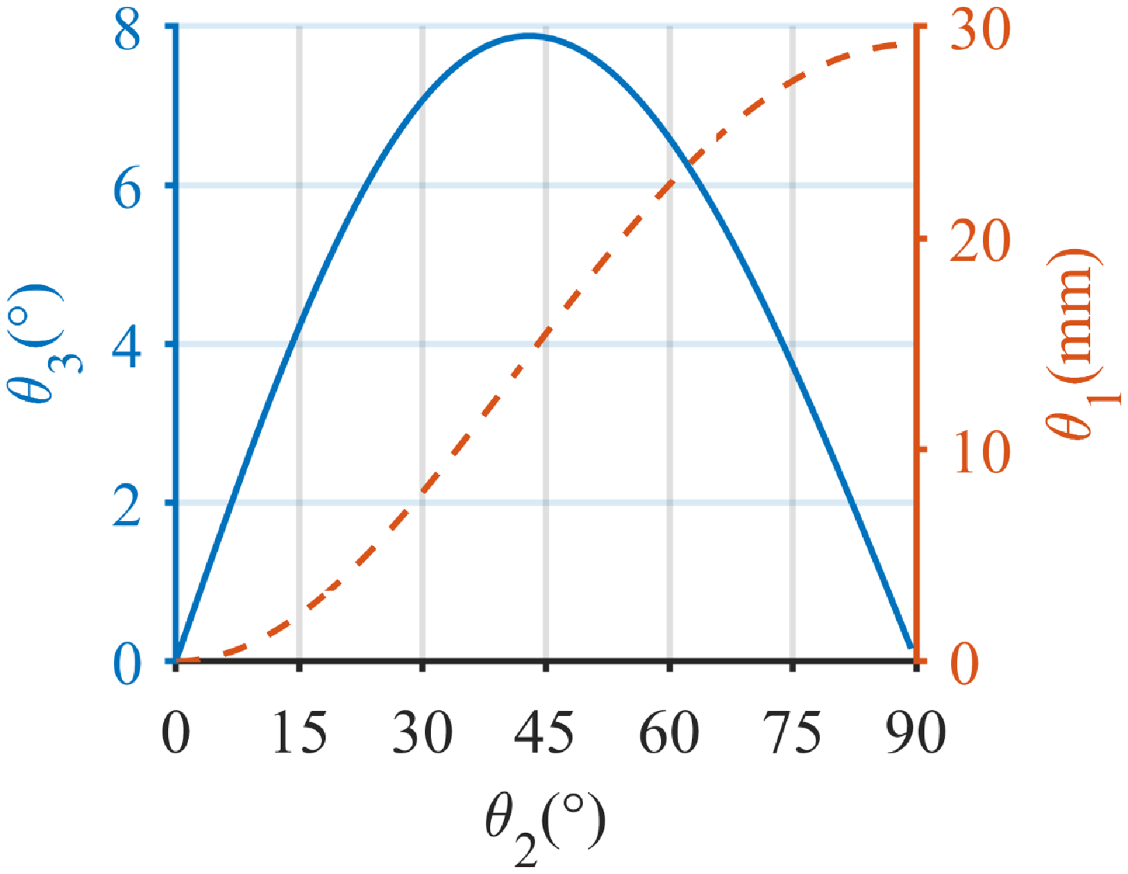
Figure 2. The geometric relationship of the equivalent mechanism during steering. In this case, the parameters are set as
 $R=700\text{mm}$
,
$R=700\text{mm}$
,
 $L=400\text{mm}$
,
$L=400\text{mm}$
,
 $r=75\text{mm}$
.
$r=75\text{mm}$
.
2.2. Adhesion failure on the cylindrical wall
Steering causes the clothed foam skirt to detach from the wall, reducing the contact area between the clothed foam skirt and the cylindrical wall. If the contact area cannot form a closed area, the adhesion fails. In this part, we will analyze the contact between the clothed foam skirt and the cylindrical wall. The contact situation between the skirt and the cylindrical wall is shown in Fig. 3.

Figure 3. Contact situation between the clothed foam skirt and cylindrical wall during robot steering. (a) Is the aerial view and (b) Is the frontal view.
It is assumed that in the initial state, the skirt has an ideal contact with the cylindrical wall, which is that all faces of the clothed foam skirt are just in contact with the cylindrical wall and can be expressed as follows:
 \begin{equation} R^2-{\left (z_0-h_{1}-h_{2}\right )}^2=\frac{{L_1}^2}{4} \end{equation}
where
 $h_1$
is the distance between
$h_1$
is the distance between
 $\{b\}$
and the clothed foam skirt, and
$\{b\}$
and the clothed foam skirt, and
 $h_2$
is the thickness of the skirt. When the steering angle is
$h_2$
is the thickness of the skirt. When the steering angle is
 $\theta _2$
, the contact width between the skirt and the cylindrical wall is
$\theta _2$
, the contact width between the skirt and the cylindrical wall is
 \begin{equation} w_2 =2\sqrt{ R^2-{\left (z_0+\theta _1 -h_{1}-h_{2}\right )}^2} \end{equation}
 $w_1$
is the minimum contact width that can ensure a closed contact area. It is calculated as follows according to the geometric relationship from Fig. 3(b).
$w_1$
is the minimum contact width that can ensure a closed contact area. It is calculated as follows according to the geometric relationship from Fig. 3(b).
 \begin{equation} w_1 =(L_1-2b) \cos \theta _2+ (L_2-2b) \sin \theta _2 \end{equation}
Figure 4. The contact width of the skirt
 $w_2$
and the minimum width
$w_2$
and the minimum width
 $w_1$
to ensure effective contact in four cases.
$w_1$
to ensure effective contact in four cases.
Figure 4 illustrates the contact width
 $w_2$
between the skirt and the wall, and the minimum width
$w_2$
between the skirt and the wall, and the minimum width
 $w_1$
required for a closed contact area at steering angle
$w_1$
required for a closed contact area at steering angle
 $\theta _2$
. We know that when the robot is steering, the actual contact width
$\theta _2$
. We know that when the robot is steering, the actual contact width
 $w_2$
decreases sharply and will decrease to
$w_2$
decreases sharply and will decrease to
 $0$
, and the changing trend of the required width is first increasing and then decreasing. To ensure the airtightness of the suction chamber, the contact area must form a sealed space to prevent air leakage. This condition can be expressed as follows: the contact width
$0$
, and the changing trend of the required width is first increasing and then decreasing. To ensure the airtightness of the suction chamber, the contact area must form a sealed space to prevent air leakage. This condition can be expressed as follows: the contact width
 $w_2$
of the skirt must be greater than the minimum width for effective contact
$w_2$
of the skirt must be greater than the minimum width for effective contact
 $w_1$
, that is,
$w_1$
, that is,
 $w_2 \gt w_1$
.
$w_2 \gt w_1$
.
 $\theta _2 ^*$
is defined as the value of the
$\theta _2 ^*$
is defined as the value of the
 $\theta _2$
when the contact width of the skirt
$\theta _2$
when the contact width of the skirt
 $w_2$
is equal to the minimum width
$w_2$
is equal to the minimum width
 $w_1$
. It is obtained that airtightness can only be guaranteed if the steering angle
$w_1$
. It is obtained that airtightness can only be guaranteed if the steering angle
 $\theta _2$
is smaller than
$\theta _2$
is smaller than
 $\theta _2 ^*$
. From adjusting the parameters of
$\theta _2 ^*$
. From adjusting the parameters of
 $L_1$
and
$L_1$
and
 $L_2$
, we can find that the steering angle is always limited to a small range to ensure valid adhesion, which is restricted by the structure of the wheel-track wall-climbing robot. In addition, combined with equations 8 and 9, we can find that the value of
$L_2$
, we can find that the steering angle is always limited to a small range to ensure valid adhesion, which is restricted by the structure of the wheel-track wall-climbing robot. In addition, combined with equations 8 and 9, we can find that the value of
 $w_2$
can be increased by increasing the value of
$w_2$
can be increased by increasing the value of
 $h_1$
and
$h_1$
and
 $h_2$
. The value of
$h_2$
. The value of
 $w_1$
can be decreased by decreasing the value of
$w_1$
can be decreased by decreasing the value of
 $L_1$
and
$L_1$
and
 $L_2$
or increasing the value of
$L_2$
or increasing the value of
 $b$
. This means that increasing the values of
$b$
. This means that increasing the values of
 $h_1$
,
$h_1$
,
 $h_2$
, and
$h_2$
, and
 $b$
or decreasing the values of
$b$
or decreasing the values of
 $l1$
and
$l1$
and
 $L_2$
can improve the adaptability of the robot to the cylindrical surface, that is, reducing the radius of the cylinder to which the robot can adhere. However, it is important to note that reducing the dimensions of the adhesion chamber (
$L_2$
can improve the adaptability of the robot to the cylindrical surface, that is, reducing the radius of the cylinder to which the robot can adhere. However, it is important to note that reducing the dimensions of the adhesion chamber (
 $L_1$
and
$L_1$
and
 $L_2$
) will reduce the adhesion area and further affect the adsorption force.
$L_2$
) will reduce the adhesion area and further affect the adsorption force.
2.3. Force analysis on the wheel
In the Fig. 1(b), the required driving force to steer the robot is
 $F_{rd1}$
and
$F_{rd1}$
and
 $F_{rd2}$
, respectively.
$F_{rd2}$
, respectively.
 $N_{w1}$
and
$N_{w1}$
and
 $N_{w2}$
are normal forces between the wheel and the cylindrical wall.
$N_{w2}$
are normal forces between the wheel and the cylindrical wall.
 $F_{ad}$
is the adhesion force. Under this condition, we think that the stress of the two wheels is the same size,
$F_{ad}$
is the adhesion force. Under this condition, we think that the stress of the two wheels is the same size,
 $N_{w1}=N_{w2}=N_{w}$
,
$N_{w1}=N_{w2}=N_{w}$
,
 $F_{rd1}=F_{rd2}=F_{rd}$
.
$F_{rd1}=F_{rd2}=F_{rd}$
.
The required driving force wrench on the wheel
 $1$
and the wheel
$1$
and the wheel
 $2$
are given by the column vector in the fixed as follows, respectively.
$2$
are given by the column vector in the fixed as follows, respectively.
 \begin{equation}{{\boldsymbol{\mathcal{F}}} _{rd1}} = \begin{bmatrix}{F_{rd}{\boldsymbol p}_{c1} \times{\boldsymbol n}_1} \\ F_{rd}{\boldsymbol n}_1 \end{bmatrix},{{\boldsymbol{\mathcal{F}}} _{rd2}} = \begin{bmatrix}{F_{rd}{\boldsymbol p}_{c2} \times{\boldsymbol n}_2} \\ F_{rd}{\boldsymbol n}_2 \end{bmatrix} \end{equation}
where
 ${\boldsymbol p}_{c1}=\left (-p_{c2x}, -p_{c2y}, p_{c2z}\right )^{\textrm{T}}$
,
${\boldsymbol p}_{c1}=\left (-p_{c2x}, -p_{c2y}, p_{c2z}\right )^{\textrm{T}}$
,
 ${\boldsymbol n}_{1}=\left (-n_{c2x}, -n_{c2y}, n_{c2z}\right )^{\textrm{T}}$
. The normal force wrench on the wheel
${\boldsymbol n}_{1}=\left (-n_{c2x}, -n_{c2y}, n_{c2z}\right )^{\textrm{T}}$
. The normal force wrench on the wheel
 $1$
and the wheel
$1$
and the wheel
 $2$
in the fixed frame are given respectively by the column vector as
$2$
in the fixed frame are given respectively by the column vector as
 \begin{equation}{{\boldsymbol{\mathcal{F}}} _{N1}} = \begin{bmatrix}{N_{w}{\boldsymbol p}_{c1} \times{\boldsymbol n}_{w1}} \\ N_{w}{\boldsymbol n}_{w1} \end{bmatrix},{{\boldsymbol{\mathcal{F}}} _{N2}} = \begin{bmatrix}{N_{w}{\boldsymbol p}_{c2} \times{\boldsymbol n}_{w2}} \\ N_{w}{\boldsymbol n}_{w2} \end{bmatrix} \end{equation}
where
 ${\boldsymbol n}_{w1}=\left (-n_{w2x}, -n_{w2y}, n_{w2z}\right )^{\textrm{T}}$
. The wrench of adhesion force is
${\boldsymbol n}_{w1}=\left (-n_{w2x}, -n_{w2y}, n_{w2z}\right )^{\textrm{T}}$
. The wrench of adhesion force is
 ${{\boldsymbol{\mathcal{F}}} _{ad}} = \left (0,0,0,0,0,-F_{ad}\right )^{\textrm{T}}$
.
${{\boldsymbol{\mathcal{F}}} _{ad}} = \left (0,0,0,0,0,-F_{ad}\right )^{\textrm{T}}$
.
The static equations of the robot during steering can be obtained
 \begin{equation} \sum{\boldsymbol{\mathcal{F}}}:{{\boldsymbol{\mathcal{F}}} _{ad}} +{{\boldsymbol{\mathcal{F}}} _{rd1}} +{{\boldsymbol{\mathcal{F}}} _{rd2}} +{{\boldsymbol{\mathcal{F}}} _{N1}} +{{\boldsymbol{\mathcal{F}}} _{N2}} =0 \end{equation}
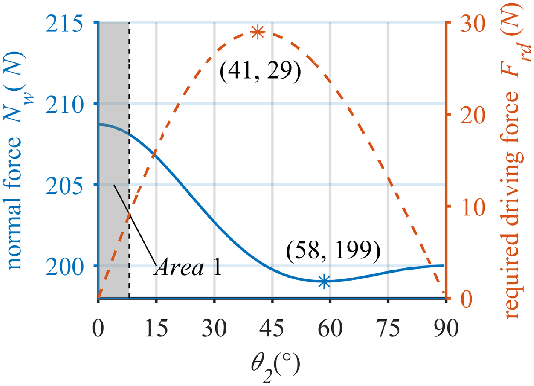
Figure 5. The normal force and the required driving force. In this case, we set
 $F_{ad}=400N$
,
$F_{ad}=400N$
,
 $R=700$
,
$R=700$
,
 $L=400$
,
$L=400$
,
 $r=75$
.
$r=75$
.
The equation (12) contains variables as the normal force
 $N_{w}$
, the driving force
$N_{w}$
, the driving force
 $F_{rd}$
, the adhesion force
$F_{rd}$
, the adhesion force
 $F_{ad}$
, the distance between two wheels
$F_{ad}$
, the distance between two wheels
 $L$
, the radius of the wheel
$L$
, the radius of the wheel
 $r$
, and the radius of the cylindrical wall
$r$
, and the radius of the cylindrical wall
 $R$
. We set
$R$
. We set
 $F_{ad}=400N$
,
$F_{ad}=400N$
,
 $R=700$
,
$R=700$
,
 $L=400$
,
$L=400$
,
 $r=75$
. The relation between normal force
$r=75$
. The relation between normal force
 $N_{w}$
and driving force
$N_{w}$
and driving force
 $F_{rd}$
concerning
$F_{rd}$
concerning
 $\theta _2$
can be obtained by solving it numerically, as shown in Fig. 5. From this result, it is obtained that the amplitude of fluctuation of the normal force is not large, with a trend of first decreasing and then increasing, and the minimum value is taken at
$\theta _2$
can be obtained by solving it numerically, as shown in Fig. 5. From this result, it is obtained that the amplitude of fluctuation of the normal force is not large, with a trend of first decreasing and then increasing, and the minimum value is taken at
 $ \theta _2 = 58 ^{\circ }$
. The required driving force increases first and then decreases, taking the maximum value at
$ \theta _2 = 58 ^{\circ }$
. The required driving force increases first and then decreases, taking the maximum value at
 $\theta _2=41 ^{\circ }$
. For wall-climbing robots, the effect of the adhesion force should increase the normal force between the wheels and the wall as much as possible, ensuring the grip between the wheels and the wall; instead of increasing the resistance in the direction of travel, hindering the movement of the robot, and increasing the driving force required by the robot. The steering angle should be limited to a relatively small range to ensure the mobility of the robot, as shown in
$\theta _2=41 ^{\circ }$
. For wall-climbing robots, the effect of the adhesion force should increase the normal force between the wheels and the wall as much as possible, ensuring the grip between the wheels and the wall; instead of increasing the resistance in the direction of travel, hindering the movement of the robot, and increasing the driving force required by the robot. The steering angle should be limited to a relatively small range to ensure the mobility of the robot, as shown in
 $Area 1$
in Fig. 5.
$Area 1$
in Fig. 5.
In this section, we find that the robot is unable to complete full steering on the cylindrical wall due to the limitations of adhesion and mobility. With the steering,
 $\theta _1$
increases which causes the gap between the clothed foam skirt and cylindrical wall to increase. When the actual contact area cannot satisfy the requirement of a closed suction chamber, it will lead to adhesion failure. The component of the adhesion force along the forward direction causes the increase of the driving force and the decline of the normal force. The increase in the driving force will hinder the mobility of the robot. The decline in the normal force will reduce the grip between the wheels and the wall, and even lead to slip. Due to the limitation of adhesion and locomotion, the robot will not be able to complete the steering on the cylindrical wall. The steering angle between the robot and the cylindrical wall should be kept within a small range to ensure the safety of adhesion and mobility.
$\theta _1$
increases which causes the gap between the clothed foam skirt and cylindrical wall to increase. When the actual contact area cannot satisfy the requirement of a closed suction chamber, it will lead to adhesion failure. The component of the adhesion force along the forward direction causes the increase of the driving force and the decline of the normal force. The increase in the driving force will hinder the mobility of the robot. The decline in the normal force will reduce the grip between the wheels and the wall, and even lead to slip. Due to the limitation of adhesion and locomotion, the robot will not be able to complete the steering on the cylindrical wall. The steering angle between the robot and the cylindrical wall should be kept within a small range to ensure the safety of adhesion and mobility.
3. Mechanical design
3.1. Locomotion design
From the previous section, we know that the wheel-track wall-climbing robot has good performance in both adhesion and locomotion under a small steering angle. Therefore, a robot with omnidirectional locomotion is proposed, which can traverse the cylindrical wall mainly relying on moving along and around the cylindrical wall. The robot can steer in a small steering angle, which is only used to adjust the pose of the robot. The omnidirectional locomotion of the robot is shown in Fig. 6. There are two omni-belt wheels in the robot. Not only does the omni-belt wheel rotate around the central axis of the wheel, but also belts arranged on omni-belt wheels can translate along the central axis. Therefore, the robot can move along the wheel and move vertically along the wheel. In addition, the robot can steer by making the two wheels translate at different speeds. When the robot adheres to a cylindrical wall and the wheel is parallel to the cylindrical wall, because of the omnidirectional locomotion, it can move along the cylindrical wall, move around the cylindrical wall, and steer in a small range, as shown in Fig. 6.

Figure 6. The omnidirectional locomotion of the robot.
3.2. Mobile mechanism
The mechanism diagram of the mobile mechanism is shown in Fig. 7. The mechanism is composed of two omni-belt wheels and a body frame. There are three driving motors in this mechanism. The motor M3 arranged on the body frame drives the omni-belt wheel 1 and the omni-belt wheel 2 to rotate simultaneously to realize the lateral movement of the robot. The motors M1 and M2 are located inside the omni-belt wheel 1 and the omni-belt wheel 2 respectively to realize the longitudinal movement of the robot and steering in a little range.

Figure 7. The diagram of the mobile mechanism.
The structure of the omni-belt wheel is shown in Fig. 8. There are ten outer synchronous pulleys at each end of the omni-belt wheel. Every five synchronous pulleys are connected in series through gimbal couplings. When one of them rotates, the other four will rotate together. The wheel includes eight short synchronous belts and two long synchronous belts. The short synchronous belt meshes with two outer synchronous pulleys. The long synchronous belt meshes with one inner synchronous pulley and two outer synchronous pulleys, constituting a system of three synchronous pulleys. When the motor rotates, two inner synchronous pulleys can rotated together through gear transmission. Then, the long synchronous belt meshed with the inner synchronous pulley drives the outer synchronous pulley to rotate. All synchronous belts can be driven to move in the same direction along the wheel. At least one or two of the ten timing belts are in contact with the wall during the operation of the wall-climbing robot. Then, the robot will move in the direction opposite to the belt movement.

Figure 8. The structure of omni-belt wheel.
3.3. Suction mechanism
The adhesion principle of a negative pressure wall-climbing robot is based on creating a pressure difference between the suction chamber and the outside air. This is achieved through a negative pressure generator which generates a lower pressure in the suction chamber compared to the outside air. The adhesion force is created due to this pressure difference, which ensures that the robot stays tightly affixed to the wall. However, if there is any gap between the suction chamber and the wall, the adhesion will fail. Therefore, it is important to maintain stable contact for the adhesion to be reliable.
A suction mechanism with compliant adjusting is designed to ensure the reliability of adhesion when the robot adheres to the cylindrical wall [Reference Yang, Song, Wang, Chang, Jing and Deng14, Reference Song, Yang, Chang, Yuan and Lin31]. The suction mechanism is shown in Fig. 9. There are springs arranged between the upper suction chamber and the lower suction chamber. Springs provide a force to the lower suction chamber, moving it away from the upper suction chamber. Therefore, the lower suction chamber moves toward the wall surface to avoid the detachment of the clothed foam skirt from the cylindrical wall. Moving between the lower and upper suction chambers allows the suction mechanism to be better adapted to cylindrical surfaces of different diameters as well as to the robot’s steering on the cylindrical surfaces. The clothed foam skirt shape is a rectangular ring, which is composed of soft foam wrapped with impermeable and wear-resistant parachute cloth. When it is in contact with the cylindrical wall, the deformation occurs to fit the wall contour and ensure the reliability of the seal.

Figure 9. The diagram of the suction mechanism.
Figure 10 shows the suction mechanism adheres to a cylindrical surface. The distance between the wheel and the upper suction chamber is constant. The movement between the upper suction chamber and the lower suction chamber ensures contact between the clothed foam skirt and the cylindrical surface. The clothed foam deforms to fit the cylindrical surface because of the loads. The reliability of adhesion on the cylindrical surface is effectively ensured by the combined effect of the movement between the upper suction chamber and the lower suction chamber and the deformation of the clothed foam skirt. During the movement of the robot, there is a relative motion between the clothed foam skirt and the cylindrical surface. The mechanism ensures that the clothed foam skirt is in contact with the cylindrical surface to avoid adhesion failure. In addition, the mechanism can effectively control the contact force between the clothed foam skirt and the cylindrical surface by the springs, and reduce the frictional resistance between the skirt and the wall during movement.

Figure 10. The suction mechanism adheres to a cylindrical surface.
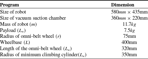
Table I. The main parameters of the robot.
3.4. Overall design
By integrating the compliant adjusting module and the omnidirectional locomotion module, the robot is shown in Fig. 11. The upper suction chamber of the compliant adjusting module is fixed to the body frame of the omnidirectional locomotion module. When the robot climbs on a cylindrical wall and the wheels contact with the wall, the lower suction chamber moves toward the wall surface to Ensure reliable adhesion. The omnidirectional locomotion module makes sure that the robot traverses the cylindrical surface with a small steering angle. The main parameters of the robot are listed in Table I.

Figure 11. The overall design of the robot.
4. Safety adhesion analysis
In this section, we develop the safety adhesion model of the robot in quasi-static motion on cylindrical walls. The minimum adhesion force is obtained through this model, which can keep the robot from slipping and flipping over on cylindrical walls.
As shown in Fig. 12, the robot adheres to a cylindrical wall with an angle
 $\alpha _1$
between the cylindrical wall and the horizontal plane.
$\alpha _1$
between the cylindrical wall and the horizontal plane.
 $\left \{s\right \}$
is the fixed frame whose X-Y plane is parallel to the horizontal plane.
$\left \{s\right \}$
is the fixed frame whose X-Y plane is parallel to the horizontal plane.
 $\left \{b_w\right \}$
is the wall frame whose origin and X-axis coincide with the origin and X-axis of the fixed frame
$\left \{b_w\right \}$
is the wall frame whose origin and X-axis coincide with the origin and X-axis of the fixed frame
 $\left \{s\right \}$
. The angle between Y-axis of
$\left \{s\right \}$
. The angle between Y-axis of
 $\left \{b_w\right \}$
and the Y-axis of
$\left \{b_w\right \}$
and the Y-axis of
 $\left \{b_s\right \}$
is
$\left \{b_s\right \}$
is
 $\alpha _1$
.
$\alpha _1$
.
 $\left \{b_v\right \}$
is the robot frame, located at the center of the robot, whose Y-axis is parallel to the Y-axis of the wall frame
$\left \{b_v\right \}$
is the robot frame, located at the center of the robot, whose Y-axis is parallel to the Y-axis of the wall frame
 $\left \{b_w\right \}$
. The angle between Z-axis of
$\left \{b_w\right \}$
. The angle between Z-axis of
 $\left \{b_v \right \}$
and
$\left \{b_v \right \}$
and
 $\left \{b_w\right \}$
is
$\left \{b_w\right \}$
is
 $\alpha _2$
. There are adhesion force
$\alpha _2$
. There are adhesion force
 ${\boldsymbol F}_{ad}$
, gravity
${\boldsymbol F}_{ad}$
, gravity
 $\boldsymbol G$
, the friction between cylinder and wheels
$\boldsymbol G$
, the friction between cylinder and wheels
 $F_{1 \tau x}$
,
$F_{1 \tau x}$
,
 $F_{1 \tau y}$
,
$F_{1 \tau y}$
,
 $F_{2 \tau x}$
and
$F_{2 \tau x}$
and
 $F_{2 \tau y}$
and the normal forces
$F_{2 \tau y}$
and the normal forces
 $F_{N1}$
and
$F_{N1}$
and
 $F_{N2}$
acting on the robot.
$F_{N2}$
acting on the robot.
 $F_{1 \tau x}$
,
$F_{1 \tau x}$
,
 $F_{2 \tau x}$
,
$F_{2 \tau x}$
,
 $F_{N1}$
and
$F_{N1}$
and
 $F_{N2}$
are distributed loadings.
$F_{N2}$
are distributed loadings.
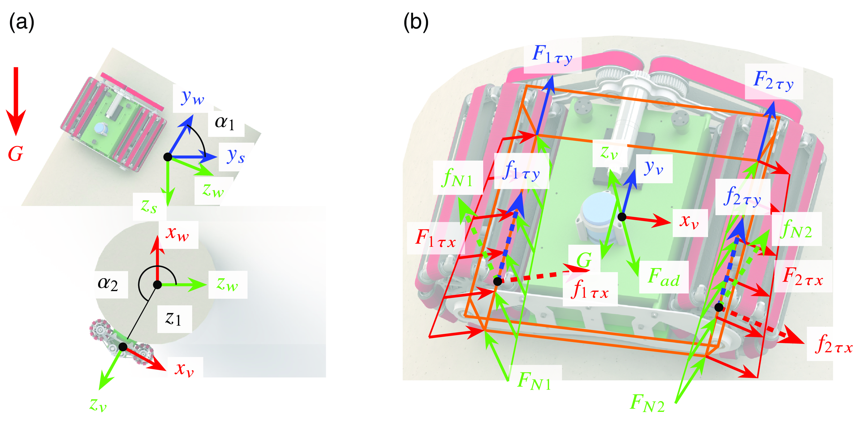
Figure 12. The robot adheres to a cylindrical surface. (a) shows the relationship between frames. (b) shows the forces acting on the robot.
The configuration of the robot frame can be described as
 \begin{equation}{\boldsymbol T }_{sv} = e^{\left [{\boldsymbol{\mathcal{S}}}_1 \right ]\alpha _1 } e^{\left [{\boldsymbol{\mathcal{S}}}_2 \right ]\alpha _2 } \boldsymbol M \end{equation}
where
 ${\boldsymbol{\mathcal{S}}}_1=\left (1,0,0,0,0,0\right )$
and
${\boldsymbol{\mathcal{S}}}_1=\left (1,0,0,0,0,0\right )$
and
 ${\boldsymbol{\mathcal{S}}}_2=\left (0,1,0,0,0,0\right )$
denote the screw axis of the wall frame and the robot frame relative to the fixed frame, respectively.
${\boldsymbol{\mathcal{S}}}_2=\left (0,1,0,0,0,0\right )$
denote the screw axis of the wall frame and the robot frame relative to the fixed frame, respectively.
 $\boldsymbol M$
is the configuration of the robot in its initial position.
$\boldsymbol M$
is the configuration of the robot in its initial position.
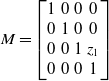 \begin{equation}{\boldsymbol M} = \begin{bmatrix} 1 & 0 & 0 & 0 \\ 0 & 1 & 0 & 0 \\ 0 & 0 & 1 & z_1 \\ 0 & 0 & 0 & 1 \end{bmatrix} \end{equation}
where
 $z_1= \sqrt{\left (R+r\right )^2-L^2/4}$
is the distance between the fixed frame and the robot frame along the Z-axis at
$z_1= \sqrt{\left (R+r\right )^2-L^2/4}$
is the distance between the fixed frame and the robot frame along the Z-axis at
 $\alpha _1=0^\circ$
and
$\alpha _1=0^\circ$
and
 $\alpha _2=0 ^\circ$
.
$\alpha _2=0 ^\circ$
.
 $R$
is the radius of the cylindrical wall.
$R$
is the radius of the cylindrical wall.
The location of gravity of the robot is
 ${\boldsymbol P}_{Gv}$
in the robot frame, also can be expressed as
${\boldsymbol P}_{Gv}$
in the robot frame, also can be expressed as
 ${\boldsymbol P}_{Gs}={\boldsymbol T}_{sv}{\boldsymbol P}_{Gv}$
in the fixed frame. Let gravity denote
${\boldsymbol P}_{Gs}={\boldsymbol T}_{sv}{\boldsymbol P}_{Gv}$
in the fixed frame. Let gravity denote
 ${\boldsymbol G}=\left (0,0,mg\right )^{\textrm{T}}$
in fixed frame. In the fixed frame, the wrench of gravity can be expressed in equation form as follows:
${\boldsymbol G}=\left (0,0,mg\right )^{\textrm{T}}$
in fixed frame. In the fixed frame, the wrench of gravity can be expressed in equation form as follows:
 \begin{equation}{{\boldsymbol{\mathcal{F}}} _{Gs}} = \begin{bmatrix}{{\boldsymbol P}_{Gs} \times{\boldsymbol G}} \\{\boldsymbol G} \end{bmatrix} \end{equation}
In the robot frame, the wrench of gravity can be expressed in equation form as follows:
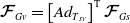 \begin{equation}{\boldsymbol{\mathcal{F}}}_{Gv} = \left [{A{d_{{{\boldsymbol T}_{sv}}}}} \right ]^{\textrm{T}}{\boldsymbol{\mathcal{F}}}_{Gs} \end{equation}
where
 $\left [{A{d_{{{\boldsymbol T}_{sv}}}}} \right ]^{\textrm{T}}$
is the adjoint representation of
$\left [{A{d_{{{\boldsymbol T}_{sv}}}}} \right ]^{\textrm{T}}$
is the adjoint representation of
 ${\boldsymbol T}_{sv}$
.
${\boldsymbol T}_{sv}$
.
The adhesion force is
 ${\boldsymbol F}_{ad}=\left (0,0,-F_{ad}\right )^{\textrm{T}}$
, and the position of the force is at the origin of the robot system, so the wrench of adhesion force can be expressed as follows in the robot frame.
${\boldsymbol F}_{ad}=\left (0,0,-F_{ad}\right )^{\textrm{T}}$
, and the position of the force is at the origin of the robot system, so the wrench of adhesion force can be expressed as follows in the robot frame.
 \begin{equation}{\boldsymbol{\mathcal{F}}}_{adv} = \begin{bmatrix} 0 \\{{{\boldsymbol F}_{ad}}} \end{bmatrix} \end{equation}
The normal forces
 $F_{N1}$
and
$F_{N1}$
and
 $F_{N2}$
are assumed to be linearly distributed loadings, and the slopes are equal. we can set
$F_{N2}$
are assumed to be linearly distributed loadings, and the slopes are equal. we can set
 $F_{N1}=ky+n_1$
and
$F_{N1}=ky+n_1$
and
 $F_{N2}=ky+n_2$
. We can replace the distributed loadings of
$F_{N2}=ky+n_2$
. We can replace the distributed loadings of
 $F_{N1}$
and
$F_{N1}$
and
 $F_{N2}$
with single equivalent resultant forces
$F_{N2}$
with single equivalent resultant forces
 $f_{N1}$
and
$f_{N1}$
and
 $f_{N2}$
at
$f_{N2}$
at
 ${{\boldsymbol r}_1}=\left (r_{1x},r_{1y},r_{1z}\right )^{\textrm{T}}$
,
${{\boldsymbol r}_1}=\left (r_{1x},r_{1y},r_{1z}\right )^{\textrm{T}}$
,
 ${{\boldsymbol r}_2}=\left (r_{2x},r_{2y},r_{2z}\right )^{\textrm{T}}$
. Using the geometric relation of contact point,
${{\boldsymbol r}_2}=\left (r_{2x},r_{2y},r_{2z}\right )^{\textrm{T}}$
. Using the geometric relation of contact point,
 ${\boldsymbol r}_1$
and
${\boldsymbol r}_1$
and
 ${\boldsymbol r}_2$
can be obtained as follows in the robot frame.
${\boldsymbol r}_2$
can be obtained as follows in the robot frame.
 \begin{align}{{\boldsymbol r}_1} = & \displaystyle\begin{bmatrix}{ - \frac{{RL}}{{2(R + r)}}} &{r_{1y}} &{ - \frac{{r{z_1}}}{{R + r}}} \end{bmatrix}^T \end{align}
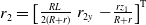 \begin{align}{{\boldsymbol r}_2} = & \displaystyle\begin{bmatrix}{ \frac{{RL}}{{2(R + r)}}} & r_{2y} &{ - \frac{{r{z_1}}}{{R + r}}} \end{bmatrix}^{\textrm{T}} \end{align}
There are the following relationships between normal force and resultant force:
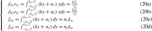 \begin{align} \qquad\qquad\qquad\qquad\qquad\qquad\begin{cases} &f_{N1}r_{1y} = \int _{ - L_w/2}^{L_w/2}{\left ({ky +{n_1}} \right )ydy} = \frac{{k{L_w^3}}}{{12}} \qquad\qquad\qquad\qquad\qquad\qquad\text{(20a)}\\ &f_{N2}r_{2y} = \int _{ - L_w/2}^{L_w/2}{\left ({ky +{n_2}} \right )ydy} = \frac{{k{L_w^3}}}{{12}} \qquad\qquad\qquad\qquad\qquad\qquad\text{(20b)}\\ & f_{N1} = \int _{ - L_w/2}^{L_w/2}{\left ({ky +{n_1}} \right )dy} ={n_1}L_w \quad\qquad\qquad\qquad\qquad\qquad\qquad\text{(20c)}\\ &f_{N2} = \int _{ - L_w/2}^{L_w/2}{\left ({ky +{n_2}} \right )dy} ={n_2}L_w \qquad\qquad\qquad\qquad\qquad\qquad\quad\text{(20d)}\end{cases} \nonumber\end{align}
where
 $L_w$
is the length of the omni-belt wheel. It can be found that equation (20a) is equal to equation (20b). Then we can get the relationship between
$L_w$
is the length of the omni-belt wheel. It can be found that equation (20a) is equal to equation (20b). Then we can get the relationship between
 $r_{1y}$
and
$r_{1y}$
and
 $r_{2y}$
as follows:
$r_{2y}$
as follows:
 \begin{equation} \frac{r_{1y}}{r_{2y}}= \frac{f_{N2}}{f_{N1}} \end{equation}
In a similar way, we can replace the
 $F_{1\tau x}$
,
$F_{1\tau x}$
,
 $F_{1 \tau y}$
,
$F_{1 \tau y}$
,
 $F_{2 \tau x}$
, and
$F_{2 \tau x}$
, and
 $F_{2 \tau y}$
with
$F_{2 \tau y}$
with
 $f_{1\tau x}$
,
$f_{1\tau x}$
,
 $f_{1 \tau y}$
,
$f_{1 \tau y}$
,
 $f_{2 \tau x}$
, and
$f_{2 \tau x}$
, and
 $f_{2 \tau y}$
, respectively. In the robot system, we can get that the resultant force
$f_{2 \tau y}$
, respectively. In the robot system, we can get that the resultant force
 ${\boldsymbol F}_{1}$
and
${\boldsymbol F}_{1}$
and
 ${\boldsymbol F}_{2}$
acting on wheel 1 and wheel 2 are following, respectively.
${\boldsymbol F}_{2}$
acting on wheel 1 and wheel 2 are following, respectively.
 \begin{equation}{\boldsymbol F} _{1} = \begin{bmatrix}{\frac{{{z_1}}}{{R + r}}} & 0 &{ - \frac{{L/2}}{{R + r}}} \\ 0 & 1 & 0 \\{\frac{{L/2}}{{R + r}}} & 0 &{\frac{{{z_0}}}{{R + r}}} \end{bmatrix} \begin{bmatrix} f_{1\tau x} \\ f_{1 \tau y} \\ f_{N1} \end{bmatrix}, \quad{\boldsymbol F} _{2} = \begin{bmatrix}{\frac{{{z_1}}}{{R + r}}} & 0 &{ \frac{{L/2}}{{R + r}}} \\ 0 & 1 & 0 \\{-\frac{{L/2}}{{R + r}}} & 0 &{\frac{{{z_1}}}{{R + r}}} \end{bmatrix} \begin{bmatrix} f_{2\tau x} \\ f_{2 \tau y} \\ f_{N2} \end{bmatrix} \end{equation}
In the robot system, the wrenches of the resultant force acting between the wheel and wall can be expressed as follows, respectively.
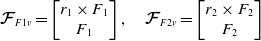 \begin{equation}{\boldsymbol{\mathcal{F}}}_{F1v} = \begin{bmatrix}{{{\boldsymbol r}_1} \times{{\boldsymbol F}_{1}}} \\{{{\boldsymbol F}_{1}}} \end{bmatrix}, \quad{\boldsymbol{\mathcal{F}}}_{F2v} = \begin{bmatrix}{{{\boldsymbol r}_2} \times{{\boldsymbol F}_{2}}} \\{{{\boldsymbol F}_{2}}} \end{bmatrix} \end{equation}
Wheels 1 and 2, being part of the same system, can be assumed to have the same ratio
 $k_\mu$
between the friction and the normal force which can be expressed by the following equation:
$k_\mu$
between the friction and the normal force which can be expressed by the following equation:
 \begin{equation} \frac{{\sqrt{{f_{1\tau x}}^2 +{f_{1\tau y}}^2} }}{f_{N1}} = \frac{{\sqrt{{f_{2\tau x}}^2 +{f_{2\tau y}}^2} }}{f_{N2}} = k_\mu \end{equation}
The sum of the wrench acting on the robot meets:
 \begin{equation} \sum{\boldsymbol{\mathcal{F}}}: \quad{{\boldsymbol{\mathcal{F}}}_{Fadv}} +{{\boldsymbol{\mathcal{F}}}_{Gv}} +{{\boldsymbol{\mathcal{F}}}_{F1v}} +{{\boldsymbol{\mathcal{F}}}_{F2v}} = 0 \end{equation}
Two necessary conditions must be satisfied for safety adhesion when the robot climbs on a cylinder.
-
Non-slipping Conditions: When climbing a cylinder, the robot will slip if the ratio
$k_\mu$
between the friction and the normal force is larger than the coefficient of kinetic friction
$\mu _k$
. The condition that guarantees no slipping is:(26)
\begin{equation} k_\mu \lt \mu _k \end{equation}
-
Non-flipping Over Conditions: When the distributed loading normal force
$F_{N1}$
or
$F_{N2}$
is less than zero, it means that the wheel needs the traction provided by the wall to maintain stability. It is obvious that the wall cannot provide traction to the wheels, which means that the robot will tip over from the wall. Therefore, the condition for do not flip is:(27)
\begin{equation} \left \{ \begin{matrix} F_{N1}\gt 0 \\ F_{N2}\gt 0 \end{matrix} \right . \end{equation}


Figure 13. (a) The adhesion force required by the robot to avoid slipping, when the robot driving the cylindrical surface with a radius of
 $700\text{mm}$
. In this case, we set
$700\text{mm}$
. In this case, we set
 $\mu _k=0.3$
. (b) The minimum value of the distributed loading of
$\mu _k=0.3$
. (b) The minimum value of the distributed loading of
 $F_{N1}$
and
$F_{N1}$
and
 $F_{N2}$
, when the adhesion force in (a) acts on the robot.
$F_{N2}$
, when the adhesion force in (a) acts on the robot.
Solving the equations composed of (21), (24), and (25) using numerical methods to obtain the minimum adhesion force for not slipping, satisfying the non-slipping condition (26). Figure 13(a) illustrates the minimum adhesion force required to prevent slipping. It can be found from this figure that the adhesion force is approximately symmetrically distributed concerning two lines. One of them is the line between
 $\alpha _1=0^\circ$
,
$\alpha _1=0^\circ$
,
 $\alpha _2=180^\circ$
, and
$\alpha _2=180^\circ$
, and
 $\alpha _1=180^\circ$
,
$\alpha _1=180^\circ$
,
 $\alpha _2=0^\circ$
. The other is the line between
$\alpha _2=0^\circ$
. The other is the line between
 $\alpha _1=0^\circ$
,
$\alpha _1=0^\circ$
,
 $\alpha _2=0^\circ$
, and
$\alpha _2=0^\circ$
, and
 $\alpha _1=180^\circ$
,
$\alpha _1=180^\circ$
,
 $\alpha _2=180^\circ$
. The adhesion force required by the robot to avoid slipping takes a maximum value of
$\alpha _2=180^\circ$
. The adhesion force required by the robot to avoid slipping takes a maximum value of
 $416N$
at
$416N$
at
 $\alpha _1 = 106^\circ$
,
$\alpha _1 = 106^\circ$
,
 $\alpha _2 = 178^\circ$
.
$\alpha _2 = 178^\circ$
.
If the adhesion force acting on the robot satisfies the non-slipping condition, we can get the minimum value of distributed loading
 $F_{N1}$
and
$F_{N1}$
and
 $F_{N2}$
, shown in Fig. 13(b). It is obtained that the distributed loading is minimized at the boundary of the feasible region of
$F_{N2}$
, shown in Fig. 13(b). It is obtained that the distributed loading is minimized at the boundary of the feasible region of
 $\alpha _1$
and
$\alpha _1$
and
 $\alpha _2$
, which is
$\alpha _2$
, which is
 $0.02$
, and
$0.02$
, and
 $F_{N1}\gt 0$
and
$F_{N1}\gt 0$
and
 $F_{N2}\gt 0$
are true. So, if the adhesion force acting on the robot satisfies the non-slipping condition, the condition of non-flipping is always satisfied.
$F_{N2}\gt 0$
are true. So, if the adhesion force acting on the robot satisfies the non-slipping condition, the condition of non-flipping is always satisfied.
In summary, the robot needs to be able to generate an adhesion force greater than
 $416N$
to ensure safe adhesion for the cylindrical wall. In this case, we set the coefficient of kinetic friction between the wheel and wall as
$416N$
to ensure safe adhesion for the cylindrical wall. In this case, we set the coefficient of kinetic friction between the wheel and wall as
 $\mu _k=0.3$
, and the radius of the cylindrical wall as
$\mu _k=0.3$
, and the radius of the cylindrical wall as
 $700\text{mm}$
.
$700\text{mm}$
.
5. Prototype and experiments
5.1. Prototype development
Based on the above conclusions, the prototype of the wall-climbing robot was made, as shown in Fig. 14. The suction chamber is made of resin with a density of
 $1.12g/cm^3$
by SLA 3D printing. The track of the omni-belt wheel is a synchronous belt coated with 2 mm rubber on the outer surface, and the rubber coating can increase the friction coefficient between the wheel and the wall surface. The prototype contains four motors. One of them is located at the body frame of the omnidirectional locomotion module with a reducer (160:1) to achieve the lateral movement of the robot. Two motors are located inside the wheel to realize the longitudinal movement of the robot and steering. The other one drives a centrifugal fan that can provide a maximum negative pressure value of
$1.12g/cm^3$
by SLA 3D printing. The track of the omni-belt wheel is a synchronous belt coated with 2 mm rubber on the outer surface, and the rubber coating can increase the friction coefficient between the wheel and the wall surface. The prototype contains four motors. One of them is located at the body frame of the omnidirectional locomotion module with a reducer (160:1) to achieve the lateral movement of the robot. Two motors are located inside the wheel to realize the longitudinal movement of the robot and steering. The other one drives a centrifugal fan that can provide a maximum negative pressure value of
 $18 kPa$
and a maximum flow rate of
$18 kPa$
and a maximum flow rate of
 $1.7 \text{m}^3/\text{min}$
. The size of the robot is
$1.7 \text{m}^3/\text{min}$
. The size of the robot is
 $579 \text{mm} \times 482 \text{mm} \times 224 \text{mm}$
, and the weight is approximately
$579 \text{mm} \times 482 \text{mm} \times 224 \text{mm}$
, and the weight is approximately
 $ 11.7 kg$
.
$ 11.7 kg$
.
Figure 14. Prototype of the wall-climbing robot.
5.2. Suction test
The suction process of the robot on a cylindrical wall is as follows: First, the skirt of the lower suction chamber contacts with the cylindrical wall, and then, the distance between the lower suction chamber and the upper suction chamber shrinks until the wheel contacts with the wall, due to the contact force between the skirt and the wall. Finally, the centrifugal fan starts to operate, the skirt is compressed because of the negative pressure, and the adsorption process completes.
In this subsection, we test the adhesion performance of the wall-climbing robot. We tested the robot payload on a cylindrical wall, as shown in Fig. 15(a). The robot climbed on a cylindrical iron pipe with a radius of
 $0.35\text{m}$
, and it can carry a weight plate with a weight of
$0.35\text{m}$
, and it can carry a weight plate with a weight of
 $7.5kg$
. In addition, we tested the minimum negative pressure for the robot to meet the safety adhesion conditions. The minimum negative pressure required for safety adhesion is
$7.5kg$
. In addition, we tested the minimum negative pressure for the robot to meet the safety adhesion conditions. The minimum negative pressure required for safety adhesion is
 $3.74kPa$
on the vertical board, as shown in Fig 15(b). The minimum negative pressure required for safety adhesion is
$3.74kPa$
on the vertical board, as shown in Fig 15(b). The minimum negative pressure required for safety adhesion is
 $4.42kPa$
on the vertical column surface with a radius of
$4.42kPa$
on the vertical column surface with a radius of
 $0.7\text{m}$
, as shown in Fig 15(c).
$0.7\text{m}$
, as shown in Fig 15(c).
Figure 15. Suction test of the robot.
5.3. Locomotion test
Experiments were carried out to evaluate the robot’s movement performance on cylinders and flat surfaces. We tested the lateral movement of the robot on the plane that is vertical to the horizontal plane, as shown in Fig. 16. In this case, we let motor 1 and motor 2 stay stationary, motor 3 rotate, and the robot moved laterally in the vertical plane at
 $8 \, \text{m/min}$
. We tested the longitudinal of the robot, as shown in Fig. 17. In this case, we let motor 3 stay stationary, motor 1 and motor 2 rotate, and the robot moved longitudinally in the vertical plane at
$8 \, \text{m/min}$
. We tested the longitudinal of the robot, as shown in Fig. 17. In this case, we let motor 3 stay stationary, motor 1 and motor 2 rotate, and the robot moved longitudinally in the vertical plane at
 $6 \, \text{m/min}$
.
$6 \, \text{m/min}$
.
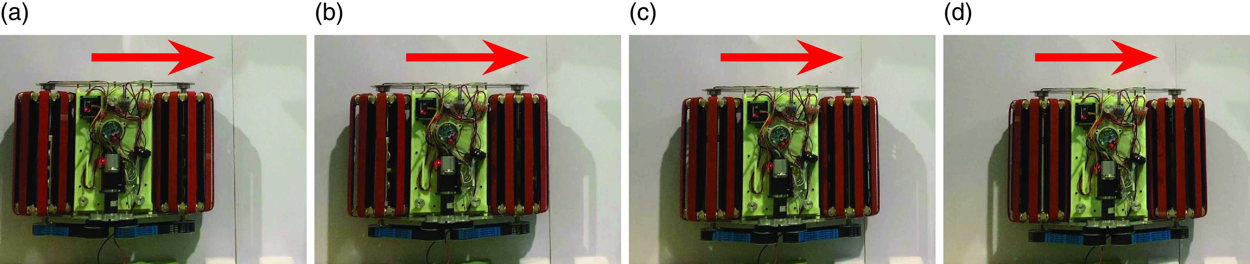
Figure 16. Horizontal movement of the robot on a vertical plane.

Figure 17. Vertical movement of the robot on a vertical plane.
The robot can achieve the locomotion around a column whose radius is
 $0.7\text{m}$
, shown in Fig. 18. There is a gap on the surface of the column, with a width of about
$0.7\text{m}$
, shown in Fig. 18. There is a gap on the surface of the column, with a width of about
 $20\text{mm}$
and a depth of about
$20\text{mm}$
and a depth of about
 $3\text{mm}$
. The clothed foam skirt adapts well to cylindrical walls and can fill the groove of the wall because the skirt consists of flexible foam. So, the robot can still maintain reliable adhesion here. As shown in Fig. 19, The robot can move along the column.
$3\text{mm}$
. The clothed foam skirt adapts well to cylindrical walls and can fill the groove of the wall because the skirt consists of flexible foam. So, the robot can still maintain reliable adhesion here. As shown in Fig. 19, The robot can move along the column.
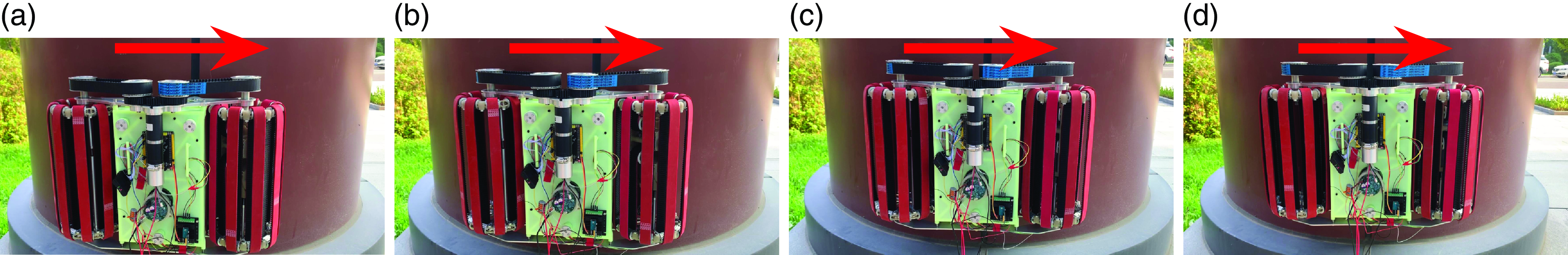
Figure 18. Move around the along the cylindrical wall.

Figure 19. Move along the cylindrical wall.
6. Conclusion
The paper presented a methodology of omnidirectional movement that relies mainly on lateral and longitudinal movements to achieve traversal on cylindrical walls. This methodology makes up for the shortcomings of wheel-track wall-climbing robots in that it cannot complete a full motion on a cylindrical surface. The paper established the safety adhesion model for the wall-climbing robot on cylindrical walls. The prototype was developed to verify the motion and adhesion performance of the robot on cylindrical walls and vertical walls. Benefiting from a methodology of omnidirectional motion and a suction mechanism with compliant adjustment, the prototype can complete the detection of cylindrical surface with a radius greater than
 $350\text{mm}$
.
$350\text{mm}$
.
We believe that the methodology of omnidirectional movement increases the range of feasible applications for climbing robots. In particular, it will increase the robotic detection and manipulation capability to be used in cylindrical environments such as the circular columns on skyscrapers, the cylindrical bridge piers, and the curved surfaces of hydropower station dam conduits.
Supplementary material
The supplementary material for this article can be found at http://dx.doi.org/10.1017/S0263574724000493.
Author contributions
Yuan Chunyang, Chang Yong, and Song Yifeng conceived and designed the study. Yuan Chunyang and Jing Fengren completed the design and fabrication of the prototype. Yuan Chunyang and Lin Song conducted data gathering and texted the performance of the prototype. Yuan Chunyang and Song Yifeng wrote the article.
Financial support
This work was supported by the National Natural Science Foundation of China(Grant No. 52075529)
Competing interests
The authors declare no conflicts of interest exist.
Ethical approval
None.


