1 INTRODUCTION
Recently, many radio interferometers (Taylor, Carilli, & Perley Reference Taylor, Carilli and Perley1999) observing the celestial sources are developed or updated in the world. For example, Nobeyama Radio Heliograph at 17 and 34 GHz (Nakajima, Nishio, & Enome Reference Nakajima, Nishio and Enome1994), Nancay Radio Heliograph at 150, 164, 237, 327, and 410 MHz, and Siberian Solar Radio Telescope at 5.7 GHz (Lesovoi et al. Reference Lesovoi, Altyntsev, Ivanov and Gubin2014) are being used throughout the world. These Radio heliographs cover a few discrete frequency points. There are also some other planned radio heliographs like Brazilian Decimetric array with 15 antennas, the updated Multifrequency Siberian Radioheliograph with 10 antenna prototype, and the Frequency Agile Solar Radiotelescope which has a subsystem Testbed with three antennas under observation. These instruments are providing powerful tools to probe the polarised structures from the observed sources. Now, in China, a heliograph named Chinese Spectral Radioheliograph (CSRH) (Yan et al. Reference Yan, Zhang, Chen, Wang, Liu and Geng2012) is being built, it will observe solar radio emissions (Kane et al. Reference Kane, Sawant, Cecatto, Andrade, Fernandes, Karlicky and Meszarosova2003), radio bursts from the primary energy release sites of the solar energetic events, unique measurements of coronal magnetic fields, shock wave formation, and plasma heating. This instrument consists of two interferometer arrays (CSRH-I and CSRH-II): CSRH-I array is comprised of 40 reflector antennas with 4.5-m dishes over 0.4–2 GHz and CSRH-II array is comprised of 60 reflector antennas with 2-m dishes over 2–15 GHz. All the 100 antennas are arranged in three spiral arms and spread in 3.87 × 10⁴ m2 quiet radio frequency (RF) zone surrounded by small hills (Niu et al. Reference Niu2013). It will output solar radio images with multiple frequencies.
In contrast to other interferometer arrays (Thompson, Moran, & Swenson Reference Thompson, Moran and Swenson2008), CSRH (Yan et al. Reference Yan, Zhang, Wang, Liu, Chen and Ji2008) is intended to be a powerful instrument observing the Sun (Wang et al. Reference Wang2013). It is proposed to obtain images with high spectral resolution using Aperture Synthesis method (Tingay et al. Reference Tingay2013) in a wide bandwidth. Corresponding to the characteristics of radio emissions, the polarisations of radio bursts may vary quickly in milliseconds in solar activities, which are different from other celestial sources. Radio heliograph with good UV coverage could exploit the diagnostic potential of radio emission from the Sun, where the circularly polarised degree of the feed has an effect on the accuracy of solar radio image. When we observe the Sun with different antennas at the same time (Liu et al. Reference Liu, Yan, Zhao and Wang2013), the four stocks parameters I,Q,U,V between two arbitrary antennas should be detected from the instrument. Here, I means total intensity of the wave, Q and U represent the linearly polarised component and V is the circularly polarised component. These parameters could be calculated from the correlations of right and right circular signals, left and left circular signals, right and left circular signals, and left and right circular signals of the Sun. Other Radioheliographs antennas are arranged by the same distances. They do not need to calculate all the Fourier components of each antenna pair. But in our case, we have to detect four times of 1 770 antenna pairs in order to get the correlation of each antenna pair in CSRH-II. This paper is intended to introduce the characteristics of the Eleven feed with designed feeding part. Comparing the feed introduced in the patent (Kildal Reference Kildal2008), the present feed uses more folded dipoles with a compact size and the impedance matching part using a curved balun to cover the frequency range of 2–15 GHz. In addition, this paper introduces how to calculate the polarisation degree measurement of the solar radio signal using antenna HC3 observation (HC3 just represents the number of the antenna).
2 DESIGN AND PERFORMANCE
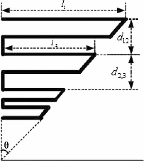
In reference to many ultra wide band feeds, the Eleven feed was chosen and used in CSRH to receive signals coming from the source. The original Eleven feed was designed for Square Kilometer Array telescopes and were clearly introduced in reference Olsson, Kildal, & Weinreb (Reference Olsson, Kildal and Weinreb2006) and Yang et al. (Reference Yang, Pantaleev, Kildal and Helldner2012). Another circular Eleven feed (Jungang et al. Reference Jungang, Jian, Pantaleev and Helldner2013) shows that the measured S11 is below − 8 dB in 14 GHz. However, this performance still does not fulfil the requirement for the solar radio observation with fast changing signals. The specification of the Voltage Standing Wave Ratio (VSWR) of our CSRH feed is below 1.5 (except 10% of frequency band is below 2), the first side lobe of the antenna and feed system specified less than − 15 dB in the whole frequency band. In aim of achieving these parameters, we optimised the feed design. The basic element of the Eleven feed is folded dipoles, it has ‘active region’, this portion is radiating and receiving radiation efficiently and it varies with frequencies. The longest element is active corresponding to the lowest frequency, the shortest element is designed by the highest frequency. Figure 1 shows the half log-periodic geometry of this design, l represents the half wavelength of the folded dipole, d represents the separation between two adjacent folded dipoles, σ is known as the ‘relative spacing constant’ and along with τ determines the angle of the antenna’s apex θ, the relationships between these parameters are as follows:
 \begin{eqnarray}
d_i{(i - 1)} &=& 0.5\times ({l_i} - {l_{i - 1}})\times \cot (\theta )\nonumber\\
\cot (\theta ) &=& \frac{{4\sigma }}{{1 - \tau }}.
\end{eqnarray}

Figure 1. The log-periodic antenna configuration of CSRH feed.
Based on the theory of log-periodic array (Yang et al. Reference Yang, Pantaleev, Kildal, Klein, Karandikar, Helldner, Wadefalk and Beaudoin2011), the Eleven feed used in CSRH-II was optimised in the simulated and manufactured phases (Yang et al. Reference Yang, Chen, Wadefalk and Kildal2009). The folded dipoles are arranged in log-periodic array, distance between two opposite dipoles with same height is half wavelength according to different working wavelength (Qing & Chia Reference Qing and Chia1999). The longest and shortest dipole lengths are 12.45 cm, 0.642 cm respectively. The scaling factor τ is 0.83, θ is 34.8°, σ is 0.06 and the number of the dipoles is 16.
The antenna works as follows, assuming the middle element is resonant, two adjacent dipoles are slightly longer and shorter, the spacing shows that the transmission line flips 180° in phase and resonant with the middle element. When the frequency goes upwards, the active region goes onward. The limit of upper frequency dependents on the shortest elements of the antenna array. In the impedance matching part, the balun was a printed stepped circuit board with dielectric constant 2.2 and it was bent to form an L-shape, including a more curved and slim strip section with two ends was used between the unbalanced impedance of the feed and the 90° hybrid, this balun transforms the feed impedance to 50 Ω. The impedance characteristics of the balun ends are fixed according to the feed impedance and the coaxial line impedance, the sizes of the two ends of the balun are designed in reference to these impedances, and then we use a hyperbolic curve to link the two ends of the balun. Dipoles at the highest frequency were connected with the front end of the balun, the back end was weld with an Sub-Miniature-A (SMA) port, then a coaxial line was connected with the 90° hybrid. Figure 2 gives the simulated model of Eleven feed for 2–15 GHz. Figure 3 shows the simulated radiation patterns with nearly same beam-widths in different frequencies, the 10 dB bandwidth is about 110° within the operating frequencies, front to back ratio is better than 28 dB and the radiation patterns are very symmetrical in the co-polar direction.

Figure 2. The simulated model of CSRH feed.

Figure 3. The co-polar and cross-polar radiation patterns of CSRH feed.
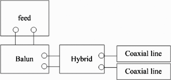
According to the simulated size of this feed, we manufactured and tested the Eleven feed. Figure 4 gives the photo of the manufactured feed. The main material of this feed is copper and the surface is silver plate. Figure 5 shows the impedance matching part of the feed. Figure 6 shows the block of the feed network. By carefully choosing the feed points and optimising the impedance transformer, we measured the feed and the VSWR was measured using an Agilent E8363B PNA network analyser. The simulated and measured results are shown in Figure 7, for discrepancy, we think there are some reasons, one is the mechanical art, the manufacture and test error interfere the discrepancy of the measured and simulated VSWR. The other is the different settings between the simulated and measured models. We choose sweep type ‘fast’, ‘lump port’ as an ideal feeding in the simulated model and drew this result. In addition, much debugging work on the folded dipoles and balun were done on the measured model. The impedance is 50 Ω in different frequencies. But for the measured model, the actual balun and hybrid are added in the ends of the shortest dipole, these did affect the whole system. This means in different frequencies, the dipoles are feeded with impedance 50 Ω, for measured model, although we have added a balun in the end of the dipoles, the impedance is not always 50 Ω in different frequencies, so there is a discrepancy between measured and simulated VSWR. The measured VSWR is almost less than 1.5 within the wide bandwidth, corresponding to the return loss better than 13.9 dB, compared to Yang et al. (Reference Yang, Chen, Wadefalk and Kildal2009), with improvement 5.9 dB in the whole frequency band.

Figure 4. The manufactured CSRH feed.

Figure 5. Impedance matching part of CSRH feed.

Figure 6. The block of feed network.

Figure 7. The measured and simulated VSWR of CSRH feed.
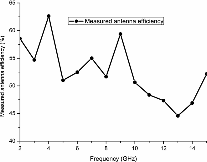
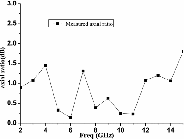
Next, we put this feed in the focus of a 2 m reflector antenna. The radiation patterns of the whole antenna system are measured by using the far-filed pattern system. The distance between the source and the feed under test is about 15 m. A frequency interval of 1 GHz is used and the angle range is limited from − 90° to +90°. The radiation patterns of CSRH antenna system are presented in Figure 8 for 4, 7, 11, and 15 GHz. It can be seen that the higher the frequency, the smaller the beam width. The first sidelobe is less than − 20 dB. Figure 9 shows the measured aperture efficiency of CSRH antenna. The antenna efficiency is above 45%. Figure 10 shows the measured axial ratio of the feed is less than 1.5dB.

Figure 8. The measured radiation patterns of CSRH antenna system.

Figure 9. The measured aperture efficiency of CSRH antenna.

Figure 10. The measured axial ratio of CSRH feed.
3 POLARISATION DEGREE MEASUREMENT
Polarisation degree measurement is also performed in this project, because polarisation degree of the radio source can provide a lot of insights into the magnetic field morphology in solar radio bursts (Yan et al. Reference Yan, Zhang, Wang, Liu, Chen and Ji2008), and such observation gives clearly variation in the emission and transport mechanism and reveals differences in solar radio source properties. The polarisation measurement is based on the interferometer polarimetry. In the observation stage, dual circularly polarisations are recorded at each antenna.
The former measurements are made by detecting two orthogonal polarisation states in a pair of antennas. In order to calibrate the observed result, all the detected correlations must be added in the instrument because of geometric path and the interference through the atmosphere. The difference caused by the outer space is modified by a front arrival time of a coming wave, so the difference in different frequency channels would cause the delay of the radio signal. In order to fully sample the polarisation states of the Sun, the phase and amplitude offsets in each channel are recorded by the signals propagating through the atmosphere, feeds, and receiving devices. Because for signal transportation, the original polarisation degree of the Sun is usually affected by the instrument. If we want to get a much more precise solar radio image, the polarisation of the instrument should be measured. As radio telescopes are sensitive to the electric field, the impact on the polarisation degree of CSRH-II could be measured by the gain difference and the isolation between right- and left-handed polarisation outputs of the polarised switch. CSRH-II receives different polarised signals when changing with the switch and correlations between parallel circular feed are sensitive to total intensity and the polarisation of the circular source, which is quite weak. When using this weak polarised source, the calibration of the instrument can be assumed to have no circular polarisation.
In our case, if we assume the original polarisation degree of the solar radio emission is Pold sun and the intensity coming to the R-polarisation channel is P right, the intensity coming to the L-polarisation channel is L pol × P right. Here,
Although the major polarisation component is assumed to be component coming from the right-handed circular channel, it is also assumed that I so works in both directions (R channel to L channel and L channel to R channel), E R and E L are the electric filed from right and left channels. AR represents the axial ratio of the feed.
The ratio of the gain coming from right channel with respect to the left channel is G = 1 + ΔG. As a result, the total right-handed polarisation power P to(right) is
The total left-handed polarisation powerP to(left) is
So, the observed polarisation degree Pold (obs) is
In Equation (5), the gain difference (ΔG) between the two channels is measured by the spectrum analyser. From these equations, we could get the error between the polarisation degree of observing the Sun and the polarisation degree of the original solar radio emission. In CSRH-II, the solar RF are mixed with three frequencies corresponding to three local oscillators, thus the intermediate frequency is 50–450 MHz.
In Figure 11, it shows the gain ratio of different powers coming from right and left circular channels in the listed frequencies, the gain difference is less than 0.2. Figure 12 shows the difference between the observing polarisation degree Pold (obs) and the original polarisation degree Pold (sun) varies with the original polarisation degree, the true value of |Pold (obs) − Pold (sun)| is less than 9.4%.

Figure 11. The gain ratio of different powers coming from right and left circular channels.

Figure 12. The relationship between |Pold (obs) − Pold (sun)| and Pold (sun).
For every receiving band, the gain difference of right- and left-handed polarisation intensities for solar emission (assuming that the solar quiet emission has no polarisation) is measured and in the future stages, the amplitude of the radio signals will be calculated according to measured data.
4 CONCLUSION
In this paper, we document the characteristics of the CSRH feed and reflector antenna and conclude that the CSRH dish perform well to meet science goals of CSRH, and this prime focus reflector dish shows good sidelobe performance for interfering sources far from the main pointing direction. This feed with bent impedance transformer with a simpler profile makes it easier to design and manufacture. The proposed feed exhibits good radiation patterns, the main measured specification VSWR is less than 1.5 over the whole frequency band, which is suitable for solar radio burst observations. At the same time, this paper also gives a method for measuring the polarisation degree by using CSRH-II data. It also gives the measured relationship between |Pold (obs) − Pold (sun)| and Pold (sun) of HC3 antenna. The difference between the measured and the original polarisation degree gives us a reference for analysing the solar radio image.
ACKNOWLEDGEMENTS
The authors would like to thank J.-C.Geng, C.-F Niu and G.-D. Yang for their assistance in 54th Research Institute.


