I. INTRODUCTION
The increasing global energy demand and accompanying climate changes as well as environmental issues are driving scientists to search for sustainable and environmentally friendly alternative sources of energy to replace exhaustible fossil fuels. Reference Shi and Zhang1 Hydrogen has been considered as an efficient and clean energy resource to replace the depleting fossil fuel in the 21st century. Reference Balogun, Qiu, Huang, Yang, Xu, Zhao, Li, Ji and Tong2,Reference Bloor, Molina, Symes and Cronin3 Recently, the electrocatalytic water splitting for generating hydrogen and oxygen has attracted extensive attentions because this process provides a promising approach for the production of a sustainable, secure, and clean hydrogen-fuel energy. Reference Kärkäs, Verho, Johnston and Åkermark4–Reference Balogun, Qiu, Yang, Fan, Huang, Fang, Li, Ji and Tong6 This electricity-driven process can be divided into two half-reactions, namely, the four-electron oxygen evolution reaction (OER) and the two-electron hydrogen evolution reaction (HER). Reference Chang, Xiao, Xiao, Ge, Liu and Xing7,Reference Fan, Balogun, Huang and Tong8 Thereinto, the OER is thermodynamically and kinetically sluggish due to the four proton-coupled electron transfer process. Reference Li, Baydoun, Verani and Brock9 Thus, it still remains a great challenge to develop the efficient and high-active bifunctional electrocatalysts for overall water splitting. Currently, the state-of-the-art electrocatalysts are the precious metal and their composites such as Pt, RuO2, and IrO2. Reference Duan, Li, Tang, He, Ji, Wang, Lv, Lopes, Paulikas, Li, Mao, Wang, Markovic, Li, Stamenkovic and Li10,Reference Lee, Suntivich, May, Perry and Shao-Horn11 However, the high cost and limited availability of noble metals potentially obstruct their large-scale applications in overall water splitting. In this case, tremendous research efforts have been focused on the low-cost and earth-abundant catalysts as alternatives to the noble metal. For example, Yang’s group reported the iron-nickel sulfide (INS) ultrathin nanosheets (NSs) that enabled a catalytic current density of 10 mA/cm2, an even lower overpotential of 105 mV at 10 mA/cm2, and a smaller Tafel slope of 40 mV/dec for HER. Reference Long, Li, Wang, Zhu, Zhang, Xiao, Guo and Yang12 Also, Sun’s group synthesized new hierarchically multifunctional porous nickel sulfide superstructures (h-NiS x ) through electrodeposition of porous metallic Ni microsphere arrays on a nickel foam followed by low-temperature sulfurization. Reference You and Sun13 The h-NiS x exhibited outstanding catalytic performance for both HER and OER in an alkaline electrolyte (1.0 M KOH), in which the overpotentials of h-NiS x to afford a current density of 10 mA/cm2 are as small as 60 mV for HER and 180 mV for OER in 1.0 M KOH, respectively. Reference You and Sun13 Except for the transition metal sulfides, Reference Long, Li, Wang, Zhu, Zhang, Xiao, Guo and Yang12,Reference You and Sun13 transition metal selenides, Reference Xu, Ding, Jia, Lu, Chen, Zhou, Cheng, Liu, Wu and Xie14,Reference Wang, Li, Shifa, Liu, Wang, Wang, Xu, Wang and He15 carbides, Reference Xu, Ding, Lv, Chen, Lu, Cheng, Zhou, Liu, Wu, Wu and Xie16,Reference Wan and Leonard17 borides, Reference Chen, Xu, Zhou, Tong, Wu, Cheng, Lu, Ding, Wu and Xie18 nitrides, Reference Liu, Zhang, Yan, Yan, Liu, Yang, Miao, Wang, Wang and Zhang19,Reference Hu, Yang, Wang, Zhang, Lu and Wang20 and phosphides Reference Li, Gao, Wang, Xiong, Huang, Song, Bao and Liu21–Reference Zhang, Hao, Yang and Tang26 have also been extensively studied in recent years. A series of magnetic iron-doped molybdenum carbide (Mo2−x Fe x C) nanomaterials were synthesized by Wan et al. for the first time and enhanced catalytic activities for HER were obtained. Reference Wan and Leonard17 Also, Hu et al. fabricated Co–N–mC catalysts in which two forms of metals including coordinating Co moieties and Co nanoparticles (CoNPs) were encapsulated in mesoporous N-doped carbon hollow spheres (Co–N–mC). Reference Hu, Yang, Wang, Zhang, Lu and Wang20 The obtained Co–N–mC showed excellent catalytic performance for the oxygen reduction reaction.
Among them, transition metal phosphides such as Ni–P, Reference Li, Gao, Wang, Xiong, Huang, Song, Bao and Liu21–Reference Wang, Kolen’ko and Liu23 Co–P, Reference Saadi, Carim, Verlage, Hemminger, Lewis and Soriaga24–Reference Zhang, Hao, Yang and Tang26 Fe–P, Reference Jiang, Liu, Liang, Tian, Asiri and Sun27 Mo–P, Reference Kibsgaard and Jaramillo28 and W–P, Reference McEnaney, Crompton, Callejas, Popczun, Read, Lewis and Schaak29 have drawn intense attention because of their good electrocatalytic performance for overall water splitting. Especially, nickel phosphide is considered as the most promising prospect due to the excellent electrocatalytic performance toward HER and OER. Reference Li, Gao, Wang, Xiong, Huang, Song, Bao and Liu21–Reference Wang, Kolen’ko and Liu23 To achieve high catalytic activity, numerous nickel phosphide nanomaterials with various micro/nanostructures like nanowires, NSs, nanoparticles, and nanonflowers were prepared by different methods such as high-temperature wet chemical processes, Reference Popczun, McKone, Read, Biacchi, Wiltrout, Lewis and Schaak30 hydrothermal methods, Reference You, Jiang, Sheng, Bhushan and Sun31 electrochemical deposition, Reference Liu, Gu and Li32 and phosphidation of nanostructured nickel oxide/hydroxides. Reference Wang, Li, Xiong, Petrovykh and Liu22,Reference Stern, Feng, Song and Hu33 Li et al. reported the bifunctional Ni x P y -325 catalysts that enabled a catalytic current density of 10 mA/cm2 at 1.57 V in the alkaline media for overall water splitting. Reference Wang, Kolen’ko, Bao, Kovnir and Liu34 Afterward, Stern et al. synthesized Janus Ni2P catalysts that achieved a current density of 10 mA/cm2 toward overall water splitting at 1.63 V in the alkaline electrolyte. Liu et al. synthesized the Ni–P nanoparticles that can achieve a current density of 10 mA/cm2 at 1.68 V in the alkaline media for overall water splitting. Reference Stern, Feng, Song and Hu33 Recently, the direct phosphorization of nickel foam to fabricate 3D nickel phosphide nanostructures has been found to perform high electrocatalytic activities for hydrogen production. Reference Wang, Kolen’ko and Liu23,Reference Xiao, Lv, Zhang, Zhang and Wang35 For example, Wang et al. reported a one-step route to the synthesis of an integrated nickel phosphide nanorods/nickel (Ni2P-NRs/Ni) electrode by direct phosphorization of commercially available Ni foam under solvothermal conditions using red phosphorus as the precursor, showing better electrochemical performance for HER. Reference Wang, Kolen’ko and Liu23 Also, Liu’s group reported a very simple and straight forward method to fabricate self-supported biphasic Ni5P4–Ni2P NS arrays for HER by direct phosphorization of the Ni foam using phosphorus vapor without complicated chemical reactions and post treatment steps involved. Reference Xiao, Lv, Zhang, Zhang and Wang35 Additionally, three-dimensional (3D) porous Ni/Ni8P3 electrodes and Ni12P5/Ni2P nanowires were prepared by phosphorization of commercial Ni foam, respectively, for the overall water splitting. Reference Chen, Ma, Liu, Li, Su, Davey and Qiao36,Reference Li, Li, Zhou, Gao, Ma and Qu37 Despite this significant progress, they still suffered from the large overpotential for oxygen production, which lead to the high cell voltage of water electrolysis. Therefore, the development of alternative bifunctional electrocatalysts with low overpotential and long-term stability is highly desirable and challenging.
To obtain the optimal catalyst for overall water splitting, a variety of reaction conditions have been changed in the synthesis of transition metal phosphide, such as changing the reaction time and temperature or changing the quantity of phosphorus source. Reference Wang, Li, Xiong, Petrovykh and Liu22,Reference Yang, Lu, Zhu, Hedhili, Min, Huang, Han and Li25,Reference You, Jiang, Sheng, Gul, Yano and Sun38 For example, You et al. synthesized a series of Co–P/NC under different phosphidation times and achieved the best HER and OER activity at 2 h. Reference You, Jiang, Sheng, Gul, Yano and Sun38 Although there have been many reports focused on the method of direct phosphorization of the nickel foam to synthesis nickel phosphide, only few have studied the effect of phosphating time on the performance of HER and OER when NaH2PO2 is used as the phosphorus source. Therefore, we tested the effects of phosphating time on their electrocatalytic activities toward HER and OER in the alkaline media.
Herein, we synthesized the biphasic Ni12P5–Ni2P nanorod arrays by direct phosphorization of commercial nickel foam (Ni foam) with different phosphating times. The method requires neither a special nickel precursor nor a surface-active agent added but to achieve well-dispersed Ni–P nanorod arrays that are directly grown on the Ni foam surface. The effects of phosphating time on their electrocatalytic activities toward HER and OER were investigated in the alkaline media. The results show that the phosphating time plays a crucial role to the electrocatalytic activities for OER and HER. The as-prepared Ni–P nanorods with two hours of phosphating treatment display an overpotential of 270 mV to generate a current density of 30 mA/cm2 for OER and an overpotential of 158 mV to deliver a current density of 10 mA/cm2 for HER as well as excellent stability in 1.0 M KOH, which demonstrate that the as-prepared self-supported Ni–P nanorod array electrode can be directly used either as a cathode to drive HER or as an anode to expedite OER without any post treatment. As a result, a cell voltage as low as 1.6 V is needed to drive a current density of 10 mA/cm2 for overall water splitting, when the Ni–P nanorods are used as a bifunctional electrode for basic water splitting. Moreover, Ni–P nanorods possess high efficiency and long-term stability, indicating a low-cost and high-performance electrocatalyst for full water splitting.
II. EXPERIMENTAL SECTIONS
A. Materials
Nickel foam with a thickness of 1.6 mm and a pore density of 110 ppi was purchased from Changsha Keliyuan Instruments Co., Ltd. (Changsha, China). Sodium hypophosphite (NaH2PO2·H2O), HCl (37.5%) and acetone (99.5%) were all of analytical grade and used as purchased without further purification. Iridium(IV) dioxide (IrO2) was purchased from Alfa Aesar (Haverhill, Massachusetts). Carbon-supported Pt nanoparticles (Pt/C, 20 wt% Pt) were supplied by Johnson Matthey Inc. (New York, New York). Nafion (5% in a mixture of lower aliphatic alcohols and water) was purchased from Sigma-Aldrich (St. Louis, Missouri). Ultrapure water (18.2 MΩ/cm) supplied with an Aike water system was used for solution preparation.
B. Preparation of Ni–P nanorod arrays on Ni foam
Caution: Because this procedure involves the high-temperature decomposition of sodium hypophosphite that can liberate phosphine, this reaction should be considered as highly corrosive and flammable and therefore should only be carried out by a person who is trained appropriately under rigorous air-free conditions.
Ni–P nanorod arrays were prepared according to the reference with minimal changes. Reference Li and Zhao39 Firstly, the Ni foam (1 × 2 cm) was completely immersed in an ultrasound bath of acetone, 3 M HCl, ethanol, and DI water, respectively, for 15 min to well clean the surface of the Ni foam and then dried at room temperature. Secondly, the treated Ni foam was loaded on the top of the ceramic boat with 0.3 g NaH2PO2·H2O powder at the bottom. And then the furnace was heated up to 300 °C with a heating rate of 1 °C/min under a flow of N2 atmosphere and kept at 300 °C for different times, such as 1, 2, and 3 h. After cooling down to room temperature, the samples were taken out and rinsed several times with DI water and ethanol, respectively, and then dried under vacuum at 60 °C. The Ni–P nanorod samples prepared with different phosphating times were denoted as Ni–P 1 h, Ni–P 2 h, and Ni–P 3 h, respectively.
C. Material characterizations
Powder X-ray diffraction (XRD) patterns were obtained by a Rigaku D/Max-2400 diffractometer with Cu Kα irradiation (λ = 1.5406 Å) at a scanning rate of 5°/min from 10 to 80° to characterize the crystal structure of the samples. The morphology and microstructure of the samples were investigated by field emission scanning electron microscopy (FESEM; JEOLJSM-S4800, JEOL Ltd., Tokyo, Japan; operating voltage, 5 kV) and transmission electron microscopy (TEM; TecnaiTM G2F30, FEI, Hillsboro, Oregon; operated at 200 kV) with energy dispersive spectroscopy EDX and selected area electron diffraction SAED. X-ray photoelectron spectroscopy (XPS) measurements were recorded by using a VGESCALBMKII X-ray photoelectron spectrometer (VG Instruments, Middlewich, United Kingdom) with monochromated Al Kα radiation (1486.6 eV).
D. Electrochemical measurements
The HER and OER properties were recorded at room temperature on a CHI 760E electrochemical workstation with a three-electrode system, equipped with a Hg/HgO reference electrode and a Pt plate (2 × 2 cm) counter electrode. The as-prepared Ni–P nanorod arrays on the Ni foam were directly used as the working electrode. Cyclic voltammetry was carried out at a scan rate of 5 mV/s to activate the as-fabricated electrodes. The polarization curves for HER and OER were recorded by a linear sweep of potential from −0.8 to −1.5 and 0 V–0.8 V (versus Hg/HgO) with a sweep rate of 5 mV/s, respectively. Electrochemical impedance spectroscopy (EIS) was tested in the frequency range from 105 to 10−2 Hz at open circuit potential at room temperature. For overall water splitting tests, the obtained Ni–P nanorod electrodes were used as negative and positive electrodes for HER and OER, respectively. The CV curve was obtained from 0 to 2 V at a scan rate of 5 mV/s. All the polarization curves were recorded with 95% iR compensation. IrO2 and 20 wt% Pt/C was loaded on the nickel foam with 2.5 mg/cm2 for the comparative experiments. The working electrodes of IrO2 and 20 wt% Pt/C were prepared as follows: a homogeneous suspension was firstly prepared by ultrasonically mixing 2.5 mg of IrO2 or 20 wt% Pt/C with 50 μL of Na+-exchanged Nafion solution and 950 μL of isopropanol solvent for 30 min. Then, 1 mL of the prepared catalytic suspension was loaded onto the surface of an Ni foam (1 × 1 cm) using a micropipette. Finally, the electrode was allowed to dry overnight under atmosphere at room temperature to form a thin catalyst film on the Ni foam. The electrolyte in all the experiments was 1.0 M KOH aqueous solution.
III. RESULTS AND DISCUSSION
A. Composition, structure and morphology
Sodium hypophosphite (NaH2PO2) has been proven to be an effective phosphorus source to prepare specific phosphides. Reference Wang, Li, Xiong, Petrovykh and Liu22,Reference Wang, Kolen’ko and Liu23,Reference Wang, Kolen’ko, Bao, Kovnir and Liu34,Reference Ledendecker, Krick Calderón, Papp, Steinrîck, Antonietti and Shalom40 The biphasic Ni–P nanorods were grown on the acid-treated Ni Foam via direct phosphorization of the Ni foam in a tube furnace, where NaH2PO2·H2O provided the phosphorous vapor. In this process, the Ni foam turned black but maintains its three-dimensional structure. Thus, it can be directly used as an electrode for HER and OER without any post processing steps. Furthermore, the Ni–P electrode showed high flexibility, which was beneficial for being used as a water splitting electrode. To inspect the surface morphologies of the self-supported Ni–P electrodes, FESEM was first carried out, and the FESEM images of the samples with different phosphorization times are shown in Fig. 1. Figure 1(a) shows the smooth surface of the acid-treated Ni foam with some visible pores. As shown in Figs. 1(b)–1(d), numerous nanorods with diameters of ∼500 nm were lushly grown on the surface of the Ni foam after direct phophorization of the Ni foam, and the nanorods displayed a rough surface composed of the tiny fibers, which can provide high specific surface area for the outstanding electrochemical properties. From Figs. 1(b)–1(d), it can be also concluded that the phosphorization time had an unconspicuous influence on the surface morphologies of the samples.

FIG. 1. FESEM of (a) Ni foam and the Ni–P samples with different phosphating treatments for (b) 1 h, (c) 2 h, and (d) 3 h.
The XRD was then executed to detect the crystal texture of the obtained Ni–P electrode at different phosphorization times. As shown in Fig. 2(A), hexagonal Ni12P5 (JCPDS No. 74-1381) Reference Duan and Wang41 and Ni2P (JCPDS No. 74-1385) Reference Tian, Li, Wang, Prins, Chen and Hu42 can be clearly found from the Ni–P samples obtained by direct phosphotization of the Ni foam, except for the metallic Ni phase. The diffraction peaks located at 40.7°, 44.8°, 47.4°, 54.2°, and 74.8° can be indexed to the (111), (201), (210), (300), and (212) planes of the cubic phase Ni2P (JCPDS No. 74-1385), Reference Tian, Li, Wang, Prins, Chen and Hu42 while the peaks at 38.4°, 41.7°, 47.4°, and 48.9° correspond to the (112), (400), (201), and (312) planes of Ni12P5 (JCPDS No. 74-1381). Reference Duan and Wang41 In addition, the strong peaks at 44.5°, 52.0°, and 76.5° can be assigned to the metal Ni, which is from the Ni substrate. Moreover, the phosphorization time has an unconspicuous influence on the dominate phase of the samples. The mass loading of Ni–P samples with a phosphating treatment of two hours is averaged and calculated to be in the range of 2.37 (Ni2P)–2.74 (Ni12P5) mg/cm2, according to the molar of P and the results of XRD.
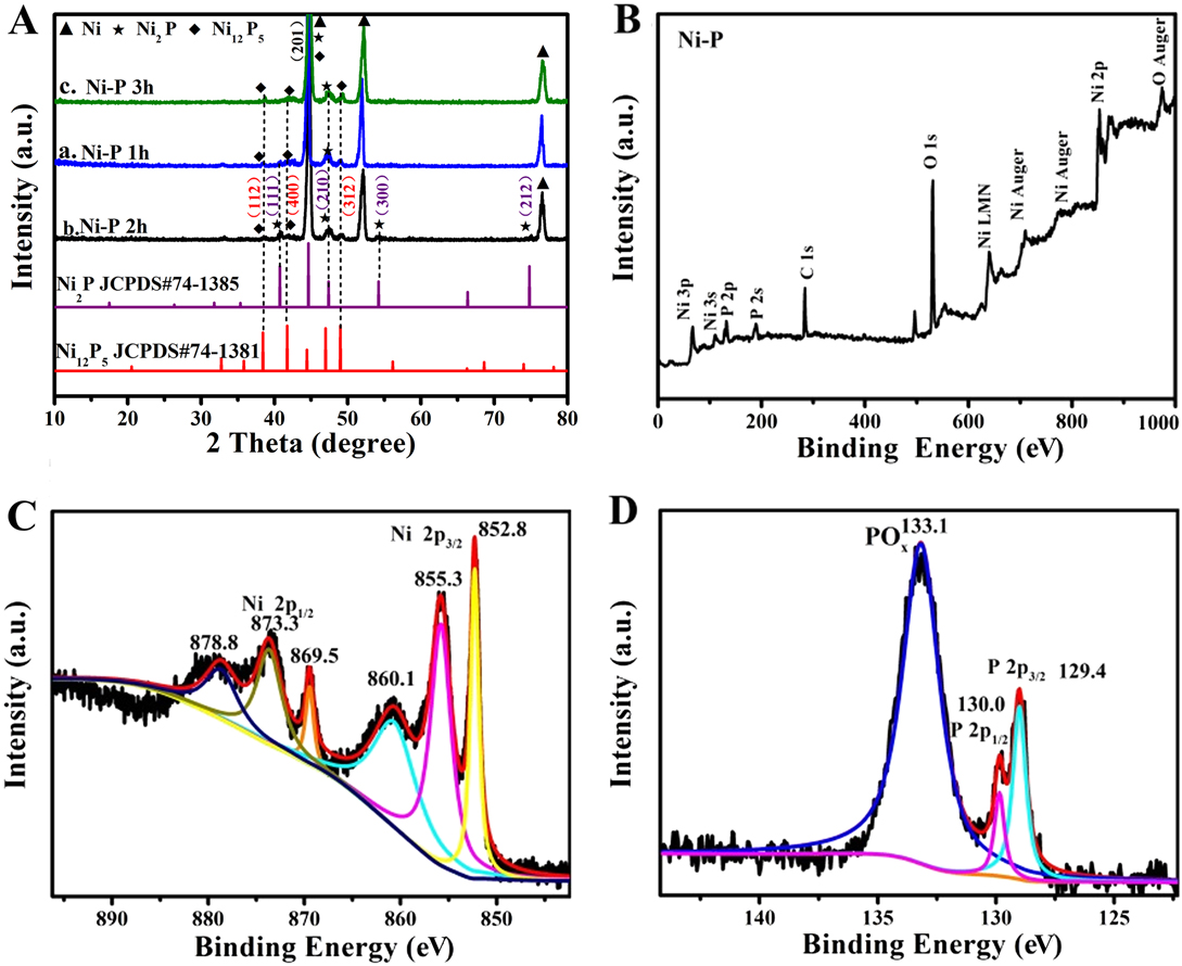
FIG. 2. (A) XRD patterns of the Ni–P samples with phosphating treatment for (a) 1 h, (b) 2 h, and (c) 3 h. (B) XPS survey spectrum and high-resolution spectra of Ni 2p (C) and P 2p (D) for the Ni–P sample with 2 h phosphating treatment.
Moreover, the surface chemistry states of the Ni–P sample with a phosphating treatment of two hours were investigated by XPS due to the preferable electrochemical performance. The XPS survey spectra clearly proved the presence of Ni and P in the Ni–P sample [Fig. 2(B)]. Reference Liu, Gu and Li32 The high-resolution spectrum of Ni 2p [Fig. 2(C)] clearly shows two spin–orbit doublets of Ni 2p 3/2 and Ni 2p 1/2 and two shake-up satellites (identified as “sat.”) at 860.1 eV and 878.8 eV, respectively. Reference Liu, Gu and Li32,Reference Sun, Zheng, Li and Du43 The peaks [Fig. 2(C)] at 852.8 and 869.5 eV can be assigned to the metal Ni which originated from the Ni substrate, and the peaks at 855.3 and 873.7 eV are corresponding to the oxidized Ni species in the Ni–P sample. Reference Liu, Gu and Li32,Reference Xiao, Lv, Zhang, Zhang and Wang35 Figure 2(D) shows the XPS spectrum of P 2p, which can also be split into two peaks at binding energies of 129.4 and 130.0 eV, corresponding to P 2p 3/2 and P 2p 1/2, and the other peak centered at 133.1 eV, which is assigned to the oxidized phosphorus species, such as PO4 3− or P2O5, Reference Wang, Li, Xiong, Petrovykh and Liu22,Reference Liu, Gu and Li32,Reference Stern, Feng, Song and Hu33 arises from the inescapable contact between the Ni–P surface and air. These results confirm the direct formation of nickel phosphate on the Ni foam without using extra nickel precursors. Reference Wang, Li, Xiong, Petrovykh and Liu22,Reference Liu, Gu and Li32,Reference Stern, Feng, Song and Hu33
To further study the microstructure and chemical composition of the nanorods, TEM of the Ni–P sample with a phosphating treatment for two hours was also carried out and shown in Fig. 3. The Ni–P nanorod shows a cone-like morphology with a length of about 4 μm and a diameter of about 500 nm [Fig. 3(a)]. The HRTEM exhibits well-defined lattice fringes of an adjacent space of 0.218 nm, confirming the (111) plane of the hexagonal Ni2P, Reference Sun, Zheng, Li and Du43,Reference Zhou, Zhou, Yang, Lu, Cheng, Mai, Tang, Li and Chen44 as shown in Fig. 3(b). The chemical compositions of Ni–P were measured by elemental mapping, verifying the homogeneous distribution of Ni and P elements across the nanorod structure [Figs. 3(c)–3(e)]. All of the results clearly confirm the successful growth of nickel phosphide nanorod arrays on the Ni foam after direct phosphorization treatment of the Ni foam.
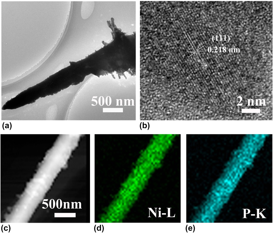
FIG. 3. TEM (a), HRTEM (b), STEM (c), and the elemental mapping (d, e) images of the Ni–P sample with 2 h of phosphating treatment.
B. Electrocatalytic properties toward HER and OER
Electrocatalytic properties of the Ni–P nanorods were evaluated using a typical three-electrode setup. Firstly, we investigated the effect of reaction time on the electrocatalytic activity for HER and OER in 1 M KOH solution, respectively, as shown in Figs. 4 and 5. The linear sweep voltammograms (LSVs) of HER in Fig. 4(A) reveal that the Ni–P samples possess a much lower onset overpotential and higher current density than those of bare Ni foam. When the phosphorization time is two hours, the electrocatalytic activity of the Ni–P sample for HER attains the highest level. It only needs an overpotential of 158 mV to drive the current densities of 10 mA/cm2, which is comparable to those of many reported Ni-phosphide-based electrocatalysts in the alkaline media (see Table I). Increasing or decreasing the reaction time would induce a decreased activity for Ni–P, suggesting a phosphating time-depended HER catalytic activity for the Ni–P catalysts. Figure 4(B) presents the Tafel plots of the Ni foam, Pt/C, and the Ni–P samples with different phosphating times. These Tafel plots are fitted to the Tafel equation (η = b log [j] + a, where j is the current density and b is the Tafel slope). Reference Wang, Kolen’ko and Liu23,Reference Xiao, Chen and Wang45 The Tafel slope of 38 mV/dec for Pt/C is consistent with the value reported in the literature. Reference Popczun, McKone, Read, Biacchi, Wiltrout, Lewis and Schaak30,Reference Feng, Vrubel, Bensimon and Hu46 The Ni–P exhibits a Tafel slope of 75 mV/dec, which is larger than that of Pt/C (38 mV/dec) but lower than that of the Ni foam (108 mV/dec) and superior to that of many earth-abundant HER catalysts reported recently, such as Ni–P nanoparticles (87 mV/dec at η = 60–140 mV, 81 mV/dec at η = 150–200 mV), Reference Feng, Vrubel, Bensimon and Hu46 Ni2P (87 mV/dec) Reference Popczun, McKone, Read, Biacchi, Wiltrout, Lewis and Schaak30 and different Mo2C nanocrystals (110–235 mV/dec). Reference Alhajri, Anjum and Takanabe47 Benefiting from the lower Tafel slope, the smaller overpotential is required to achieve the same cathodic current density, suggesting a faster HER response for Ni–P electrode. Additionally, according to the previous report, Reference Li, Li, Zhou, Gao, Ma and Qu37,Reference Yu, Li, Chen, Xu, Zhen, Wu and Dravid48 the Tafel slope of 75 mV/dec shows a combined Volmer (H2O + e− → Hads + OH−)–Heyrovsky (Hads + H2O + e− → H2 + OH−) mechanism for HER in the alkaline media. Such a pathway includes the adsorption of H2O and the electrochemical decomposition of trapped H2O into the adsorbed H atoms (Hads) and OH− species and then the detachment of OH− to refresh the surface and the formation of Hads to yield H2.
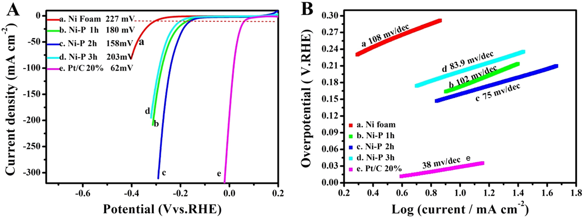
FIG. 4. The LSVs (A) and the corresponding Tafel plots (B) of Ni foam (a), Pt/C (e) and the Ni–P samples with phosphating treatment for (b) 1 h, (c) 2 h, and (d) 3 h for HER.
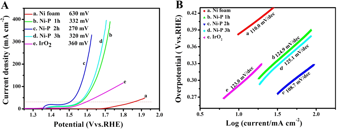
FIG. 5. The LSVs (A) and the corresponding Tafel plots (B) of Ni foam (a), IrO2 (e) and the Ni–P samples with phosphating treatment for (b) 1 h, (c) 2 h, and (d) 3 h for OER.
TABLE I. Overpotential and Tafel slope of the reported Ni-phosphide-based electrocatalysts for OER and HER in 1 M KOH.
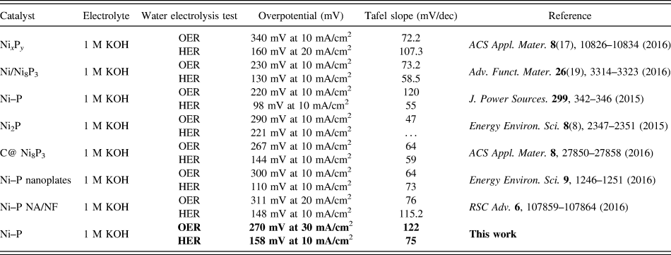
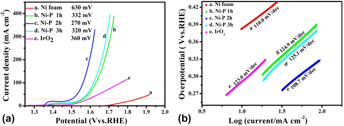
Compared to HER, OER, the anodic reaction of water splitting, is usually more difficult to accomplish, as it is a thermodynamically and kinetically demanding process involving four sequential proton-coupled charge transfer steps and the O=O bond formation. The Ni–P samples also show superior electrochemical activity toward OER. Figure 5 is the LSVs and the corresponding Tafel plots for OER. Note that the polarization curves of Ni–P samples have an obviously oxidative peak at 1.4 V versus RHE, which is ascribed to the oxidation of Ni species. Reference Stern, Feng, Song and Hu33 After that, it begins for OER. Reference Stern, Feng, Song and Hu33 The current density of oxidative peaks is about 20 mA/cm2. Therefore, to eliminate the effect of the anodic peak current of Ni species, the overpotential at a current density of 30 mA/cm2 is used to certify the electrochemical activity of Ni–P samples. At the current density of 30 mA/cm2, the Ni–P sample with phosphating treatment for two hours shows the smallest overpotential of 270 mV, compared to other samples including the Ni foam, the commercial benchmark OER catalyst IrO2. Additionally, it is superior to or comparable with the behavior of other Ni-phosphide-based electrocatalysts (as show in Table I) and other transition metal phosphide in the alkaline media, such as Ni x P y (340 mV for 10 mA/cm2), Reference Li, Li, Zhou, Gao, Ma and Qu37 Ni2P (290 mV for 10 mA/cm2), Reference Stern, Feng, Song and Hu33 Co–P (319 mV for 10 mA/cm2), Reference You, Jiang, Sheng, Gul, Yano and Sun38 CoMnP (330 mV for 10 mA/cm2), Reference Li, Baydoun, Verani and Brock9 CoP (320 mV for 10 mA/cm2), Reference Chang, Xiao, Xiao, Ge, Liu and Xing7 CoP hollow polyhedron (400 mV for 10 mA/cm2), Reference Liu and Li49 Ni–P/C (300 mV for 10 mA/cm2), Reference Yu, Li, Chen, Xu, Zhen, Wu and Dravid48 and other non-precious metal-based electrocatalysts, such as amorphous NiO (470 mV for 10 mA/cm2), Reference Dong, Sun, Dai, Zang and Dong50 NiCo2O4 (391 mV for 10 mA/cm2), Reference Peng, Jia, Al-Enizi, Elzatahry and Zheng51 Ni/Ni3N foam (399 mV for 10 mA/cm2), Reference Shalom, Ressnig, Yang, Clavel, Fellinger and Antonietti52 NiCo LDH (393 mV for 10 mA/cm2), Reference Liang, Meng, Cabán-Acevedo, Li, Forticaux, Xiu, Wang and Jin53 and Ni–Co–O@NiCo–S NA (286 mV for 10 mA/cm2) Reference Xu, Lu, Lei, Li and Sun54 and is even comparable with the behavior of IrO2 (340 mV) Reference Luo, Im and Mayer55 in 1.0 M KOH. The OER kinetics of the Ni–P electrode is also estimated by corresponding Tafel plots [Fig. 5(B)]. A high-performance electrocatalyst with lower overpotential requires less energy to achieve the same current density. Compared to the HER, the OER is usually more difficult to accomplish, as it is a thermodynamically and kinetically demanding process involving four sequential proton-coupled charge transfer steps and the O=O bond formation. The advantage of the Ni–P electrode on OER is significant for an electrode when used as water splitting. The OER kinetics is also estimated by corresponding Tafel plots [Fig. 5(B)] for these electrodes. The Tafel slope for Ni–P is 106 mV/dec, which is smaller than that of the Ni Foam (110 mV/dec), IrO2 (123 mV/dec), Ni–P 1 h (124.9 mV/dec), and Ni–P 3 h (125.1 mV/dec), implying a more rapid OER rate for the Ni–P electrode.
To investigate the internal character of all the electrode materials, the exchange current density (j 0) was calculated using extrapolation methods. Reference Xiao, Chen and Wang45,Reference Liu, Tian, Cui, Jiang, Cheng, Asiri and Sun56 Exchange current density is the intrinsic property of the electrode reaction, which depends only on catalyst materials, electrolyte, and temperature. Reference Shi and Zhang1 It reflects the ability of electron transfer and the difficulty of an electrode reaction. The internal reason of overpotential is the exchange current density. Reference Xiao, Chen and Wang45,Reference Liu, Tian, Cui, Jiang, Cheng, Asiri and Sun56 Electrode reactions with a larger exchange current density need less driving force (smaller current density) to conduct the reaction. The intersection of the extrapolated linear part of the Tafel plots and the X-axis is the exchange current density. Reference Shi and Zhang1 For HER, when the overpotential value is 0, the log[j] values for the Ni foam, Ni–P 1 h, Ni–P 2 h Ni–P 3 h, and Pt/C are −1.9, −1.1, −0.7, −1.4, and 0.33, respectively. Based on Tafel equations (η = b log[j] + a, where j is the current density and b is the Tafel slope), j 0 for the Ni foam, Ni–P 1 h, Ni–P 2 h, Ni–P 3 h, and Pt/C were calculated to be 0.013, 0.078, 0.204, 0.035, and 2.18 mA/cm2, respectively. Moreover, for OER, the log[j] values for the Ni foam, Ni–P 1 h, Ni–P 2 h Ni–P 3 h and IrO2 are −2.46, −1.18, −1.055, −1.10, and −1.36, respectively. j 0 for the Ni foam, Ni–P 1 h, Ni–P 2 h Ni–P 3 h, and Pt/C were calculated to be 0.003, 0.066, 0.088, 0.079, and 0.043 mA/cm2, respectively. For both HER and OER, the Ni–P 2 h electrode possess the maximum exchange current density compared to the Ni foam, Ni–P 1 h, and Ni–P 3 h, which proves that the Ni–P 2 h electrode is the optimal catalyst for HER and OER.
The above results demonstrate the desired electrocatalytic activity of the Ni–P nanorods prepared by two hours of phosphorization of the Ni foam, which could be caused by the difference in the number of active sites and the charge transfer capacity of the active materials. The relative electrochemical active surface (ECSA) is proportional to the number of electrochemically active sites. An efficient method to estimate the ECSA is to test the electrochemical double-layer capacitance (C dl), which is assumed to be linearly proportional to the ECSA (ECSA = C dl/C s, C s is specific capacitance). Reference Zhang, Gan, Wu, Ma, Han and Niu57,Reference Swesi, Masud and Nath58 The CV curves were swept in the potential range of 0.92–1.02 V versus RHE at various scan rates (20, 40, 60, 80, 100 mV/s) and shown in Figs. 6(A)–6(C). From Fig. 6(D), the C dl can be calculated to be 15.1 mF/cm2, 16.2 mF/cm2, and 14.9 mF/cm2 for Ni–P 1 h, Ni–P 2 h, and Ni–P 3 h, respectively. In this study, the value of C s that we use is 0.040 mF/cm2, which is based on the previously reported Ni-based OER catalysts. Reference Swesi, Masud and Nath58 The EASA of Ni–P 2 h can be calculated as 405 cm2, which is higher than that of Ni–P 1 h (ECSA = 377.5 cm2) and Ni–P 3 h (ECSA = 372.5 cm2). These results confirm that the Ni–P 2 h sample possesses the largest active surface area and enhanced active sites among the three samples. Furthermore, the EIS of the as-prepared samples was also used to evaluate the electrocatalytic kinetics during the electrochemical process. The Nyquist plots [Fig. 6(E)], which were tested at the same applied voltage, show that the Ni–P 2 h sample has the smallest charge transfer resistance compared with the Ni–P 1 h and Ni–P 3 h samples, promoting electron charge transfer and offering faster electrochemical kinetics. Reference Li, Li, Zhou, Gao, Ma and Qu37
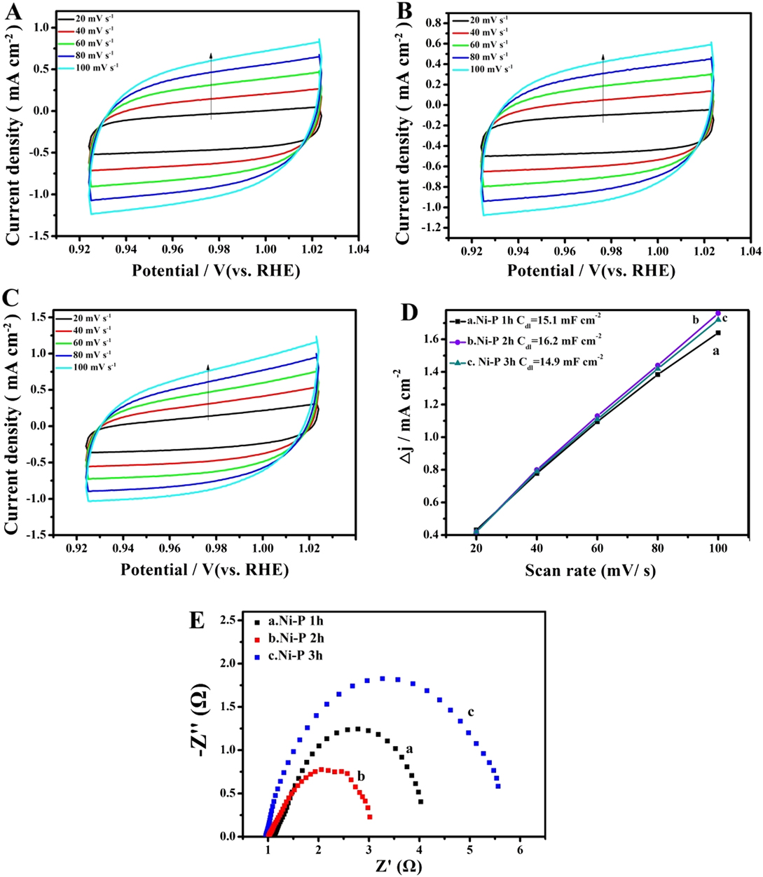
FIG. 6. CV curves between 0.92 and 1.02 V of the Ni–P samples with phosphating treatment for (A) 1 h, (B) 2 h, and (C) 3 h at different scan rates; (D) Plots of the current density versus scan rates derived from CV curves and (E) EIS of the Ni–P samples with phosphating treatment for (a) 1 h, (b) 2 h, and (c) 3 h.
Durability and stability in high concentration alkaline solutions are important parameters to evaluate the performance of catalysts in practical applications. Therefore, the electrocatalytic stability of the Ni–P sample with two hours of phosphating treatment toward HER and OER was also investigated using chronoamperometry at a constant overpentional of 158 mV for HER and 270 mV for OER in 1 M KOH, respectively. As shown in Figs. 7(a) and 7(c), a stable current density of about 10 mA/cm2 for over 24 h of continuous operation was obtained at a constant overpentional of 158 mV for HER. While the sample shows a slightly lower current density than 30 mA/cm2 at a constant overpentional of 270 mV for OER, the degradation of the current density is negligible after a long period of 24 h. The favorable stability of the Ni–P nanorods was also certified from long-term potential cycling by taking continuous CV scans at 10 mV/s for 3000 cycles. The LSVs are recorded before and after 3000 cycles are displayed in Figs. 7(b) and 7(d). Upon 3000 continuous CV cycles at 10 mV/s, the polarization curves for HER and OER show a slight decay with an overpotential increase of about 8.6 mV and 5.5 mV at 10 mA/cm2 and 30 mA/cm2, respectively, compared with the initial one. In addition, the FESEM images of the Ni–P sample after 3000 CV cycles in 1 M KOH solution for HER and OER still maintain the shape of the nanorods, and no obvious change of the surface morphology was found, indicating the outstanding structural stability of Ni–P nanorod electrodes [insert of Figs. 7(c) and 7(d)].
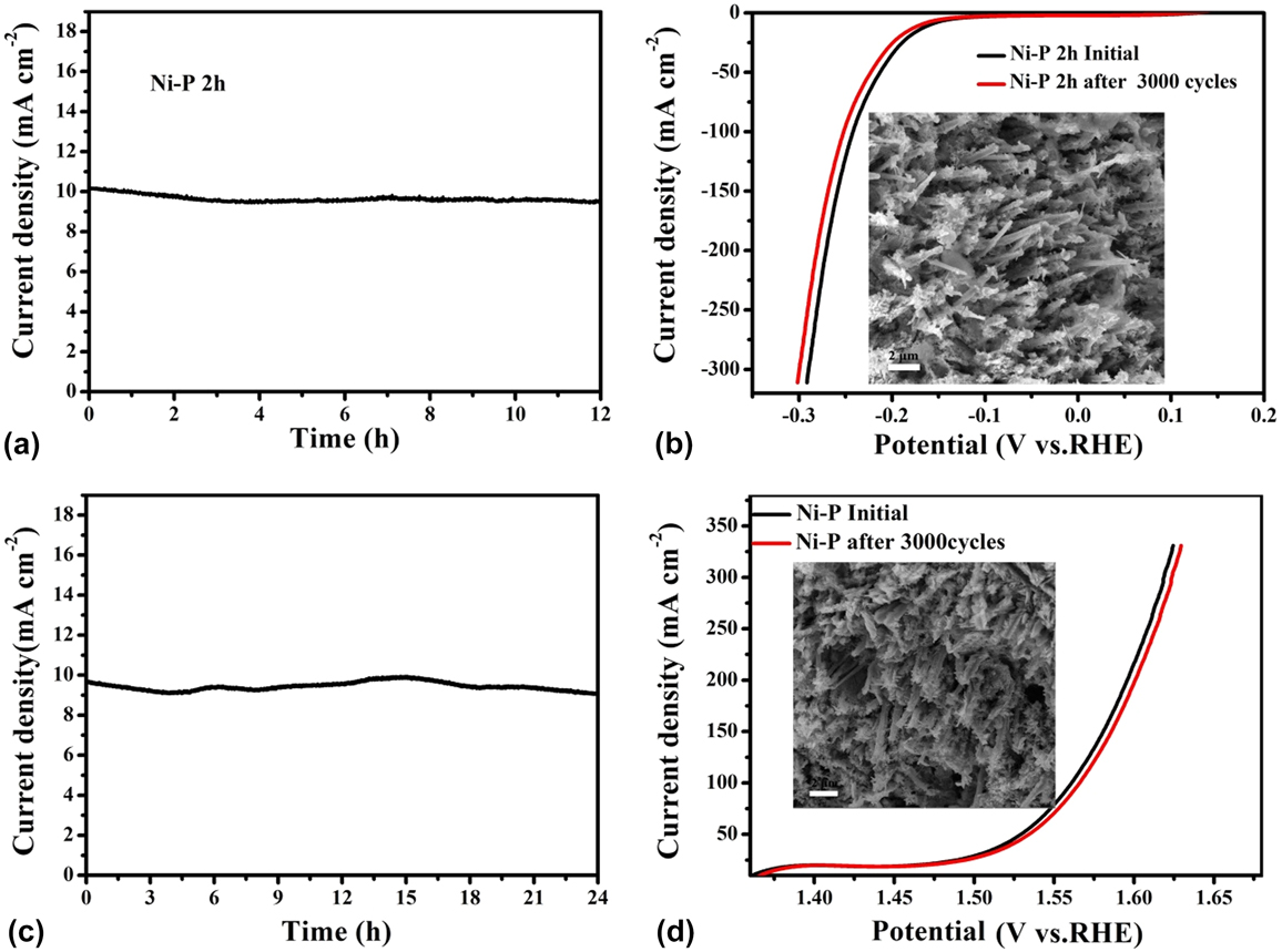
FIG. 7. Chronoamperometric measurements under static overpotential and LSVs recorded before and after 3000 cycles of CV scans for long-term stability tests of the Ni–P sample with two hours of phosphating treatment for HER (a, b) and OER (c, d). Inset: FESEM images of the Ni–P sample after 3000 cycles of CV scans for HER and OER in 1 M KOH solution.
C. The electrocatalytic performance of Ni–P nanorods for overall water splitting
Inspired by the active and stable catalytic activity of the Ni–P catalysts for two half-reactions of water electrolysis in 1.0 M KOH, we believed that it could act as an electrocatalyst for overall water splitting. To illustrate the practical application of the Ni–P sample with two hours of phosphating treatment, the overall water splitting reaction was researched based on a two-electrode setup using Ni–P as both anode and cathode toward OER and HER in a basic environment. A catalytic current was observed when the applied potential was larger than 1.50 V [Fig. 8(a)]. Under the circumstances, a low decomposition voltage of 1.6 V is needed to afford a current density of 10 mA/cm2 for overall water splitting [Fig. 8(a)]. This potential compares favorably with the reported results, such as C@Ni8P3 (1.65 V), Reference Yu, Li, Chen, Xu, Zhen, Wu and Dravid48 Ni–P (1.68 V), Reference Liu, Gu and Li32 Ni2P (1.6 V), Reference Wang, Li, Xiong and Liu59 Ni–P (1.69 V), Reference Chen, Ma, Liu, Li, Su, Davey and Qiao36 CP @ Ni–P (1.63 V) Reference Wang, Li, Xiong, Petrovykh and Liu22 Ni–P (∼1.65 V), Reference Jiang, You, Sheng and Sun60 as well as commercial electrolyzers (1.8–2.0 V), as shown in Table II. Reference Zeng and Zhang61 Additionally, the Ni–P sample with two hours of phosphating treatment also exhibited an impressive durability toward the overall water splitting reaction. As demonstrated in Fig. 8(b), the current density can still stabilize at ∼10 mA/cm2 after 12 h of electrolysis when the applied potential is 1.60 V, suggesting their promise to replace precious metal catalysts for the production of clean energy.
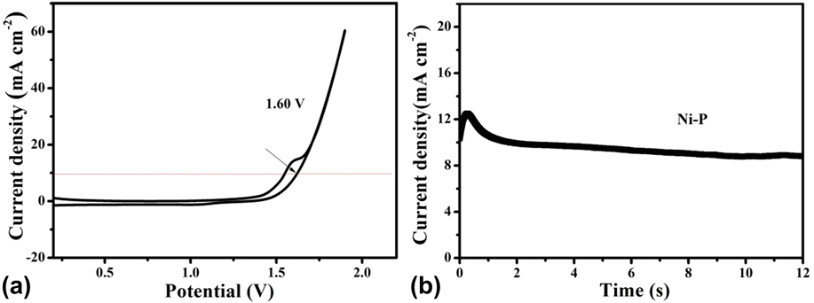
FIG. 8. (a) CV curve and (b) Chronoamperometric curves at 1.6 V of water splitting for the Ni–P sample with 2 h of phosphating treatment in a two-electrode configuration.
TABLE II. The electrocatalytic performance of different nickel phosphide for overall water splitting.

IV. CONCLUSIONS
In summary, the biphasic Ni–P nanorods with a rough surface composed of tiny fibers were grown on an acid-treated Ni foam via direct phosphorization of the Ni foam in a tube furnace, where NaH2PO2·H2O provided the phosphorous vapor. The time of phosphating treatment has important influence on the electrochemical activity of active materials. The obtained Ni–P sample with two hours of phosphating treatment exhibits enhanced catalytic performance toward both HER and OER in the alkaline solution because of the large active surface area and small charge transfer resistance. Furthermore, a current density of 10 mA/cm2 can be delivered at a cell voltage of 1.60 V by an efficient water electrolyzer with good stability using the Ni–P 2 h sample as both cathode and anode in an alkaline electrolyte. This work further underlines the promising application of nickel phosphides for the overall water splitting reaction.


