Hostname: page-component-586b7cd67f-gb8f7 Total loading time: 0 Render date: 2024-11-28T01:53:40.537Z Has data issue: false hasContentIssue false

Stability of drawing of microstructured optical fibres

Published online by Cambridge University Press:  27 April 2023

Jonathan J. Wylie*
Affiliation:
Department of Mathematics, City University of Hong Kong, Kowloon, Hong Kong Center for Applied Mathematics and Statistics, New Jersey Institute of Technology, Newark, NJ 07102, USA
Nazmun N. Papri
Affiliation:
Department of Mathematics, City University of Hong Kong, Kowloon, Hong Kong
Yvonne M. Stokes
Affiliation:
School of Mathematical Sciences and Institute for Photonics and Advanced Sensing, The University of Adelaide, SA 5005, Australia
Dongdong He
Affiliation:
School of Science and Engineering, The Chinese University of Hong Kong, Shenzhen, Guangdong, 518172, PR China
*
Email address for correspondence: [email protected]

Abstract

We consider the stability of the drawing of a long and thin viscous thread with an arbitrary number of internal holes of arbitrary shape that evolves due to axial drawing, inertia and surface tension effects. Despite the complicated geometry of the boundaries, we use asymptotic techniques to determine a particularly convenient formulation of the equations of motion that is well-suited to stability calculations. We will determine an explicit asymptotic solution for steady states with (a) large surface tension and negligible inertia, and (b) large inertia. In both cases, we will show that complicated boundary layer structures can occur. We will use linear stability analysis to show that the presence of an axisymmetric hole destabilises the flow for finite capillary number and which answers a question raised in the literature. However, our formulation allows us to go much further and consider arbitrary hole structures or non-axisymmetric shapes, and show that any structure with holes will be less stable than the case of a solid axisymmetric thread. For a solid axisymmetric thread, we will also determine a closed-form expression that delineates the unconditional instability boundary in which case the thread is unstable for all draw ratios. We will determine how the detailed effects of the microstructure affect the stability, and show that they manifest themselves only via a single function that occurs in the stability problem and hence have a surprisingly limited effect on the stability.

Type
JFM Papers
Copyright
© The Author(s), 2023. Published by Cambridge University Press

1. Introduction

Microstructured optical fibres (MOFs) have revolutionised the telecommunications industry and are in the process of revolutionising a number of important sensing applications. By carefully designing the microstructure, one can obtain highly customisable optical properties that are crucial in an extremely broad range of applications (Liu et al. Reference Liu, Tam, Htein, Tse and Lu2017). Fibres can be produced that have extremely low attenuation, dispersion and nonlinear effects that make them especially valuable for a variety of high-accuracy sensing applications. In particular, MOFs have been used successfully to make high-accuracy measurements of pressure, tension, strain and other physical quantities. They have also been used to detect the presence of various gases. MOFs can also be designed for the delivery of laser beams over distances of several kilometres, which would be infeasible using conventional optical fibres. However, fabricating the sometimes complicated microstructure to within the required tolerances to achieve the optical objectives can be extremely difficult. This is one of the reasons why MOFs remain the subject of very active research.

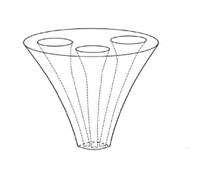
MOFs are typically manufactured by feeding a relatively large preform with holes through an aperture and pulling using a take-up roller at a location a fixed distance away from the aperture. By spinning the take-up roller sufficiently rapidly, the thread can be stretched to achieve the tiny diameters that are required in many of the above-mentioned applications. The relative reduction in the diameter between the input aperture and the take-up roller is determined by the so-called ‘draw ratio’, which is defined as the ratio of the speed of the take-up roller to the feeding speed through the aperture. This process is depicted in figure 1.

Figure 1. Schematic of the thread drawing process.

The earliest theoretical work considering the drawing of threads dates back to Matovich & Pearson (Reference Matovich and Pearson1969) and Pearson & Matovich (Reference Pearson and Matovich1969), who considered a solid axisymmetric thread (i.e. without internal holes) and derived a one-dimensional model. They used linear stability analysis to show that the stretching process is unstable if the draw ratio exceeds a critical value. This instability is one of the most important features of such flows, and is referred to as ‘draw resonance’ (Denn Reference Denn1980). For solid axisymmetric threads, this work has been extended to include the effects of inertia, surface tension, gravity and heating by various authors (Shah & Pearson Reference Shah and Pearson1972a,Reference Shah and Pearsonb; Geyling Reference Geyling1976; Geyling & Homsy Reference Geyling and Homsy1980; Yarin Reference Yarin1986; Forest & Zhou Reference Forest and Zhou2001; Wylie, Huang & Miura Reference Wylie, Huang and Miura2007; Suman & Kumar Reference Suman and Kumar2009; Taroni et al. Reference Taroni, Breward, Cummings and Griffiths2013). Although this problem has a long history, it remains an active area of research, and important new stability results have been obtained by Bechert & Scheid (Reference Bechert and Scheid2017) and Philippi et al. (Reference Philippi, Bechert, Chouffart, Waucquez and Scheid2022), who showed that the combined effects of surface tension, inertia and gravity can give rise to non-monotonic stability behaviour, and that surface tension can completely destabilise the flow. All of these studies considered the stability of axisymmetric thread with no internal holes. Many previous studies have considered surface tension to be a secondary effect in the drawing of solid threads. However, Bechert (Reference Bechert2017) showed that there are a number of important applications in which surface tension can play an important effect in destabilising the drawing of solid threads. Moreover, we will show that surface tension can play an even stronger role for MOFs that can have very large total surface area as a result of their complicated internal structure. This is particularly true for MOFs that have kagome lattice structures in which the area fraction of the glass may be less than 10 % (Argyros & Pla Reference Argyros and Pla2007).

The application to MOFs of mathematical modelling techniques similar to those described above was first considered by Fitt et al. (Reference Fitt, Furusawa, Monro and Please2001Reference Fitt, Furusawa, Monro, Please and Richardson2002) who built on the work of Yarin, Gospodinov & Roussinov (Reference Yarin, Gospodinov and Roussinov1994). Fitt et al. (Reference Fitt, Furusawa, Monro, Please and Richardson2002) considered an axisymmetric fibre with a single hole and quantified how the MOF fabrication process depends on the various parameters that control the various physical mechanisms. In terms of steady states, they found that the results of their model agreed remarkably well with experiments. In terms of stability, they noted that if inertia, gravity, surface tension and internal hole pressurisation are ignored, then the stability results for a capillary are identical to the stability results for a solid thread. They also noted that it was known that surface tension destabilises a solid fibre, but that the role of surface tension in the case of a capillary was unclear. As far as we are aware, this issue has not been addressed in the literature, and this is one of the main motivations of this paper.

All of the work described above was for axisymmetric threads. Fitt et al. (Reference Fitt, Furusawa, Monro, Please and Richardson2002) noted that any theory that considers a large number of arbitrarily arranged holes is significantly more challenging than the axisymmetric case. One possible way to address this challenge is via direct numerical simulations. This has been pursued by Xue et al. (Reference Xue, Large, Barton, Tanner, Polidian and Lwin.2005a,Reference Xue, Tanner, Barton, Lwin, Large and Polidianb,Reference Xue, Tanner, Barton, Lwin, Large and Polidianc), who used sophisticated numerical techniques to study MOFs with up to four holes. However, this approach is extremely difficult and computationally out of reach for the complex structures required in modern MOFs that typically have many more holes. However, having large numbers of holes is imperative to modern MOF fabrication, therefore it is important to face up to this challenge. Non-axisymmetric threads have been studied by Dewynne, Howell & Wilmott (Reference Dewynne, Howell and Wilmott1994), who considered a thread without internal holes but with a non-axisymmetric boundary in the case of negligible surface tension. They showed that at leading order in the aspect ratio, the initial cross-sectional shape of the thread is preserved but reduced in size as a result of the stretching process. The effects of surface tension were included by Cummings & Howell (Reference Cummings and Howell1999) for solid threads, and for thin walled viscous tubes with a single hole by Griffiths & Howell (Reference Griffiths and Howell2007Reference Griffiths and Howell2008). The steady-state problem with a large number of arbitrarily arranged holes was solved by Stokes et al. (Reference Stokes, Buchak, Crowdy and Ebendorff-Heidepriem2014). They developed a method to readily solve the problem for complicated structures that are far beyond what can be solved using direct numerical simulation. This approach has been generalised to consider internal pressurisation of holes (Chen et al. Reference Chen, Stokes, Buchak, Crowdy and Ebendorff-Heidepriem2015), the inverse problem of designing the die for a desired output thread (Buchak et al. Reference Buchak, Crowdy, Stokes and Ebendorff-Heidepriem2015), and explicit thermal effects (Stokes, Wylie & Chen Reference Stokes, Wylie and Chen2019). A similar approach has also been used to consider gravitational extension (Tronnolone et al. Reference Tronnolone, Stokes, Foo and Ebendorff-Heidepriem2016) and extrusion (Tronnolone, Stokes & Ebendorff-Heidepriem Reference Tronnolone, Stokes and Ebendorff-Heidepriem2017). The asymptotic techniques applied in studies of this type have been shown to be accurate by Chen et al. (Reference Chen, Stokes, Buchak, Crowdy and Ebendorff-Heidepriem2016). All of these studies were focused on the steady states and did not consider the stability problem for the drawing of non-axisymmetric threads.

We note that there is an extensive literature on the stability, nonlinear dynamics and pinching of uniform threads that are not subjected to drawing. Pioneering works in this field include Eggers (Reference Eggers1993) and Papageorgiou (Reference Papageorgiou1995), and a nice summary of results can be found in Eggers & Villermaux (Reference Eggers and Villermaux2008). However, the focus of these types of studies is quite different to the focus of studies on fibre drawing. In the latter, one of the key concerns is draw resonance that involves a feedback between the nozzle and the exit of the device, and does not occur in threads that are not subjected to drawing.

In this paper, we use asymptotic techniques to develop a new formulation of the problem that will allow us to compute directly the stability of a thread with arbitrary shape. We include the effects of viscous stresses, surface tension and inertia. For simplicity, we assume constant temperature and do not consider the pressurisation of holes. Although this problem appears to be extremely complicated, we will reduce it to solving a standard Stokes problem for the evolution in the direction transverse to the flow, and then solving a set of three coupled ordinary differential equations to obtain the steady state. We will use this formulation to derive explicit asymptotic expressions for steady states with either large surface tension and negligible inertia, or large inertia. In these asymptotic limits, we will show that complicated boundary layer structures can occur. Our formulation is particularly well-suited to stability calculations since the growth rate for instability can be determined by solving a one-dimensional eigenvalue problem. It will allow us to obtain a closed-form expression that determines the region of unconditional instability for a solid axisymmetric thread. Moreover, our approach allows us to address directly the question raised by Fitt et al. (Reference Fitt, Furusawa, Monro, Please and Richardson2002) regarding the role of surface tension in modifying the draw resonance phenomenon in the case of an axisymmetric thread with a capillary. In particular, we show that the presence of an axisymmetric hole is always destabilising if surface tension is non-negligible. However, our formulations allow us to go much further and consider arbitrary hole structures or non-axisymmetric shapes. We will show that the complicated details of the microstructure can affect the steady states and the stability only via a single monotonic function that can be determined by solving the classical Stokes flow problem. This will allow us to discuss the detailed mechanisms by which the microstructure affects the steady-state behaviour and the stability.

2. Model formulation

2.1. Full three-dimensional model

We consider a drawing device that feeds a thread of a viscous fluid through an aperture with a constant speed $U_{in}$. When it passes through the aperture, the thread has a pattern of $N$ internal air channels (see figure 1). We denote the square root of the cross-sectional area of the fluid as it comes through the aperture as $\chi _{in}$. At a distance $L$ from the aperture, the thread is pulled by a take-up roller such that the thread has speed $U_{out}$.

We denote the time as $t$ and define a coordinate system with the $x$-axis directed along the axis of the thread. We take $x=0$ to be the location of the aperture, and $y$ and $z$ to be the coordinates in the cross-sectional plane. We denote the velocity vector and pressure by ${\boldsymbol {u}}=(u,v,w)$ and $p$, respectively. We denote the shape of the external boundary of the thread by $G^{(0)}(x,y,z,t)=0$, and the shape of each of the $N$ internal holes to be $G^{(i)}(x,y,z,t)=0$, for $i=1,2,\ldots,N$. The outward-pointing normal vectors on the boundaries are hence denoted by $\boldsymbol {n}^{(i)}=\boldsymbol {\nabla } G^{(i)}/|\boldsymbol {\nabla } G^{(i)}|$. For convenience, we also define $\chi ^2(x,t)$ and $\varGamma (x,t)$ to be the area of the cross-section and its total boundary length at axial position $x$, respectively. When the fluid passes through the aperture, the velocity is $u=U_{in}$. At the aperture, the shapes of the external boundary and the internal holes are denoted by $G^{(0)}_{in}(y,z)=0$ and $G^{(i)}_{in}(y,z)=0$, respectively.

Assuming an incompressible Newtonian fluid, the governing equations that represent the conservation of mass and momentum are

(2.1a)\begin{gather} \boldsymbol{\nabla}\boldsymbol{\cdot}\boldsymbol{u}=0, \end{gather}
(2.1b)\begin{gather}\rho\left(\frac{\partial\boldsymbol{u}}{\partial t}+ \boldsymbol{u}\boldsymbol{\cdot} \boldsymbol{\nabla}\boldsymbol{u}\right) ={-}\boldsymbol{\nabla} p+\mu\,\nabla^2\boldsymbol{u} , \end{gather}

where $\rho$ is the density of the fluid, and $\mu$ is the viscosity of the fluid.

On the external surface of the cylinder and on the $N$ internal surfaces, the dynamic and kinematic boundary conditions are

(2.1c)\begin{gather} \boldsymbol{\sigma}\boldsymbol{\cdot}\boldsymbol{n}^{(i)} ={-}\gamma\kappa^{(i)}\boldsymbol{n}^{(i)},\quad i=0,1,\ldots,N, \end{gather}
(2.1d)\begin{gather}\frac{\partial G^{(i)}}{\partial t}+\boldsymbol{u}\boldsymbol{\cdot}\boldsymbol{\nabla} G^{(i)}=0,\quad i=0,1,\ldots N, \end{gather}

where $\boldsymbol {\sigma }$ is the stress tensor, $\gamma$ is the surface tension coefficient, and $\kappa ^{(i)}$ is the local curvature of the $i$th boundary. At the exit of the device, the speed of the thread is controlled by the take-up roller and hence given by $u=U_{out}$ at $x=L$. We note that if we were solving the full three-dimensional problem, we would require additional boundary conditions on $v$ and $w$ at the entrance and exit. However, we will develop long-wavelength equations to describe the flow for which the leading-order equations do not contain derivatives in the $y$ and $z$ directions. We therefore will not need such conditions for our study. At the input and exit, there will be thin boundary layers in which the solutions to the long-wavelength equations adjust rapidly to accommodate the neglected boundary conditions. This is a common feature of mathematical studies that exploit the slenderness of the thread to solve drawing problems.

In what follows, we will use techniques similar to those developed by Stokes et al. (Reference Stokes, Buchak, Crowdy and Ebendorff-Heidepriem2014) to decouple the axial and transverse flow. However, in our approach, we will derive a system of equations that is particularly well-suited to stability calculations and hence will allow us to readily obtain results about the stability of drawing.

2.2. Non-dimensionalisation

We non-dimensionalise the axial length scale using $L$, which represents the distance between the aperture and the take-up roller. We non-dimensionalise the radial length scales using $\chi _{in}$, which represents the square root of the cross-sectional area at the aperture. We then select the natural scales

(2.2)\begin{equation} \left.\begin{array}{c@{}} (x,y,z)=L(x',\epsilon y',\epsilon z'), \quad t=\dfrac{L}{U_{in}}\,t',\quad p=\dfrac{\mu U_{in}}{L}\,p',\\ (u,v,w)=U_{in}(u',\epsilon v',\epsilon w'),\quad \chi=\chi_{in}\chi',\quad \varGamma=\chi_{in} \varGamma', \quad \kappa={\kappa'}/{\chi_{in}}, \end{array}\right\} \end{equation}

where primes denote dimensionless variables, and

(2.3)\begin{equation} \epsilon=\frac{\chi_{in}}{L} \end{equation}

is the slenderness parameter.

We next substitute these expressions into the governing equations, and drop the primes for convenience. The momentum equation (2.1b) yields

(2.4a)\begin{gather} {Re}\,\epsilon^2\left( \frac{\partial u}{\partial t}+ u\,\frac{\partial u}{\partial x}+v\,\frac{\partial u}{\partial y}+w\,\frac{\partial u}{\partial z}\right)={-}\epsilon^2\,\frac{\partial p}{\partial x} +\epsilon^2\,\frac{\partial^2 u}{\partial x^2}+\frac{\partial^2 u}{\partial y^2} +\frac{\partial^2 u}{\partial z^2}, \end{gather}
(2.4b)\begin{gather}{Re}\,\epsilon^2\left( \frac{\partial v}{\partial t}+ u\,\frac{\partial v}{\partial x}+v\,\frac{\partial v}{\partial y}+w\,\frac{\partial v}{\partial z}\right)={-}\frac{\partial p}{\partial y} +\epsilon^2\,\frac{\partial^2 v}{\partial x^2}+\frac{\partial^2 v}{\partial y^2}+\frac{\partial^2 v}{\partial z^2}, \end{gather}
(2.4c)\begin{gather}{Re}\,\epsilon^2\left( \frac{\partial w}{\partial t}+ u\,\frac{\partial w}{\partial x}+v\,\frac{\partial w}{\partial y}+w\,\frac{\partial w}{\partial z}\right)={-}\frac{\partial p}{\partial z} +\epsilon^2\,\frac{\partial^2 w}{\partial x^2}+\frac{\partial^2 w}{\partial y^2}+\frac{\partial^2 w}{\partial z^2}, \end{gather}

where

(2.5)\begin{equation} {Re}=\frac{\rho U_{in} L}{\mu} \end{equation}

is the Reynolds number. The continuity equation (2.1a) yields

(2.6)\begin{equation} \frac{\partial u}{\partial x}+\frac{\partial v}{\partial y} +\frac{\partial w}{\partial z}=0.\end{equation}

The boundary conditions (2.1c) are given by

(2.7a)\begin{gather} \epsilon^2 \left({-}p+2\,\frac{\partial u}{\partial x}\right)n_x^{(i)}+\left(\frac{\partial u}{\partial y}+\epsilon^2\,\frac{\partial v}{\partial x}\right)n_y^{(i)}+ \left(\frac{\partial u}{\partial z}+\epsilon^2\,\frac{\partial w}{\partial x}\right)n_z^{(i)} ={-}\frac{\epsilon^2}{{Ca}}\,\kappa^{(i)} n_x^{(i)}, \end{gather}
(2.7b)\begin{gather}\left({-}p+2\,\frac{\partial v}{\partial y}\right)n_y^{(i)}+ \left(\epsilon^2\,\frac{\partial v}{\partial x}+\frac{\partial u}{\partial y}\right)n_x^{(i)} +\left(\frac{\partial v}{\partial z}+\frac{\partial w}{\partial y}\right)n_z^{(i)} ={-}\frac{1}{{Ca}}\,\kappa^{(i)} n_y^{(i)}, \end{gather}
(2.7c)\begin{gather}\left({-}p+2\,\frac{\partial w}{\partial z}\right)n_z^{(i)}+\left(\epsilon^2\,\frac{\partial w}{\partial x}+\frac{\partial u}{\partial z}\right)n_x^{(i)} +\left(\frac{\partial v}{\partial z}+\frac{\partial w}{\partial y}\right)n_y^{(i)} ={-}\frac{1}{{Ca}}\,\kappa^{(i)} n_z^{(i)}, \end{gather}

where

(2.8)\begin{equation} {Ca}=\frac{\mu U_{in}\chi_{in}}{\gamma L} \end{equation}

is the effective capillary number. The kinematic conditions (2.1d) are invariant under the scaling and are hence given by

(2.9)\begin{equation} \frac{\partial G^{(i)}}{\partial t}+ u\,\frac{\partial G^{(i)}}{\partial x}+v\,\frac{\partial G^{(i)}}{\partial y}+w\,\frac{\partial G^{(i)}}{\partial z}=0. \end{equation}

The boundary conditions at the aperture $x=0$ are given by

(2.10)\begin{equation} u=1,\quad v=w=0\quad \text{and}\quad \chi=1,\end{equation}

whereas the boundary conditions at the take-up roller at $x=1$ are given by

(2.11)\begin{equation} u=D,\quad v=w=0,\end{equation}

where

(2.12)\begin{equation} D=\frac{U_{out}}{U_{in}}\end{equation}

is the draw ratio.

Parameters in fibre drawing can vary dramatically depending upon the material properties of the fluid and the specifications of the device that is being used. This is because large-scale drawing in industrial settings is often performed at dramatically different speeds and length scales than small-scale drawing in laboratory settings. Moreover, the viscosity can differ over many orders of magnitude, depending on the material that is used and the temperature at which the drawing process takes place. A detailed discussion of the ranges of parameters that can occur can be found in Bechert (Reference Bechert2017). He showed that the slenderness parameter $\epsilon$ is typically at most $O(10^{-1})$ and can be much smaller. On the other hand, in order to embrace the whole range of settings, it is important to consider a broad range of both small and large Reynolds and capillary numbers. The draw ratio $D$ is usually chosen to be as large as possible, and one of the aims of this paper is to understand over what range of $D$ stable drawing can be performed.

2.3. Long-wavelength approximation

As is typical in the modelling of fibre drawing problems (Yarin et al. Reference Yarin, Rusinov, Gospodinov and Radev1989; Kaye Reference Kaye1991; Dewynne et al. Reference Dewynne, Ockendon and Wilmott1992; Dewynne et al. Reference Dewynne, Howell and Wilmott1994; Cummings & Howell Reference Cummings and Howell1999; Stokes, Tuck & Schwartz Reference Stokes, Tuck and Schwartz2000; Fitt et al. Reference Fitt, Furusawa, Monro, Please and Richardson2002; Stokes & Tuck Reference Stokes and Tuck2004; Bradshaw-Hajek et al. Reference Bradshaw-Hajek, Stokes and Tuck2007; Wylie & Huang Reference Wylie and Huang2007; Wylie et al. Reference Wylie, Huang and Miura2007; Griffiths & Howell Reference Griffiths and Howell2008; Stokes et al. Reference Stokes, Bradshaw-Hajek and Tuck2011; Wylie et al. Reference Wylie, Huang and Miura2011; Taroni et al. Reference Taroni, Breward, Cummings and Griffiths2013; Stokes et al. Reference Stokes, Buchak, Crowdy and Ebendorff-Heidepriem2014; Wylie et al. Reference Wylie, Huang and Miura2015; He et al. Reference He, Wylie, Huang and Miura2016; Wylie et al. Reference Wylie, Bradshaw-Hajek and Stokes2016), we exploit the fact that $\epsilon \ll 1$ to develop long-wavelength equations that are significantly simpler to deal with than the full equations given above. Thus we expand all dependent variables in powers of $\epsilon ^2$,

(2.13)\begin{equation} \left. \begin{array}{c@{}} u=u_0(x,y,z)+\epsilon^2\,u_1(x,y,z) +\epsilon^4\,u_2(x,y,z)+\cdots,\\ v=v_0(x,y,z)+\epsilon^2\,v_1(x,y,z) +\epsilon^4\,v_2(x,y,z)+\cdots, \end{array}\right\} \end{equation}

with similar expressions for $w$, $p$, $G^{(i)}$, $\kappa ^{(i)}$, $\chi$ and $\varGamma ^{(i)}$. These expressions are then substituted into (2.4), (2.6), (2.7), (2.9)–(2.11). With the additional assumption $\epsilon ^2{Re}\ll 1$, the leading-order momentum equation and boundary conditions are then

(2.14a)\begin{gather} \nabla_\perp^2 u_0=0, \end{gather}
(2.14b)\begin{gather}\boldsymbol{\nabla}_\perp u_0\boldsymbol{\cdot} {\boldsymbol{n}}_\perp^{(i)}=0\quad \mbox{for $i=0,1,\ldots,N,$} \end{gather}

where $\boldsymbol {\nabla }_\perp =(\partial /\partial y,\partial /\partial z)$, and $\boldsymbol {n}^{(i)}_\perp =(n_y^{(i)},n_z^{(i)})$. From (2.14b), we deduce immediately that $u_0=u_0(x,t)$, that is, the leading-order axial velocity is independent of the cross-plane position.

2.4. Leading-order axial flow model

At $O(\epsilon ^0)$, (2.4) for the axial velocity component yields $u_0=u_0(x,t)$. In order to obtain an equation that $u_0(x,t)$ satisfies, we need to consider $O(\epsilon ^2)$ terms from this equation. This yields

(2.15a)\begin{equation} \boldsymbol{\nabla}_\perp\boldsymbol{\cdot} (\boldsymbol{\nabla}_\perp u_1)={Re} \left(\frac{\partial u_0}{\partial t}+ u_0\,\frac{\partial u_0}{\partial x} \right)+\frac{\partial p_0}{\partial x} -\frac{\partial^2 u_0}{\partial x^2},\end{equation}

with boundary conditions

(2.15b)\begin{equation} \boldsymbol{\nabla}_\perp u_1={-}\frac{\partial v_0}{\partial x}\,n_y^{(i)}- \frac{\partial w_0}{\partial x}\,n_z^{(i)} +\left(p_0-2\,\frac{\partial u_0}{\partial x}\right)n_x^{(i)} -\frac{1}{{Ca}}\,\kappa_0^{(i)} n_x^{(i)}.\end{equation}

Following a procedure developed by Dewynne et al. (Reference Dewynne, Howell and Wilmott1994) and Cummings & Howell (Reference Cummings and Howell1999), (2.15a) and the boundary conditions (2.15b) are effectively integrated over the cross-sectional area to obtain the axial force balance equation

(2.16)\begin{equation} -{Re}\,\chi_0^2 \left(\frac{\partial u_0}{\partial t}+ u_0\,\frac{\partial u_0}{\partial x} \right) +\frac{\partial}{\partial x}\left(3\chi_0^2\, \frac{\partial u_0}{\partial x}\right) +\frac{1}{2\,{Ca}}\,\frac{\partial\varGamma_0}{\partial x}=0.\end{equation}

Similarly, the continuity equation (2.6) and the kinematic condition (2.9) are effectively integrated over the cross-sectional area to obtain

(2.17)\begin{equation} \frac{\partial }{\partial t} (\chi_0^2)+ \frac{\partial}{\partial x}(u_0\chi_0^2 )=0.\end{equation}

In general, the leading-order total boundary length of the cross-section, $\varGamma _0(x,t)$, that appears in (2.16) must be obtained by solving for the flow in the cross-section.

2.5. Leading-order transverse flow model

The equations for the flow in the cross-section are obtained by taking the leading-order terms from the continuity and transverse flow equations, and are given by

(2.18a)\begin{gather} \frac{\partial v_0}{\partial y}+\frac{\partial w_0}{\partial z}={-}\frac{\partial u_0}{\partial x}, \end{gather}
(2.18b)\begin{gather}-\frac{\partial p_0}{\partial y}+2\,\frac{\partial^2 v_0}{\partial y^2}+ \frac{\partial^2 v_0}{\partial z^2}+\frac{\partial^2 w_0}{\partial y\partial z}=0, \end{gather}
(2.18c)\begin{gather}-\frac{\partial p_0}{\partial z}+\frac{\partial^2 w_0}{\partial y^2}+\frac{\partial^2 v_0}{\partial y \partial z}+2\,\frac{\partial^2 w_0}{\partial z^2}=0, \end{gather}

with boundary conditions

(2.18d)\begin{gather} \left({-}p_0+2\,\frac{\partial v_0}{\partial y}\right)n_y^{(i)}+ \left(\frac{\partial v_0}{\partial z}+\frac{\partial w_0}{\partial y}\right)n_z^{(i)}= \frac{1}{{Ca}}\,(-\kappa_0^{(i)} n_y^{(i)}), \end{gather}
(2.18e)\begin{gather}\left({-}p_0+2\,\frac{\partial w_0}{\partial z}\right)n_z^{(i)}+ \left(\frac{\partial v_0}{\partial z}+ \frac{\partial w_0}{\partial y}\right)n_y^{(i)} = \frac{1}{{Ca}}\,(-\kappa_0^{(i)} n_z^{(i)}), \end{gather}
(2.18f)\begin{gather}\frac{\partial G_0^{(i)}}{\partial t} + u_0\,\frac{\partial G_0^{(i)}}{\partial x}+ v_0\,\frac{\partial G_0^{(i)}}{\partial y}+ w_0\,\frac{\partial G_0^{(i)}}{\partial z} =0 \end{gather}

for $i=0,\ldots,N$.

Equations (2.18) must be solved in conjunction with (2.16) and (2.17). These equations are coupled since (2.18) depends on $u_0$, while (2.16) depends on $\varGamma _0(x,t)$. However, we will show that the transverse flow (2.18) can be decoupled from (2.16) and (2.17) by making the series of transformations described below.

2.6. Decoupling the leading-order transverse flow model

In the above formulation, the transverse flow model (2.18) depends on the axial flow $u_0$ and the capillary number ${Ca}$. Moreover, as a result of the axial stretching, the cross-sectional area varies as a function of the axial position. However, in this subsection, we will use a series of transformations that achieves three objectives: first, to decouple the transverse flow model from the axial flow; second, to rescale such that the effective capillary number in the scaled variables is unity; and third, to rescale the cross-section such that the cross-sectional area remains constant. In order to do this, we begin by following the procedure used by Cummings & Howell (Reference Cummings and Howell1999), Dewynne et al. (Reference Dewynne, Howell and Wilmott1994) and Stokes et al. (Reference Stokes, Buchak, Crowdy and Ebendorff-Heidepriem2014), and write the flow in the cross-section as the sum of the solution in the absence of surface tension and a component due to the surface tension, namely,

(2.19a,b)\begin{equation} p_0={-}\frac{\partial u_0}{\partial x}+\frac{1}{{Ca}\,\chi_0}\,\tilde{p},\quad (v_0,w_0)={-}\frac{1}{2}\,\frac{\partial u_0}{\partial x}(y,z)+\frac{1}{{Ca}}\,(\tilde{v},\tilde{w}). \end{equation}

Here, $\tilde {p}$, $\tilde {v}$ and $\tilde {w}$ represent the scaled deformation due to surface tension. The scalings $1/({Ca}\,\chi _0)$ and $1/{Ca}$ in (2.19a,b) are selected to rescale such that the effective capillary number in the resulting cross-plane flow problem is unity.

We can express (2.18f) in terms of a Lagrangian derivative in which fluid elements are transported with the leading-order velocity in the $x$ direction to obtain

(2.20)\begin{equation} \frac{{\rm D} G_0^{(i)}}{{\rm D} t} + v_0\frac{\partial G_0^{(i)}}{\partial y}+ w_0\frac{\partial G_0^{(i)}}{\partial z} =0. \end{equation}

We next define a variable $\tau$ that tracks the scaled time that a particular cross-section has spent in the device:

(2.21)\begin{equation} \frac{{\rm D} \tau}{{\rm D} t}=\frac{1}{\chi_0\,{Ca}},\quad\text{with}\ \tau=0\ \text{at}\ x=0. \end{equation}

For initial value problems, we would also need to specify the value of $\tau$ for $x\in (0,1)$ at $t=0$, but in this paper we are focusing on stability, so any initial transients are not of interest and we need only the boundary condition at $x=0$. The purpose of this transformation is that it will remove the explicit dependence on $u_0$ from the resulting cross-plane flow problem.

In order to rescale the cross-section such that the cross-sectional area remains constant for all values of $x$, we scale the transverse coordinates and boundary lengths with $\chi _0(\tau )$ so that

(2.22ac)\begin{equation} (y,z)=\chi_0(\tilde{y},\tilde{z}),\quad \varGamma^{(i)}_0=\chi_0\tilde\varGamma^{(i)}_0,\quad \tilde{\kappa}^{(i)}=\chi_0\kappa^{(i)}. \end{equation}

Using these transformations and subtracting the zero surface tension eigensolution (Cummings & Howell Reference Cummings and Howell1999), we obtain

(2.23a)\begin{gather} \tilde{v}_{\tilde{y}}+\tilde{w}_{\tilde{z}} = 0, \end{gather}
(2.23b)\begin{gather}\tilde{v}_{\tilde{y}\tilde{y}}+\tilde{v}_{\tilde{z}\tilde{z}} = \tilde{p}_{\tilde{y}}, \end{gather}
(2.23c)\begin{gather}\tilde{w}_{\tilde{y}\tilde{y}}+\tilde{w}_{\tilde{z}\tilde{z}} = \tilde{p}_{\tilde{z}}, \end{gather}
(2.23d)\begin{gather}\frac{{\rm D}G^{(i)}}{{\rm D}\tau}+\tilde{v}G_{\tilde{y}}^{(i)} +\tilde{w}G_{\tilde{z}}^{(i)} = 0 \quad\mbox{on}\ G^{(i)}(\tau,\tilde y,\tilde z)=0, \end{gather}
(2.23e)\begin{gather}G_{\tilde{y}}^{(i)}(-\tilde{p}+2\tilde{v}_{\tilde{y}}) +G_{\tilde{z}}^{(i)}(\tilde{v}_{\tilde{z}}+\tilde{w}_{\tilde{y}}) ={-}\tilde{\kappa}G_{\tilde{y}}^{(i)}, \quad\mbox{on}\ G^{(i)}(\tau,\tilde y,\tilde z)=0, \end{gather}
(2.23f)\begin{gather}G_{\tilde{y}}^{(i)}(\tilde{v}_{\tilde{z}}+\tilde{w}_{\tilde{y}}) +G_{\tilde{z}}^{(i)}(-\tilde{p}+2\tilde{w}_{\tilde{z}}) ={-}\tilde{\kappa}G_{\tilde{z}}^{(i)}, \quad\mbox{on}\ G^{(i)}(\tau,\tilde y,\tilde z)=0, \end{gather}

where subscripts denote differentiation with respect to the subscript variables.

One can see clearly that the set of transformations has achieved the three stated objectives, and the modified equations for the transverse flow (2.23a)–(2.23f) are independent of $u_0$, independent of ${Ca}$, and conserve the scaled cross-sectional area. In fact, (2.23a)–(2.23f) form the classical two-dimensional surface-tension-driven Stokes flow free boundary problem on a domain of unit area driven by unit surface tension on the boundary. This has been studied widely, and can be solved by using an extremely wide range of techniques that have been designed for this classical problem. These include boundary integral techniques and spectral methods. In addition, complex variable techniques have been developed that can give analytical or semi-analytical solutions in some cases.

Having used one of the above-mentioned methods to obtain the solution, we can readily extract the scaled total boundary length $\tilde {\varGamma }_0$ as a function of $\tau$ only. This function $\tilde {\varGamma }_0(\tau )$ depends only on the geometric structure of the holes at the time when the thread enters through the aperture, and hence depends only on the boundary condition at the aperture. Having solved for the scaled boundary length $\tilde {\varGamma }_0(\tau )$, one can then use (2.22ac) to obtain the unscaled boundary length $\varGamma _0=\chi _0\,\tilde {\varGamma }_0(\tau )$.

2.7. Simplified equations for the cross-sectional area

Having obtained $\tilde {\varGamma }_0(\tau )$, our system that describes the axial flow problem (2.16), (2.17) and (2.21) can be reduced to the following three partial differential equations:

(2.24)\begin{gather} -{Re}\,\chi_0^2 \left(\frac{\partial u_0}{\partial t}+ u_0\,\frac{\partial u_0}{\partial x} \right) +\frac{\partial}{\partial x}\left(3\chi_0^2\, \frac{\partial u_0}{\partial x}\right) +\frac{1}{2\,{Ca}}\,\frac{\partial}{\partial x} (\chi_0\,\tilde{\varGamma}_0(\tau))=0, \end{gather}
(2.25)\begin{gather}\frac{\partial }{\partial t} (\chi_0^2)+ \frac{\partial}{\partial x}(u_0\chi_0^2 )=0, \end{gather}
(2.26)\begin{gather}\frac{\partial\tau}{\partial t}+u_0\,\frac{\partial\tau}{\partial x}=\frac{1}{\chi_0\,{Ca}}. \end{gather}

The boundary conditions are $u_0=1$, $\tau =0$ and $\chi _0=1$ at $x=0$, and $u_0=D$ at $x=1$.

Unlike previous formulations of the fibre drawing problem, in which the advective derivatives in (2.24) and (2.25) are written in terms of the Lagrangian variable $\tau$, we use the Eulerian form of the derivatives. The formulation (2.24)–(2.26) is convenient for determining the stability for the following reasons. It has the advantages of a Lagrangian formulation in that the cross-flow problem decouples from the axial problem and all of the information required from the cross-flow problem can represented by a function of $\tau$ given by $\tilde \varGamma _0(\tau )$ that is independent of any perturbations that we consider. It also has the advantages of the Eulerian scheme in that one can easily determine the stability to high accuracy using standard numerical techniques.

Before continuing to analyse the equations, we note that $\tilde \varGamma _0(\tau )$ is not a completely arbitrary function, and there are a number of important properties that it must have. First, the scaled transverse flow problem must eventually evolve to the shape of minimal curvature that is given by an axisymmetric solid thread. Since the scaled cross-sectional area is conserved and is scaled to be unity, this means that the eventual shape must tend towards a circle with unit cross-sectional area. Such a circle has radius $1/\sqrt {{\rm \pi} }$ and circumference $2\sqrt {{\rm \pi} }$. Hence the scaled total boundary length satisfies $\tilde \varGamma _0(\tau )\to 2\sqrt {{\rm \pi} }$ as $\tau \to \infty$. Second, in the rescaled transverse flow problem, there is no apparent external force, so the surface tension will always act to reduce the total surface energy. This is equivalent to reducing the total boundary length, therefore we can can conclude that $\tilde \varGamma _0(\tau )$ must be a monotonic decreasing function of $\tau$. Therefore, the presence of holes can affect the stability in only a somewhat restricted way. Namely, the presence of holes can manifest itself only via a monotonic decreasing function that is bounded below. For this reason, we can understand the main mechanisms by studying a small number of simple cases. One additional feature to notice is that, roughly speaking, the more complicated the structure of the holes, the more quickly the surface tension will act, so $\tilde \varGamma _0(\tau )$ will decay to $2\sqrt {{\rm \pi} }$ more quickly. We illustrate this by considering two cases for the initial shape: a case with four holes, and a case of a single axisymmetric hole (see figure 2). For the purposes of comparison, we choose the size of the holes so that both cases have the same initial boundary length. We make this choice because the details of the cross-section appear in the axial momentum equation only via the total scaled boundary length. So by choosing two examples that have the same initial boundary length but different internal structure, we can address the important question of what role the internal structure plays in determining the flow dynamics. In figure 3, we show that $\tilde \varGamma _0(\tau )$ decreases more rapidly for a case with four holes when compared with the case of a single axisymmetric hole with the same initial boundary length. Figure 3 therefore provides a concrete example to illustrate that $\tilde \varGamma _0(\tau )$ decreases more rapidly for more complicated structures. The derivation of the results shown in figure 3 for the case with four holes and the single axisymmetric hole will be given in detail in § 5.

Figure 2. The initial shapes that we will consider in this paper. (a) An axisymmetric tube with unit cross-sectional area, outer radius $R_{in}$ and internal radius $\phi_{in}R_{in}$. We consider the special case $\phi_{in}=0.5882$ that has the same total boundary length as the non-axisymmetric example with four internal holes. (b) A circle with four internal holes that has unit cross-sectional area. The ratio of the hole radius to the radius of the outer circle is 0.2. The four holes are equally spaced in such a way that they have a fourfold symmetry with respect to rotations around the centre of the outer circle. The distance between the centre of a hole and the centre of the outer circle is 0.4 times the radius of the outer circle.

Figure 3. The scaled boundary length $\tilde \varGamma _0$ is plotted as a function of $\tau$ for the two initial configurations shown in figure 2. In the case with four holes, the function $\tilde \varGamma _0$ decays more rapidly than in the case of a single axisymmetric hole with the same initial boundary length.

3. Analysis of the model equations

In this section, we analyse the system of equations that describes the axial flow problem (2.24)–(2.26) given the function $\tilde {\varGamma }_0(\tau )$ that comes from the solution to the transverse flow problem. In particular, for steady states we will consider the cases of negligible and large Reynolds number. For negligible Reynolds number, we will determine an implicit asymptotic expression for the solution. For the case in which the capillary number is also small, we will derive an explicit asymptotic solution and show that two boundary layers develop, one near the entrance and another near the exit. For large Reynolds number, we will also determine explicit asymptotic solutions and show that a boundary layer occurs near the exit. These asymptotic solutions provide a good understanding of the importance of the various physical effects that occur in drawing. Having analysed the steady states, we derive the equations that govern the linear stability of the steady states.

3.1. Steady-state solutions

In order to find the steady state, we set $\partial _t\equiv 0$ in (2.24)–(2.26). We can then integrate (2.25) and apply the boundary conditions at $x=0$ to obtain $u_0\chi _0^2=1$ for all $x$. Using this to eliminate $u_0$ from (2.24), we obtain

(3.1)\begin{equation} -{Re}\,\frac{{\rm d}}{{\rm d}\kern0.7pt x}\left(\frac{1}{\chi_0^2}\right) -6\,\frac{{\rm d}}{{\rm d}\kern0.7pt x}\left(\frac{1}{\chi_0}\,\frac{{\rm d} \chi_0}{{\rm d}\kern0.7pt x}\right) +\frac{1}{2\,{Ca}}\,\frac{{\rm d}}{{\rm d}\kern0.7pt x} (\chi_0\,\tilde{\varGamma}_0(\tau))=0. \end{equation}

This can be integrated to yield

(3.2)\begin{equation} \frac{{\rm d} \chi_0}{{\rm d}\kern0.7pt x}={-}T\chi_0+\frac{1}{12\,{Ca}}\,\chi_0^2\,\tilde{\varGamma}_0(\tau) -\frac{{Re}}{6\chi_0}, \end{equation}

where $T$ is a constant of integration that is proportional to the tension in the thread. Eliminating $u_0$ from the steady-state version of (2.26), we obtain

(3.3)\begin{equation} \frac{{\rm d}\tau}{{\rm d}\kern0.7pt x}=\frac{\chi_0}{{Ca}}.\end{equation}

The boundary conditions are $\tau =0$ and $\chi _0=1$ at $x=0$, and $\chi _0=1/\sqrt {D}$ at $x=1$.

3.1.1. Steady-state solutions with negligible inertia

Before presenting numerical results for the steady-state profiles, we derive some analytical expressions and approximations that will allow us to better understand the role that surface tension plays in determining the flow. We next consider the case of zero inertia. In this case, we can find a particularly convenient closed-form solution for the general problem. Using (3.3) and (3.2) with ${Re}=0$, we obtain

(3.4)\begin{equation} \frac{1}{\chi_0}\,\frac{{\rm d} \chi_0}{{\rm d}\kern0.7pt x}={-}T+\frac{1}{12}\,\tilde{\varGamma}_0(\tau)\,\frac{{\rm d} \tau}{{\rm d}\kern0.7pt x}.\end{equation}

This can be integrated with respect to $x$, and after applying the boundary conditions $\tau =0$ and $\chi _0=1$ at $x=0$, we obtain

(3.5)\begin{equation} \chi_0={\rm e}^{{-}Tx}\, {\rm e}^{\frac{1}{12}\int_0^\tau \tilde{\varGamma}_0(y) \,{{\rm d} y} }. \end{equation}

We note that a similar result was obtained by Stokes et al. (Reference Stokes, Buchak, Crowdy and Ebendorff-Heidepriem2014). Substituting this into (3.3), we obtain a separable equation for $\tau$ given by

(3.6)\begin{equation} \frac{{\rm d} \tau}{{\rm d}\kern0.7pt x}=\frac{1}{{Ca}}\, {\rm e}^{{-}Tx}\, {\rm e}^{\frac{1}{12}\int_0^\tau \tilde{\varGamma}_0(y) \,{{\rm d} y} }, \end{equation}

which can be integrated subject to the boundary condition $\tau =0$ at $x=0$ to yield

(3.7)\begin{equation} \int_0^\tau {\rm e}^{-\frac{1}{12}\int_0^{y'} \tilde{\varGamma}_0(y) \,{{\rm d} y} }\, {{\rm d} y}' =\frac{1}{T\,{Ca}}\,(1-{\rm e}^{{-}Tx}).\end{equation}

This represents an implicit expression for $\tau$ in terms of $x$. One can then obtain $\chi _0$ by substituting this expression for $\tau (x)$ into (3.5). Evaluating this expression at $x=1$ and using the boundary condition $\chi _0=D^{-1/2}$ at $x=1$ gives an equation for the constant $T$. Having determined $T$, one can substitute it into (3.5) and (3.7), and hence obtain the steady-state solution. This procedure can be analysed and understood more easily in the case when surface tension is large, that is, ${Ca}\ll 1$. We will pursue this in the next subsubsection.

3.1.2. Steady-state solutions with negligible inertia and large surface tension

We begin by noting that the right-hand side of (3.7) is an increasing function of $T$ that takes the asymptotic form $x/{Ca}$ as $T\to 0$. Hence if $x\gg {Ca}$, then the right-hand side of (3.7) will necessarily be large. This means that the left-hand side of (3.7) must also be large. This can happen only if $\tau$ becomes large. Noting that $\tilde {\varGamma }_0(y)\to 2\sqrt {{\rm \pi} }$ as $y\to \infty$, we rewrite the inner integral on the left-hand side of (3.7) by subtracting and adding $2\sqrt {{\rm \pi} }$ to the integrand to obtain

(3.8)\begin{equation} \int_0^\tau {\rm e}^{-\frac{1}{12}\int_0^{y'} (\tilde{\varGamma}_0(y)-2\sqrt{\rm \pi} )\,{{\rm d} y}}\, {\rm e}^{-({\sqrt{\rm \pi}}/{6})y'}{{{\rm d} y}'}=\frac{1}{T\,{Ca}}\,(1-{\rm e}^{{-}Tx}). \end{equation}

If $\tau$ is large, then for most of the domain of the integral on the left-hand side of (3.7), we can approximate

(3.9)\begin{equation} \frac{1}{12}\int_0^{y'} (\tilde{\varGamma}_0(y)-2\sqrt{\rm \pi} )\,{{\rm d} y}\approx \frac{1}{12}\int_0^{\infty} (\tilde{\varGamma}_0(y)-2\sqrt{\rm \pi} )\,{{\rm d} y}\equiv K.\end{equation}

Under this approximation, one can readily show that

(3.10)\begin{equation} \chi_0=\frac{6\,{Ca}\,T}{\sqrt{\rm \pi}+(6\,{Ca}\,T\,{\rm e}^{{-}K}-\sqrt{\rm \pi}) \, {\rm e}^{Tx}} \end{equation}

as long as $x$ is not in a region of asymptotic width ${Ca}$ near $x=0$. Applying the condition $\chi _0=D^{-1/2}$ at $x=1$, we obtain the condition

(3.11)\begin{equation} D^{{-}1/2}[\sqrt{\rm \pi}+(6\,{Ca}\,T\, {\rm e}^{{-}K}-\sqrt{\rm \pi}) \, {\rm e}^{T}]=6\,{Ca}\,T, \end{equation}

which must be solved for $T$. This clearly requires ${Ca}\,T\, \textrm {e}^{-K}>\sqrt {{\rm \pi} }$, and in fact, for ${Ca}\ll 1$ one can readily see that $6\,{Ca}\,T\, \textrm {e}^{-K}-\sqrt {{\rm \pi} }$ will be exponentially small in $1/{Ca}$. Therefore, we write $6\,{Ca}\,T\, \textrm {e}^{-K}=\sqrt {{\rm \pi} }+\xi$ and after substituting into (3.11), and neglecting terms that are exponentially small in $1/{Ca}$, we obtain $\xi =(D^{1/2}\, \textrm {e}^K-1)\, \textrm {e}^{-(\textrm {e}^K\sqrt {{\rm \pi} })/(6\,{Ca})}$. Substituting into (3.10) yields the asymptotic solution for $\chi _0$ as

(3.12)\begin{equation} \chi_0=\frac{{\rm e}^K}{1+(D^{1/2}\, {\rm e}^K-1) \exp\left(-\dfrac{\sqrt{\rm \pi}\, {\rm e}^K(1-x)}{6\,{Ca}}\right)}, \end{equation}

which is valid only for $x\gg {Ca}$. This shows that as surface tension becomes more important, the variation in the cross-sectional area becomes increasingly focused near the outlet at $x=1$, and there is less thinning over the bulk of the drawing region. For $x\sim {Ca}$, there is a boundary layer in which the value of $\chi _0$ adjusts $\chi _0=1$ to $\textrm {e}^K$. In this region, one can still use the value of $T$ obtained above to substitute into (3.7) and obtain

(3.13)\begin{equation} \int_0^\tau \, {\rm e}^{-\frac{1}{12}\int_0^{y'} \tilde{\varGamma}_0(y)\, {{\rm d} y} }\,{{\rm d} y}' =\frac{6\, {\rm e}^{{-}K}}{\sqrt{\rm \pi}}\left(1-\exp\left(-\frac{\sqrt{\rm \pi}\, {\rm e}^K}{6\,{Ca}}\,x\right)\right). \end{equation}

However, for $x\sim {Ca}$, the right-hand side of (3.13) will be an $O(1)$ quantity, so $\tau$ will also be an $O(1)$ quantity. This means that the asymptotic behaviour in this region depends on the specific nature of the function $\tilde {\varGamma }_0$. Nevertheless, we can use (3.13) to obtain $\tau$ as an implicit function of $x$. Given this expression, one can then use the asymptotic value of $T$ in (3.5) to give an expression for $\chi _0$ that is valid for $x\sim {Ca}$:

(3.14)\begin{equation} \chi_0=\exp\left(-\frac{\sqrt{\rm \pi}\, {\rm e}^K}{6\,{Ca}}\,x+\frac{1}{12}\int_0^\tau \tilde{\varGamma}_0(y)\, {{\rm d} y} \right) . \end{equation}

We note that in the case of a cylindrical thread with no hole, we have $\tilde {\varGamma }_0(y)\equiv 2\sqrt {{\rm \pi} }$, the approximation (3.9) is exact, and $K=0$. This means that there is no boundary layer in the region $x\sim {Ca}$, and the approximation for $\chi _0$ is given by

(3.15)\begin{equation} \chi_0=\frac{1}{1+(D^{1/2}-1) \exp\left(-\dfrac{\sqrt{\rm \pi}(1-x)}{6\,{Ca}}\right)}, \end{equation}

which is valid for all $x$. These results show the way that surface tension induces two boundary layers, one near the entrance and another near the exit. We will compare these expressions with numerical results and discuss the mechanisms underlying this behaviour in § 5.

3.1.3. Steady-state solutions with large inertia

It is also of interest to consider how the presence of inertia affects the steady states. In this case, if ${Ca}$ is $O(1)$ or larger, then the inertial term will always dominate the surface tension term, so the role of the hole structure in determining (3.2) will be negligible. Neglecting the surface tension terms in (3.2), we see that we have an ordinary differential equation of Bernoulli type that can be solved readily subject to the boundary condition $\chi _0=1$ at $x=0$ to give

(3.16)\begin{equation} \chi_0 =\sqrt{\frac{(6T+{Re})\, {\rm e}^{{-}2Tx}-{Re}}{6T}}. \end{equation}

Applying the boundary condition $\chi _0=D^{-1/2}$ at $x=1$ gives $6TD^{-1}=\, \textrm {e}^{-2T}(6T+{Re})-{Re}$. For large ${Re}$, this has asymptotic solution $6T={Re}(1-D^{-1})\, \textrm {e}^{-{Re}/3}-{Re}$. Substituting into (3.16) and neglecting terms that are exponentially small in ${Re}$, we obtain

(3.17)\begin{equation} \chi_0 =\sqrt{1- {\rm e}^{-{Re}\,(1-x)/3}(1-D^{{-}1})}.\end{equation}

This shows that at large ${Re}$, most of the thinning occurs near the outlet at $x=1$, and there is less thinning over the bulk of the drawing region. As mentioned above, we will compare with numerical results and discuss the mechanisms in § 5.

3.2. Equations for linear stability

In order to determine the stability, we denote the steady solution to (2.24)–(2.26) as $\hat {u}_0$, $\hat {\chi }_0$ and $\hat {\tau }$, and add perturbations of the form

(3.18)\begin{equation} \left.\begin{array}{c@{}} u_0(x,t)=\hat{u}_0(x)+ {\rm e}^{\lambda t}\,\check{u}_0(x), \\ \chi_0(x,t)=\hat{\chi}_0(x)+ {\rm e}^{\lambda t}\,\check{\chi}_0(x), \\ \tau(x,t)=\hat{\tau}(x)+ {\rm e}^{\lambda t}\,\check{\tau}(x), \\ \end{array}\right\} \end{equation}

where inverted hats represent the perturbation quantities, and $\lambda$ is the growth rate of perturbations. Substituting these expressions into (2.24)–(2.26) and linearising, we obtain the following equations for linear stability:

(3.19)\begin{align} &-{Re}\left[\lambda \hat{\chi}_0^2 \check{u}_0 + \hat{\chi}_0^2 \hat{u}_0\,\frac{{\rm d} \check{u}_0}{{\rm d}\kern0.7pt x} + \hat{\chi}_0^2\,\frac{{\rm d} \hat{u}_0}{{\rm d}\kern0.7pt x}\,\check{u} +2 \hat{\chi}_0 \hat{u}_0\,\frac{{\rm d} \hat{u}_0}{{\rm d}\kern0.7pt x}\,\check{\chi}_0 \right] \nonumber\\ &\quad + 3\,\frac{{\rm d}}{{\rm d}\kern0.7pt x}\left[\hat{\chi}_0^2\,\frac{{\rm d} \check{u}_0}{{\rm d}\kern0.7pt x}+ 2\hat{\chi}_0\,\frac{{\rm d} \hat{u}_0}{{\rm d}\kern0.7pt x}\,\check{\chi}_0\right] +\frac{1}{2\,{Ca}}\,\frac{{\rm d}}{{\rm d}\kern0.7pt x}[\tilde{\varGamma}_0(\hat{\tau})\,\check{\chi}_0 + \hat{\chi}_0\,\tilde{\varGamma}'_0(\hat{\tau})\,\check{\tau}]=0, \end{align}
(3.20)\begin{gather} 2\lambda\hat{\chi}_0\check{\chi}_0+ \frac{{\rm d}}{{\rm d}\kern0.7pt x}[2 \hat{u}_0\hat{\chi}_0\check{\chi}_0+\hat{\chi}_0^2 \check{u}_0 ]=0, \end{gather}
(3.21)\begin{gather}\lambda\check{\tau}+\hat{u}_0\,\frac{{\rm d} \check{\tau}}{{\rm d}\kern0.7pt x}+ \frac{{\rm d} \hat{\tau}}{{\rm d}\kern0.7pt x}\,\check{u}_0={-}\frac{1}{{Ca}}\,\frac{\check{\chi}_0}{\hat{\chi}_0^2}. \end{gather}

Here, $\tilde {\varGamma }'_0$ represents the derivative of $\tilde {\varGamma }_0$ with respect to its argument. The boundary conditions are given by $\check {u}_0=0$, $\check {\chi }_0=0$ and $\check {\tau }=0$ at $x=0$, and $\check {u}_0=0$ at $x=1$. Equations (3.19)–(3.21) represent an eigenvalue problem for the growth rate $\lambda$.

4. Numerical methods

4.1. Numerical method for steady-state solutions

The steady state equations (3.2) and (3.3) are two first-order ordinary differential equations for the quantities $\chi _0$ and $\tau$. Since one must also determine the value of $T$, one needs three boundary conditions, which are given by $\tau =0$ and $\chi _0=1$ at $x=0$, and $\chi _0=D^{-1/2}$ at $x=1$. This system can be solved readily by using a shooting technique in which one ‘guesses’ the value of $T$ and then solves numerically (3.2) and (3.3) subject to the ‘initial’ conditions $\tau =0$ and $\chi _0=1$ at $x=0$. In general, this will fail to match the condition $\chi _0=D^{-1/2}$ at $x=1$, but we can use a root-finding technique to select the value of $T$ such that the condition is satisfied. We solved the ordinary differential equations by using the MATLAB function ‘ode45’, which represents a six-stage, fifth-order Runge–Kutta method. We then obtained the value of $T$ using the MATLAB function ‘fzero’, which represents a root-finding technique based on a combination of bisection, secant and inverse quadratic interpolation methods. This combination proved to be extremely straightforward to use, and very accurate solutions could be found readily.

4.2. Numerical method for linear stability

In order to determine the eigenvalues in the linear stability problem, we applied a complex shooting technique in which we guess the complex value of $\lambda$ and then solve numerically (3.19)–(3.21) subject to the ‘initial’ conditions $\check {u}_0=0$, $\check {u}_{0x}=1$, $\check {\chi }=0$ and $\check {\tau }=0$ at $x=0$. The condition $\check {u}_{0x}=1$ is arbitrary since the eigenvalue problem is linear. In general, this will not match the complex-valued condition $\check {u}_0=0$ at $x=1$, but we can use a root-finding technique to select the complex value of $\lambda$ such that the condition is satisfied. We used the same MATLAB function ‘ode45’ mentioned above to obtain the solution of the system of ordinary differential equations. In order to solve the equation for the complex value of $\lambda$, we could not use the MATLAB function ‘fzero’, which works only for real-valued functions. Instead, we chose to use the MATLAB function ‘fsolve’, which is based on the Levenberg–Marquardt and trust-region methods.

One problem with applying the complex shooting method described above is that we are interested only in the eigenvalue with the largest real part, whereas we anticipate that the spectrum of the operator will have an infinite number of eigenvalues. Therefore, one has to be very careful in ensuring that one has a good initial guess for the root-finding technique for the shooting method. This can be achieved by continuation starting with a known result in the literature and then slowly varying the various parameters until one achieves the desired parameter values. However, this is certainly not a foolproof method since the eigenvalue with the largest real part can change in a discontinuous manner for problems of this type (Wylie et al. Reference Wylie, Huang and Miura2007). We therefore have also implemented a finite difference code that discretises (3.19)–(3.21) using second-order central differences. This reduces the stability problem to a matrix eigenvalue problem for $\lambda$ that can be solved by standard linear algebra routines. Given a sufficiently large number of finite difference points, this provides estimates for a large number of the eigenvalues and so gives a more complete view of the spectrum of the operator. The drawback of this method is that the accuracy is significantly poorer than the accuracy obtained using the shooting technique. Nevertheless, it provides a useful check and can also give us an excellent initial guess that we can use in the shooting method if desired. All of the results that we present below were obtained using the shooting method because of the higher accuracy that it achieves, but we cross-checked the results using our finite difference code.

5. Results

In order to determine the steady-state solutions, the first task we need to perform is to obtain the solution of the transverse flow problem and hence determine the function $\tilde \varGamma _0(\tau )$ that presents the scaled total boundary length. In fact, the most simple case is that of an axisymmetric solid thread. In this case, $\tilde \varGamma _0(\tau )$ is a constant given by $\tilde \varGamma _0(\tau )\equiv 2\sqrt {{\rm \pi} }$, which represents the circumference of a circle with unit cross-sectional area. In this case, (2.24) and (3.19) are independent of $\tau$, and the problem reduces to the classical stability problem. When internal holes are present, the function $\tilde \varGamma _0(\tau )$ is not a constant and this will influence the stability characteristics. In this paper, we will consider two different types of hole structures. The first is an axisymmetric tube, and the second is a non-axisymmetric example with four holes (see figure 2).

5.1. Cross-sectional flow for an axisymmetric tube

We first consider the case of drawing an axisymmetric tube from a preform with external radius $R_{in}$ and internal radius $\phi _{in}R_{in}$, where $0\le \phi _{in}<1$ is the ratio of the radius of the hole to the radius of the outer surface at the point at which the thread is fed through the aperture (see figure 2a). The first step is to solve the evolution of the cross-sectional geometry in terms of $\tau$ using (2.23a)–(2.23f), and hence obtain the function $\tilde \varGamma _0(\tau )$ required in (2.24). For an axisymmetric tube, this is relatively straightforward; the results were obtained by Stokes et al. (Reference Stokes, Buchak, Crowdy and Ebendorff-Heidepriem2014) and are given by

(5.1)\begin{equation} \tilde\varGamma_0(\tau)= \left\{\begin{array}{@{}ll} \dfrac{4}{\tau+E}, & \tau<\dfrac{2}{\sqrt{\rm \pi}}-E,\\ 2\sqrt{\rm \pi} , & \tau\ge \dfrac{2}{\sqrt{\rm \pi}}-E, \end{array}\right.\end{equation}

where

(5.2)\begin{equation} E=2\sqrt{\frac{1-\phi_{in}}{{\rm \pi}(1+\phi_{in})}}.\end{equation}

We note that $E$ represents twice the tube wall thickness when the material is fed through the aperture. The function $\tilde \varGamma _0(\tau )$ is plotted for a specific value of $\phi _{in}$ in figure 3. At the point $\tau = {2}/{\sqrt {{\rm \pi} }}-E$, the inner radius becomes zero and the inner hole closes. From this point onwards, the (scaled) cross-section becomes a circle with unit area. We will use a variety of different values of $\phi _{in}$ in our results, but for comparative purposes, we will pay particular attention to the value in figure 3 that is chosen to match the initial boundary length of the following non-axisymmetric example.

5.2. Cross-sectional flow for the non-axisymmetric case

We also study a non-axisymmetric case for which the the initial shape is a circle with four holes (see figure 2b). The ratio of the hole radius to the radius of the outer circle is 0.2. The four holes are equally spaced in such a way that they have a fourfold symmetry with respect to rotations around the centre of the outer circle. The distance between the centre of a hole and the centre of the outer circle is 0.4 times the radius of the outer circle. For this initial condition, we obtained the solution to (2.23a)–(2.23f) using a numerical method developed by Buchak et al. (Reference Buchak, Crowdy, Stokes and Ebendorff-Heidepriem2015) that approximates the holes by ellipses. This method has been tested extensively and has been shown to be highly robust (Buchak et al. Reference Buchak, Crowdy, Stokes and Ebendorff-Heidepriem2015). The function $\tilde \varGamma _0(\tau )$ for this configuration is plotted in figure 3.

In some applications, the closure of holes would be considered as undesirable. This is because the fibre that exits the device has fewer holes than were input at the nozzle. In the extreme case in which all the holes close, the device will output a solid thread. If one required the output to be a solid thread, then one could have achieved this more easily by feeding a solid cylinder through the input nozzle. Nevertheless, the closure of holes can still be dealt with using our solution method, although one needs to take care because the derivative $\tilde \varGamma '_0(\tau )$ that appears in (3.19) will not be defined at the value of $\tau$ at which closure of a hole occurs. This issue can still be overcome easily by breaking the solution of the system of ordinary differential equations into two parts, one before and one after the hole closure.

5.3. Steady-state solutions

We next consider how the various parameters affect the steady-state solutions. In figure 4, we show how surface tension affects the solution for a solid thread with zero inertia. In this case, there is no hole, so the variable $\tau$ plays no role since $\tilde \varGamma _0(\tau )\equiv 2\sqrt {{\rm \pi} }$. For ${Ca}=\infty$, the solution is well-known, and $u_0$ increases exponentially with $x$ while $\chi _0$ decreases exponentially with $x$. As ${Ca}$ decreases, the thinning of the thread becomes more localised towards the pulled end at $x=1$. This localisation near the pulled end at $x=1$ occurs because the axial effect of the surface tension term is to reduce curvature and hence make the cross-sectional area increase as fluid elements move from the input towards the exit. For small ${Ca}$, the tension $T$ will balance the surface tension over the majority of the device, and the thread will maintain approximately constant cross-sectional area. However, this is not compatible with the boundary condition at $x=1$, so a boundary layer of width $O({Ca})$ near $x=1$ will occur so that the constant cross-sectional area can adjust from its input value to the required value $1/D$. The agreement between the numerical results and the small-${Ca}$ asymptotic solution derived above is good for ${Ca}=0.05$.

Figure 4. The steady-state profiles for (a) the axial velocity $u_0$, (b) the square root of the cross-sectional area $\chi _0$, and (c) $\tau$ are plotted for a solid thread ($\phi _{in}=0$) with draw ratio $D=10$, Reynolds number ${Re}=0$ and capillary numbers ${Ca}=\infty, 0.2, 0.1, 0.07, 0.05$. The circles represent the small capillary number asymptotic solution for ${Ca}=0.05$.

In figure 5, we show how inertia affects the solution for a solid thread with zero surface tension. As in the previous case, there is no hole, so the variable $\tau$ plays no role. For ${Re}=0$, $u_0$ increases exponentially with $x$ while $\chi _0$ decreases exponentially with $x$. As ${Re}$ increases, the thinning of the thread becomes more localised towards the pulled end at $x=1$. This localisation near the pulled end at $x=1$ occurs because inertia makes it more difficult for the thread to accelerate (and hence thin) over the bulk of the device. As in the case above, this is not compatible with the boundary condition at $x=1$, so a boundary layer of width $O(1/{Re})$ near $x=1$ will occur so that the constant cross-sectional area can adjust from its input value to the required value $1/D$. The agreement between the numerical results and the large-${Re}$ asymptotic solution derived above is good for ${Re}=10$.

Figure 5. The steady-state profiles for (a) the axial velocity $u_0$, (b) the square root of the cross-sectional area $\chi _0$, and (c) $\tau$ are plotted for a solid thread ($\phi _{in}=0$) with draw ratio $D=10$, capillary number ${Ca}=\infty$ and Reynolds numbers ${Re}=0, 2, 4, 6, 8, 10$. The circles represent the large Reynolds number asymptotic solution for ${Re}=10$.

In figure 6, we show how surface tension affects the solution for an axisymmetric thread with a hole and zero inertia. In this case, the variable $\tau$ becomes important because the hole will decrease in size as the thread passes through the device. For ${Ca}=\infty$, the solution is unaffected by the presence of the hole, so $u_0$ increases exponentially with $x$ while $\chi _0$ decreases exponentially with $x$. As ${Ca}$ decreases, the hole closes increasingly rapidly as the thread passes through the device. This more rapid closure of the hole must force the thread to slow down in order to conserve mass. This means that the cross-sectional area initially increases near $x=0$ because $u_0\chi _0^2\equiv 1$ in steady state. This can be seen in figure 6. As ${Ca}$ decreases, this effect becomes more pronounced. The localisation of thinning near $x=1$ that we observed for the solid thread in figure 4 can also be seen in this case.

Figure 6. The steady-state profiles for (a) the axial velocity $u_0$, (b) the square root of the cross-sectional area $\chi _0$, and (c) $\tau$ are plotted for an axisymmetric thread with a hole ($\phi _{in}=0.9$), draw ratio $D=10$, Reynolds number ${Re}=0$ and capillary numbers ${Ca}=0.1, 0.12, 0.2, 0.6, \infty$.

We now turn our attention to the case in which there is a hole, and examine how inertia affects the steady state. If the surface tension is negligible, then the hole does not play a role in the solution so the steady state is given by figure 5 for various values of $\phi _{in}$. In figure 7, we therefore plot the solutions for a fixed finite value of ${Ca}$ and vary ${Re}$. For ${Re}=0$, the cross-sectional area is monotonically decreasing with $x$, but as ${Re}$ is increased, the stretching becomes increasingly localised near the exit at $x=1$. As we discussed above, larger Reynolds number reduces the effective tension near the entrance. This means that the surface tension term in the axial force equation can play a more important role near the entrance, so for larger ${Re}$, the cross-sectional area can increase initially near $x=0$ before thinning rapidly near $x=1$.

Figure 7. The steady-state profiles for (a) the axial velocity $u_0$, (b) the square root of the cross-sectional area $\chi _0$, and (c) $\tau$ are plotted for an axisymmetric thread with a hole ($\phi _{in}=0.9$), draw ratio $D=10$, capillary number ${Ca}=1$ and Reynolds numbers ${Re}=0, 2, 4, 6, 8$.

5.4. Stability

We now turn our attention to the stability of the flows. We begin by comparing the case of a solid thread and a thread with a single axisymmetric hole. In figure 8(a), we plot the real part of the most unstable eigenvalue as a function of the draw ratio for a solid thread and various values of the capillary number. In figure 8(b), we present the same plot for an axisymmetric tube with a hole. In both cases, we see that increasing the surface tension (which is equivalent to decreasing ${Ca}$) tends to destabilise the solution and the critical draw ratio $D$ decreases as surface tension increases. When a hole is present, this destabilising effect is stronger than in the absence of the hole. We have found that this is the case for a wide range of parameter values. This addresses directly the question raised by Fitt et al. (Reference Fitt, Furusawa, Monro, Please and Richardson2002), and shows that internal holes are destabilising in the presence of surface tension. For the case of a solid thread in figure 8(a), we also see that for ${Ca}<{Ca}_{crit}\approx 0.109$, the flow becomes unstable even when the draw ratio is $D=1$. We note that $D=1$ corresponds to the case in which there is no thinning across the device. This was first observed by Bechert & Scheid (Reference Bechert and Scheid2017), who described this phenomenon as unconditional instability. In figure 8(b), we see that in the case with a hole, the flow becomes unconditionally unstable at a larger value of ${Ca}$.

Figure 8. The real part of the most unstable eigenvalue is plotted as a function of the draw ratio $D$ for ${Re}=0$ and various values of the capillary number ${Ca}$. (a) Plot for a solid axisymmetric thread. The circles are the results for the critical draw ratios from the empirical fit determined by Bechert & Scheid (Reference Bechert and Scheid2017). For ${Re}=0$, if ${Ca}<{Ca}_{crit}\approx 0.109$, then the solution is unstable even for $D=1$ and is considered to be unconditionally unstable. (b) Plot for an axisymmetric tube with $\phi _{in}=0.9$.

5.4.1. Unconditional stability boundary for a solid cylindrical thread

In figure 8(a), we noted that there is a critical value of ${Ca}$ below which the flow is unstable even for $D=1$. In this subsubsection, we determine a simple transcendental equation that can determine the critical value. We begin by noting that for a solid cylindrical thread, we have $\tilde \varGamma _0(\tau )\equiv 2\sqrt {{\rm \pi} }$, so (2.24)–(2.25) are independent of $\tau$. In this case, for $D=1$, the steady-state solution is given by $\hat {u}_0\equiv 1$ and $\hat {\chi }_0\equiv 1$. The equations for linear stability then reduce to a set of linear equations with constant coefficients given by

(5.3)\begin{gather} -{Re}\left[\lambda \check{u}_0 + \frac{{\rm d} \check{u}_0}{{\rm d}\kern0.7pt x} \right] + 3\,\frac{{\rm d} ^2\check{u}_0}{{{\rm d}\kern0.7pt x}^2} +\frac{\sqrt{\rm \pi}}{{Ca}}\, \frac{{\rm d} \check{\chi}_0}{{\rm d}\kern0.7pt x}=0, \end{gather}
(5.4)\begin{gather}2\lambda\check{\chi}_0+ \frac{{\rm d}}{{\rm d}\kern0.7pt x}[2 \check{\chi}_0+\check{u}_0 ]=0. \end{gather}

This third-order system can be integrated readily, and three constants of integration occur. Using the boundary conditions, we obtain a homogeneous linear system of equations for the three constants. Since we require non-trivial solutions, we need the determinant of this system to be zero. Here, we present the solution in the case ${Re}=0$, which has a very simple solution. The solution in the case ${Re}>0$ can be obtained in a similar way, but the expressions are slightly more complicated and we do not provide the explicit formulas. Setting ${Re}=0$ in (5.3) and (5.4), integrating and applying the boundary conditions $\check {\chi }_0=0$ and $\check {u}_0=0$ at $x=0$, we obtain

(5.5)$$\begin{gather} \check{\chi}_0=B({\rm e}^{(P-\lambda)x} - 1)(P-\lambda), \end{gather}$$
(5.6)$$\begin{gather}\check{u}_0=2B[ (P-\lambda)\lambda x + P(1- {\rm e}^{(P-\lambda)x} )], \end{gather}$$

where $P=\sqrt {{\rm \pi} }/(6\,{Ca})$, and $B$ is a constant of integration. Now, applying the boundary condition $\check {u}_0=0$ at $x=1$, we obtain the eigenvalue relation

(5.7)\begin{equation} (P-\lambda)\lambda + P(1- {\rm e}^{(P-\lambda)} )=0.\end{equation}

We note that this equation has a solution $\lambda =P$, but this solution is not compatible with the requirement that the solutions $\check {\chi }_0$ and $\check {u}_0$ in (5.5) and (5.6) are non-trivial. At the critical value of ${Ca}$, the real part of $\lambda$ must be zero, so we write $\lambda =\textrm {i} l$, where $\textrm {i}=\sqrt {-1}$, and $l$ is a real number. Substituting into (5.7) and taking real and imaginary parts, we obtain $P\,\textrm {e}^P \cos l=l^2+P$ and $e^P \sin l =-l$. Solving for $P$ and eliminating, we obtain a transcendental equation for $l$ given by

(5.8)\begin{equation} l \cot l + 1 + \frac{l^2}{\ln({-}l/\sin l)}=0. \end{equation}

The smallest root of this equation can be found readily, and is given by $l\approx 5.880$. The corresponding critical value of ${Ca}$ is approximately $0.109$. This agrees with the results presented in figure 8. The results for non-zero Reynolds number are shown in figure 9. We see that as ${Re}$ increases, the critical value of ${Ca}$ decreases. This indicates that inertia is stabilising the flow. For large ${Re}$, the critical value of ${Ca}$ asymptotes to a quantity that is proportional to $1/{Re}$. This implies that there is no value of the Reynolds number that completely prevents unconditional instability.

Figure 9. The critical value of the capillary number ${Ca}_{crit}$ is plotted as a function of the Reynolds number for a solid cylindrical thread. For ${Ca}<{Ca}_{crit}$, the solution is unconditionally unstable (i.e. unstable for any $D\ge 1$). The dashed line is proportional to $1/{Re}$.

5.5. Instability mechanisms

The instability mechanism for a solid thread has been studied carefully by Bechert & Scheid (Reference Bechert and Scheid2017), who argued that the fundamental mechanism that drives instability relies on a feedback mechanism in which small perturbations in the cross-sectional area near the exit are transmitted via the tension in the thread upstream to the inlet. Here, we show how this mechanism is modified by the presence of the holes and surface tension.

We begin by noting that (2.25) and (2.26) are of hyperbolic type and transfer information from upstream to downstream with the speed of the flow $u_0$. Therefore, if we make a small perturbation in the cross-sectional area near the exit, then the action of (2.25) and (2.26) will be to simply wash the perturbations out of the domain. On the other hand, (2.24) contains two $x$ derivatives and hence allows information to propagate from the exit back upstream. In particular, if ${Re}=0$, then (2.24) can be integrated with respect to $x$ to yield

(5.9)\begin{equation} 3\chi_0^2\,\frac{\partial u_0}{\partial x} +\frac{1}{2\,{Ca}}\,\chi_0\,\tilde{\varGamma}_0(\tau)=T, \end{equation}

where $T$ is the tension, which will, in general, depend on time. From this we see that a positive perturbation to the cross-sectional area $\chi _0^2$ near the exit will lead to an instantaneous increase in the tension. The smaller the capillary number, the larger this increase in the tension will be. This increase in the tension will be transmitted upstream to the entrance. This will lead to enhanced thinning in the region near the inlet. This enhanced thinning will be advected downstream to the exit and leads to a negative perturbation in the cross-sectional area at the exit. This represents a half-cycle of the instability. Smaller values of the capillary number give rise to larger values of the increase in the tension and thereby enhance the mechanism.

The presence of holes has two additional effects. First, for moderate capillary number, the value of $\tilde {\varGamma }_0(\tau )$ near the exit will be significantly larger than its asymptotic value $2\sqrt {{\rm \pi} }$. This means that the presence of the hole increases the role of surface tension near the exit and so increases the tension perturbation that is transmitted to the entrance. Therefore, this effect leads to stronger instability for smaller values of the capillary number. Second, if the capillary number is sufficiently small, then the value of $\tilde {\varGamma }_0(\tau )$ near the exit will be very close to its asymptotic value $2\sqrt {{\rm \pi} }$. This means that any hole at the entrance will have an insignificant effect on the tension perturbation. Nevertheless, for small capillary number, the steady-state solution near the entrance exhibits a localised increase in the cross-sectional area. Flows of this type are typically associated with buckling instabilities, so we may expect that perturbations in the cross-section will grow more rapidly in this entrance region. Therefore, this effect also leads to stronger instability for smaller values of the capillary number.

This growth of the perturbations can be observed in the eigenfunctions plotted in figure 10. We have normalised the eigenfunctions so that the perturbation to the cross-sectional area at the exit is unity. The overall form of the eigenfunctions is similar, but the perturbation to the cross-sectional area near the entrance takes larger negative values near the entrance in the case with the hole. This shows that in the context of the above mechanism, the hole causes enhanced thinning near the entrance and thereby enhances the instability.

Figure 10. The eigenfunctions are plotted as functions of $x$ for $D=10$, ${Re}=0$ and ${Ca}=1$. The real and imaginary components are plotted as solid and dashed lines, respectively. (a) Plot for a solid axisymmetric thread. (b) Plot for an axisymmetric tube with $\phi _{in}=0.9$.

In figure 11, we examine the role played by inertia in determining the stability, and again compare the case of a solid thread and a thread with a single axisymmetric hole. In both cases, increasing the Reynolds number tends to stabilise the flow. In both cases, for large enough Reynolds number, the flow becomes stable for all values of the draw ratio $D$. In the case of a solid thread, this phenomenon was examined carefully by Bechert & Scheid (Reference Bechert and Scheid2017). In the case with a hole, the flow can also be stable for all values of the draw ratio $D$, but requires larger values of ${Re}$ to achieve this. In terms of the instability mechanism, this can also be understood in terms of the tension perturbation being transmitted from the exit to the entrance. Part of the tension perturbation is used up in overcoming the inertia, and this means that the transmission of tension along the thread is less effective. This means that the larger the inertia, the more stable the flow. This can be seen in the eigenfunctions that are plotted in figure 12. In the case with large inertia, the perturbation to the cross-sectional area at the exit does not lead to significant enhanced thinning near the entrance, so the inertia has acted to dramatically stabilise the flow.

Figure 11. The real part of the most unstable eigenvalue is plotted as a function of the draw ratio $D$ for ${Ca}=1$ and various values of the Reynolds number ${Re}$. (a) Plots for a solid axisymmetric thread. (b) Plots for an axisymmetric tube with $\phi _{in}=0.9$.

Figure 12. The eigenfunctions are plotted as functions of $x$ for $D=10$, $\phi _{in}=0$ and ${Ca}=1$. The real and imaginary components are plotted as solid and dashed lines, respectively: (a) ${Re}=0$, and (b) ${Re}=10$.

In figure 13, we further examine the role played by the size of the hole. We see that as the hole size is increased, the destabilising effect becomes stronger. This is consistent with the mechanism explained above since a larger hole has longer boundary length and thereby increases the role of surface tension in the flow. This allows for a stronger transmission of tension upstream through the thread. A larger hole also leads to a more rapidly increasing steady-state cross-sectional area near the entrance region. Both of these effects enhance the instability as explained above.

Figure 13. The real part of the most unstable eigenvalue is plotted as a function of the draw ratio $D$ for ${Ca}=1$, ${Re}=0$, and various values of the size of the initial hole $\phi _{in}$.

5.6. Stability for non-axisymmetric holes

We now consider non-axisymmetric holes and determine the importance of detailed microstructure in determining the stability. In particular, we will compare the results for an initial configuration with four holes (see figure 2b) with an initial configuration of a single axisymmetric hole with the same initial boundary length (see figure 2a). The results can be seen in figure 14. When surface tension is negligible (${Ca}=\infty$), the microstructure does not play a role and the results are identical. However, even for ${Ca}=2$, the difference between the two cases is extremely small and hence the stability of the case with complicated microstructure can be very well approximated by a single axisymmetric hole with the same initial boundary length. There is a more notable difference in the stability characteristics for ${Ca}=1$ and ${Ca}=0.6$, but this still represents a relatively moderate difference. As ${Ca}$ is reduced to ${Ca}=0.4$ and $0.3$, the difference again becomes small. This is because if the capillary number is small, then the thread shape will decay rapidly to the solid axisymmetric shape, and the hole structure will be important only in a small region near the entrance. We also note that the case with four holes is slightly more stable than the case with the single hole. This is because the case with four holes has a more complicated structure, so surface tension will act more quickly to close the holes. Therefore $\tilde \varGamma _0(\tau )$ will decay to $2\sqrt {{\rm \pi} }$ more quickly, as illustrated in figure 3. Since we have shown that holes are destabilising, it is therefore natural to expect that the case of four holes is less unstable than the case of a single hole with the same initial boundary length.

Figure 14. The real part of the most unstable eigenvalue is plotted as a function of the draw ratio $D$ for various values of the capillary number ${Ca}$ for an initial configuration with four holes (circles; see figure 2b) and an initial configuration with a single axisymmetric hole with the same initial boundary length (solid line; see figure 2a).

The result that the details of the microstructure are of relatively little consequence in determining the stability characteristics is perhaps surprising when viewing this problem from a naive point of view. However, as soon as one recognises that the effects of the microstructure can affect the stability only via a single monotonic function $\tilde {\varGamma }_0(\tau )$, it seems very natural that the effect of the microstructure will be relatively limited.

6. Conclusions

In this paper, we have considered the stability of the drawing of a long and thin viscous thread with an arbitrary number of internal holes of arbitrary shape. Despite the apparent complexity of this problem, we have shown that asymptotic techniques can be used to dramatically simplify the problem. In particular, we have shown that by making suitable transformations, we can completely decouple the transverse flow from the axial flow. This means that for a given initial geometry, one only needs to solve a classical Stokes flow problem to determine the transverse flow. This decoupled problem is completely independent of the draw ratio, Reynolds number and capillary number, and hence needs to be solved only once for each input geometry that one wishes to consider. Having solved this problem, we have shown that the axial flow depends on the transverse flow problem only via a single monotonic function $\tilde {\varGamma }_0(\tau )$, the total boundary length in the transverse problem scaled to have unit area.

We have then determined the steady states and obtained an implicit expression for the flow when inertia is negligible. Furthermore, when surface tension is large, we have obtained an explicit asymptotic solution for small capillary number, and have shown that two boundary layers can occur. The first boundary layer is near the entrance, where the shape of the thread adjusts rapidly to a solid axisymmetric thread. In this layer, the thread slows down and the cross-sectional area increases. The second boundary layer is near the exit, where the thread speeds up and thins rapidly in order to achieve the specified output velocity. In the case in which the input shape is a solid axisymmetric thread, the first boundary layer does not occur, and the solution takes a particularly simple form. We have also obtained an explicit asymptotic solution for large Reynolds number, and shown that a boundary layer occurs near the exit. In this case, the thread also speeds up and thins rapidly in order to achieve the specified output velocity.

Next, we considered the linear stability of the flow and obtained results for a range of parameters. In particular, we have shown that the presence of an axisymmetric hole will act to destabilise the flow for finite capillary number. This addresses directly the question raised by Fitt et al. (Reference Fitt, Furusawa, Monro, Please and Richardson2002). However, we have gone further and shown that any hole structures or non-axisymmetric shape will be less stable than the case of a solid axisymmetric thread for finite capillary number. We have also examined the eigenfunctions and shown how surface tension, inertia and the presence of holes affect the stability mechanism.

For a solid axisymmetric thread, we have also derived a closed-form expression for the dispersion relation that determines the boundary for unconditional instability, in which case the thread is unstable for all draw ratios greater than or equal to unity. For zero inertia, unconditional instability occurs for ${Ca}<{Ca}_{crit}\approx 0.109$. For larger values of the inertia, the critical capillary number decreases further and is proportional to $1/{Re}$ for large ${Re}$. This shows that inertia can never completely remove unconditional instability from the flow.

We have also considered how the detailed effects of the microstructure affect the stability. We achieved this by considering a case with four holes, and a case with a single axisymmetric hole chosen so that the initial boundary length is the same as the case with four holes. We have shown that the differences in stability characteristics are relatively moderate. In particular, for both large and small ${Ca}$, the stability curves are very close to each other. The only notable differences occur for ${Ca}$ around unity, and even these are relatively minor. This shows that the microstructure can have only a rather limited effect on the stability. This is because all of the complicated details of the microstructure can manifest themselves only via a single function $\tilde {\varGamma }_0(\tau )$. The function is constrained in two ways: first, it must be monotonically decreasing, and second, it must tend to $2\sqrt {{\rm \pi} }$ as $\tau \to \infty$. These two properties heavily constrain the effect that the microstructure can have on the stability.

Acknowledgements

The authors thank Dr P. Buchak for his assistance with using his elliptic pore model code for the non-axisymmetric fibre geometry.

Funding

J.J.W. was supported by the Research Grants Council of Hong Kong Special Administrative Region, China (CityU 11300720). Y.M.S. acknowledges the support of an Australian Research Council Future Fellowship (FT160100108). D.H. was supported by the National Natural Science Foundation of China (no.12172317), the Guangdong Basic and Applied Basic Research Foundation (no. 2022A1515011784), and the Shenzhen Science and Technology Program (no. JCYJ20210324125601005).

Declaration of interests

The authors report no conflict of interest.

References

Argyros, A. & Pla, J. 2007 Hollow-core polymer fibres with a kagome lattice: potential for transmission in the infrared. Opt. Express 15, 77137719.CrossRefGoogle ScholarPubMed
Bechert, M. 2017 Influence of Process and Material Parameters on the Draw Resonance Instability. F.A.U. University Press.Google Scholar
Bechert, M. & Scheid, B. 2017 Combined influence of inertia, gravity, and surface tension on the linear stability of Newtonian fiber spinning. Phys. Rev. Fluids 2, 113905.CrossRefGoogle Scholar
Bradshaw-Hajek, B.H., Stokes, Y.M. & Tuck, E.O. 2007 Computation of extensional fall of slender viscous drops by a one-dimensional Eulerian method. SIAM J. Appl. Maths 67, 11661182.CrossRefGoogle Scholar
Buchak, P., Crowdy, D.G., Stokes, Y.M. & Ebendorff-Heidepriem, H. 2015 Elliptical pore regularisation of the inverse problem for microstructured optical fibre fabrication. J. Fluid Mech. 778, 538.CrossRefGoogle Scholar
Chen, M.J., Stokes, Y.M., Buchak, P., Crowdy, D.G. & Ebendorff-Heidepriem, H. 2015 Microstructured optical fibre drawing with active channel pressurisation. J. Fluid Mech. 783, 137165.CrossRefGoogle Scholar
Chen, M.J., Stokes, Y.M., Buchak, P., Crowdy, D.G. & Ebendorff-Heidepriem, H. 2016 Asymptotic modelling of a six-hole microstructured optical fibre. J. Lightwave Technol. 34 (24), 56515656.CrossRefGoogle Scholar
Cummings, L.J. & Howell, P.D. 1999 On the evolution of non-axisymmetric viscous fibres with surface tension, inertia and gravity. J. Fluid Mech. 389, 361389.CrossRefGoogle Scholar
Denn, M.M. 1980 Continuous drawing of liquids to form fibers. Annu. Rev. Fluid Mech. 12, 365387.CrossRefGoogle Scholar
Dewynne, J.N., Howell, P.D. & Wilmott, P. 1994 Slender viscous fibres with inertia and gravity. Q. J. Mech. Appl. Maths 47, 541555.CrossRefGoogle Scholar
Dewynne, J.N., Ockendon, J.R. & Wilmott, P. 1992 A systematic derivation of the leading-order equations for extensional flows in slender geometries. J. Fluid Mech. 244, 323338.CrossRefGoogle Scholar
Eggers, J. 1993 Universal pinching of 3D axisymmetric free-surface flow. Phys. Rev. Lett. 71, 3458.CrossRefGoogle ScholarPubMed
Eggers, J. & Villermaux, E. 2008 Physics of liquid jets. Rep. Prog. Phys. 71, 036601.CrossRefGoogle Scholar
Fitt, A.D., Furusawa, K., Monro, T.M. & Please, C.P. 2001 Modeling the fabrication of hollow fibers: capillary drawing. J. Lightwave Technol. 19, 19241931.CrossRefGoogle Scholar
Fitt, A.D., Furusawa, K., Monro, T.M., Please, C.P. & Richardson, D.A. 2002 The mathematical modelling of capillary drawing for holey fibre manufacture. J. Engng Maths 43, 201227.CrossRefGoogle Scholar
Forest, M.G. & Zhou, H. 2001 Unsteady analysis of thermal glass fiber drawing processes. Eur. J. Appl. Maths 12, 479496.CrossRefGoogle Scholar
Geyling, F.T. 1976 Basic fluid dynamic considerations in the drawing of optical fibres. Bell Syst. Tech. J. 55, 10111056.CrossRefGoogle Scholar
Geyling, F.T. & Homsy, G.M. 1980 Extensional instabilities of the glass fiber drawing process. Glass Technol. 21, 95102.Google Scholar
Griffiths, I.M. & Howell, P.D. 2007 The surface-tension-driven evolution of a two-dimensional annular viscous tube. J. Fluid Mech. 593, 181208.CrossRefGoogle Scholar
Griffiths, I.M. & Howell, P.D. 2008 Mathematical modelling of non-axisymmetric capillary tube drawing. J. Fluid Mech. 605, 181206.CrossRefGoogle Scholar
He, D., Wylie, J.J., Huang, H. & Miura, R.M. 2016 Extension of a viscous thread with temperature-dependent viscosity and surface tension. J. Fluid Mech. 800, 720752.CrossRefGoogle Scholar
Kaye, A. 1991 Convected coordinates and elongational flow. J. Non-Newtonian Fluid Mech. 40, 5577.CrossRefGoogle Scholar
Liu, Z., Tam, H.-Y., Htein, L., Tse, M.-L.V. & Lu, C. 2017 Microstructured optical fiber sensors. J. Lightwave Technol. 35, 34253439.CrossRefGoogle Scholar
Matovich, M.A. & Pearson, J.R.A. 1969 Spinning a molten threadline. I&EC Fundamentals 8, 512520.CrossRefGoogle Scholar
Papageorgiou, D.T. 1995 On the breakup of viscous liquid threads. Phys. Fluids 7 (7), 15291544.CrossRefGoogle Scholar
Pearson, J.R.A. & Matovich, M.A. 1969 Spinning a molten threadline. Stability. Ind. Engng Chem. Fundam. 8, 605608.CrossRefGoogle Scholar
Philippi, J., Bechert, M., Chouffart, Q., Waucquez, C. & Scheid, B. 2022 Linear stability analysis of nonisothermal glass fiber drawing. Phys. Rev. Fluids 7, 043901.CrossRefGoogle Scholar
Shah, Y.T. & Pearson, J.R.A. 1972 a On the stability of nonisothermal fibre spinning. Ind. Engng Chem. Fundam. 11, 145149.CrossRefGoogle Scholar
Shah, Y.T. & Pearson, J.R.A. 1972 b On the stability of nonisothermal fibre spinning – general case. Ind. Engng Chem. Fundam. 11, 150153.CrossRefGoogle Scholar
Stokes, Y.M., Bradshaw-Hajek, B.H. & Tuck, E.O. 2011 Extensional flow at low Reynolds number with surface tension. J. Engng Maths 70, 321331.CrossRefGoogle Scholar
Stokes, Y.M., Buchak, P., Crowdy, D.G. & Ebendorff-Heidepriem, H. 2014 Drawing of micro-structured optical fibres: circular and non-circular tubes. J. Fluid Mech. 755, 176203.CrossRefGoogle Scholar
Stokes, Y.M. & Tuck, E.O. 2004 The role of inertia in extensional fall of a viscous drop. J. Fluid Mech. 498, 205225.CrossRefGoogle Scholar
Stokes, Y.M., Tuck, E.O. & Schwartz, L.W. 2000 Extensional fall of a very viscous fluid drop. Q. J. Mech. Appl. Maths 53, 565582.CrossRefGoogle Scholar
Stokes, Y.M., Wylie, J.J. & Chen, M.J. 2019 Coupled fluid and energy flow in fabrication of microstructured optical fibres. J. Fluid Mech. 874, 548572.CrossRefGoogle Scholar
Suman, B. & Kumar, S. 2009 Draw ratio enhancement in nonisothermal melt spinning. AIChE J. 55, 581593.CrossRefGoogle Scholar
Taroni, M., Breward, C.J.W., Cummings, L.J. & Griffiths, I.M. 2013 Asymptotic solutions of glass temperature profiles during steady optical fibre drawing. J. Engng Maths 80, 120.CrossRefGoogle Scholar
Tronnolone, H., Stokes, Y.M. & Ebendorff-Heidepriem, H. 2017 Extrusion of fluid cylinders of arbitrary shape with surface tension and gravity. J. Fluid Mech. 810, 127154.CrossRefGoogle Scholar
Tronnolone, H., Stokes, Y.M., Foo, H.T.C. & Ebendorff-Heidepriem, H. 2016 Gravitational extension of a fluid cylinder with internal structure. J. Fluid Mech. 790, 308338.CrossRefGoogle Scholar
Wylie, J.J., Bradshaw-Hajek, B.H. & Stokes, Y.M. 2016 The evolution of a viscous thread pulled with a prescribed speed. J. Fluid Mech. 795, 380408.CrossRefGoogle Scholar
Wylie, J.J. & Huang, H. 2007 Extensional flows with viscous heating. J. Fluid Mech. 571, 359370.CrossRefGoogle Scholar
Wylie, J.J., Huang, H. & Miura, R.M. 2007 Thermal instability in drawing viscous threads. J. Fluid Mech. 570, 116.CrossRefGoogle Scholar
Wylie, J.J., Huang, H. & Miura, R.M. 2011 Stretching of viscous threads at low Reynolds numbers. J. Fluid Mech. 683, 212234.CrossRefGoogle Scholar
Wylie, J.J., Huang, H. & Miura, R.M. 2015 Asymptotic analysis of a viscous thread extending under gravity. Physica D 313, 5160.CrossRefGoogle Scholar
Xue, S.C., Large, M.C.J., Barton, G.W., Tanner, R.I., Polidian, L. & Lwin., R. 2005 a Role of material properties and drawing conditions in the fabrication of microstructured optical fibres. J. Lightwave Technol. 24, 853860.CrossRefGoogle Scholar
Xue, S.C., Tanner, R.I., Barton, G.W., Lwin, R., Large, M.C.J. & Polidian, L. 2005 b Fabrication of microstructured optical fibres – part I: problem formulation and numerical modelling of transient draw process. J. Lightwave Technol. 23, 22452254.CrossRefGoogle Scholar
Xue, S.C., Tanner, R.I., Barton, G.W., Lwin, R., Large, M.C.J. & Polidian, L. 2005 c Fabrication of microstructured optical fibres – part II: numerical modelling of steady-state draw process. J. Lightwave Technol. 23, 22552266.CrossRefGoogle Scholar
Yarin, A.L. 1986 Effect of heat removal on nonsteady regimes of fiber formation. J. Engng Phys. 50, 569575.CrossRefGoogle Scholar
Yarin, A.L., Gospodinov, P. & Roussinov, V.I. 1994 Stability loss and sensitivity in hollow fiber drawing. Phys. Fluids 6 (4), 14541463.CrossRefGoogle Scholar
Yarin, A.L., Rusinov, V.I., Gospodinov, P. & Radev, S. 1989 Quasi one-dimensional model of drawing of glass micro capillaries and approximate solutions. Theor. Appl. Mech. 20 (3), 5562.Google Scholar
Figure 0

Figure 1. Schematic of the thread drawing process.

Figure 1

Figure 2. The initial shapes that we will consider in this paper. (a) An axisymmetric tube with unit cross-sectional area, outer radius $R_{in}$ and internal radius $\phi_{in}R_{in}$. We consider the special case $\phi_{in}=0.5882$ that has the same total boundary length as the non-axisymmetric example with four internal holes. (b) A circle with four internal holes that has unit cross-sectional area. The ratio of the hole radius to the radius of the outer circle is 0.2. The four holes are equally spaced in such a way that they have a fourfold symmetry with respect to rotations around the centre of the outer circle. The distance between the centre of a hole and the centre of the outer circle is 0.4 times the radius of the outer circle.

Figure 2

Figure 3. The scaled boundary length $\tilde \varGamma _0$ is plotted as a function of $\tau$ for the two initial configurations shown in figure 2. In the case with four holes, the function $\tilde \varGamma _0$ decays more rapidly than in the case of a single axisymmetric hole with the same initial boundary length.

Figure 3

Figure 4. The steady-state profiles for (a) the axial velocity $u_0$, (b) the square root of the cross-sectional area $\chi _0$, and (c) $\tau$ are plotted for a solid thread ($\phi _{in}=0$) with draw ratio $D=10$, Reynolds number ${Re}=0$ and capillary numbers ${Ca}=\infty, 0.2, 0.1, 0.07, 0.05$. The circles represent the small capillary number asymptotic solution for ${Ca}=0.05$.

Figure 4

Figure 5. The steady-state profiles for (a) the axial velocity $u_0$, (b) the square root of the cross-sectional area $\chi _0$, and (c) $\tau$ are plotted for a solid thread ($\phi _{in}=0$) with draw ratio $D=10$, capillary number ${Ca}=\infty$ and Reynolds numbers ${Re}=0, 2, 4, 6, 8, 10$. The circles represent the large Reynolds number asymptotic solution for ${Re}=10$.

Figure 5

Figure 6. The steady-state profiles for (a) the axial velocity $u_0$, (b) the square root of the cross-sectional area $\chi _0$, and (c) $\tau$ are plotted for an axisymmetric thread with a hole ($\phi _{in}=0.9$), draw ratio $D=10$, Reynolds number ${Re}=0$ and capillary numbers ${Ca}=0.1, 0.12, 0.2, 0.6, \infty$.

Figure 6

Figure 7. The steady-state profiles for (a) the axial velocity $u_0$, (b) the square root of the cross-sectional area $\chi _0$, and (c) $\tau$ are plotted for an axisymmetric thread with a hole ($\phi _{in}=0.9$), draw ratio $D=10$, capillary number ${Ca}=1$ and Reynolds numbers ${Re}=0, 2, 4, 6, 8$.

Figure 7

Figure 8. The real part of the most unstable eigenvalue is plotted as a function of the draw ratio $D$ for ${Re}=0$ and various values of the capillary number ${Ca}$. (a) Plot for a solid axisymmetric thread. The circles are the results for the critical draw ratios from the empirical fit determined by Bechert & Scheid (2017). For ${Re}=0$, if ${Ca}<{Ca}_{crit}\approx 0.109$, then the solution is unstable even for $D=1$ and is considered to be unconditionally unstable. (b) Plot for an axisymmetric tube with $\phi _{in}=0.9$.

Figure 8

Figure 9. The critical value of the capillary number ${Ca}_{crit}$ is plotted as a function of the Reynolds number for a solid cylindrical thread. For ${Ca}<{Ca}_{crit}$, the solution is unconditionally unstable (i.e. unstable for any $D\ge 1$). The dashed line is proportional to $1/{Re}$.

Figure 9

Figure 10. The eigenfunctions are plotted as functions of $x$ for $D=10$, ${Re}=0$ and ${Ca}=1$. The real and imaginary components are plotted as solid and dashed lines, respectively. (a) Plot for a solid axisymmetric thread. (b) Plot for an axisymmetric tube with $\phi _{in}=0.9$.

Figure 10

Figure 11. The real part of the most unstable eigenvalue is plotted as a function of the draw ratio $D$ for ${Ca}=1$ and various values of the Reynolds number ${Re}$. (a) Plots for a solid axisymmetric thread. (b) Plots for an axisymmetric tube with $\phi _{in}=0.9$.

Figure 11

Figure 12. The eigenfunctions are plotted as functions of $x$ for $D=10$, $\phi _{in}=0$ and ${Ca}=1$. The real and imaginary components are plotted as solid and dashed lines, respectively: (a) ${Re}=0$, and (b) ${Re}=10$.

Figure 12

Figure 13. The real part of the most unstable eigenvalue is plotted as a function of the draw ratio $D$ for ${Ca}=1$, ${Re}=0$, and various values of the size of the initial hole $\phi _{in}$.

Figure 13

Figure 14. The real part of the most unstable eigenvalue is plotted as a function of the draw ratio $D$ for various values of the capillary number ${Ca}$ for an initial configuration with four holes (circles; see figure 2b) and an initial configuration with a single axisymmetric hole with the same initial boundary length (solid line; see figure 2a).