1. Introduction
Turbulence in a rotating reference frame is of great importance in various fields such as astrophysics and geophysics, as well as in many industrial applications. The rotation of the system exerts a significant impact on large-scale fluid motions in rotating machinery flows (Johnston Reference Johnston1998), such as pumps (Athavale et al. Reference Athavale, Li, Jiang and Singhal2002), turbines (Takao & Setoguchi Reference Takao and Setoguchi2012) and compressors (Xu & Amano Reference Xu and Amano2012). In reality, a huge number of solid particles might be suspended in many of such rotating flows and, if so, the coupling between the particle motion and the multi-scale nature of turbulence contributes to the complex dynamics of the particles (Voth & Soldati Reference Voth and Soldati2017). In practice, the particles are more often irregularly shaped than spherical and the particle shape becomes an essential parameter in the analysis of the particle dynamics (Challabotla, Nilsen & Andersson Reference Challabotla, Nilsen and Andersson2015a). The behaviour of non-spherical additives in particle-laden turbulence in rotating systems is yet unexplored, despite the fact that a better understanding of the particle dynamics may have positive implications for reduction of the device's operating drag, as demonstrated for inertial spheres by Zhao, Andersson & Gillissen (Reference Zhao, Andersson and Gillissen2010), and also promote the design of more efficient rotating equipment.
In inertial, i.e. non-rotating, environments, however, the orientation of non-spherical particles (e.g. fibres or disks) is distinctly shape-dependent in turbulent settings (Voth & Soldati Reference Voth and Soldati2017). In recent years, extensive computational investigations have been conducted on the orientational dynamics of non-spherical particles employing direct numerical simulations (DNSs) of turbulent channel flows coupled with the point-particle method, see e.g. the review by Kuerten (Reference Kuerten2016). For particles smaller than the Kolmogorov length scale η, the point-particle method is justifiable and the advantages and limitations of the point-particle method for modelling dispersed multi-phase flow have been reviewed by Balachandar & Eaton (Reference Balachandar and Eaton2010), Eaton (Reference Eaton2009), Balachandar (Reference Balachandar2009) and Kuerten (Reference Kuerten2016). Despite some limitations of the point-particle method, important physical findings of the behaviour of non-spherical particles in turbulent channel flow as a prototype of wall-bounded turbulence have been reported by Mortensen et al. (Reference Mortensen, Andersson, Gillissen and Boersma2008a) and Challabotla, Zhao & Andersson (Reference Challabotla, Zhao and Andersson2015c).
The point-particle method is suitable for both inertial and inertia-free spheroids. Moreover, for inertial non-spherical particles, prolate rod-like particles tend to align their symmetry axes in the strong velocity-gradient plane, while oblate disk-like particles align in the spanwise direction (Mortensen et al. Reference Mortensen, Andersson, Gillissen and Boersma2008a,Reference Mortensen, Andersson, Gillissen and Boersmab; Challabotla, Zhao & Andersson Reference Challabotla, Zhao and Andersson2015b). Similarly, Dotto & Marchioli (Reference Dotto and Marchioli2019) noted that rods preferentially orient with the mean flow in channel turbulence. Besides, many experimental investigations have been conducted on the orientation dynamics of inertial non-spherical particles in turbulent channel flow. Among these, Alipour et al. (Reference Alipour, De Paoli, Ghaemi and Soldati2021), Baker & Coletti (Reference Baker and Coletti2022) and Shaik & van Hout (Reference Shaik and van Hout2023) experimentally observed that the inertial fibres align with the streamwise direction in the near-wall region. Contrary to inertial particles, inertialess tracer particles translate along with the fluid flow regardless of their shape. Nevertheless, inertialess spheroids exhibit a shape-dependent orientation in turbulence. In the core region of turbulent channel flow, the particles are almost randomly oriented, similarly as in homogeneous isotropic turbulence (HIT), whereas a distinct shape dependence of the particle orientation is observed in the highly anisotropic near-wall vorticity field (Zhao et al. Reference Zhao, Challabotla, Andersson and Variano2015). Tracer oblates tend to orient their symmetry axis to the wall-normal direction, whereas rod-like particles align mostly parallel to the streamwise direction in the near-wall region (Challabotla et al. Reference Challabotla, Zhao and Andersson2015c; Jie et al. Reference Jie, Xu, Dawson, Andersson and Zhao2019a,Reference Jie, Zhao, Xu and Anderssonb; Qiu et al. Reference Qiu, Marchioli, Andersson and Zhao2019).
The Cauchy–Green strain tensors have proven to be a viable tool to quantify Lagrangian stretching and thus examine the alignment of spheroids in turbulence (Pumir & Wilkinson Reference Pumir and Wilkinson2011; Ni, Ouellette & Voth Reference Ni, Ouellette and Voth2014). To uncover the mechanisms controlling the preferential orientation of spheroids in channel flow turbulence, Zhao & Andersson (Reference Zhao and Andersson2016) inferred the left Cauchy–Green strain tensor along Lagrangian paths of spheroidal tracer particles and observed that a significant correlation exists between the preferential orientation of spheroids and the principal directions of Lagrangian fluid stretching and compression in wall-bounded turbulence. The orientation vector of rod-like spheroids is aligned in the direction of Lagrangian stretching and disks are conversely oriented in the direction of Lagrangian compression in turbulence (Parsa et al. Reference Parsa, Calzavarini, Toschi and Voth2012; Marcus et al. Reference Marcus, Parsa, Kramel, Ni and Voth2014; Voth Reference Voth2015; Yang, Zhao & Andersson Reference Yang, Zhao and Andersson2018). It is interesting to know that also the fluid vorticity vector is aligned with the Lagrangian stretching direction in the channel centre. In the shear-dominated near-wall regions, however, the vorticity vector is essentially uncorrelated with Lagrangian stretching (Zhao & Andersson Reference Zhao and Andersson2016). Cui et al. (Reference Cui, Dubey, Zhao and Mehlig2020) furthermore found that long fibres are more inclined to align with the Lagrangian stretching direction near the channel centre than in the near-wall region and explained this by means of a simple statistical model obtained by Jeffery's equation (Jeffery Reference Jeffery1922). Cui et al. (Reference Cui, Huang, Xu, Andersson and Zhao2021) subsequently explored the interactions between tracer particles and near-wall coherent vortices in turbulent channel flow, suggesting that qualitatively different particle alignment patterns exist in shear-dominant, structure-dominant and isotropic regions, respectively.
Extensive experimental investigations of rotating channel flow have been conducted in recent decades. Johnston, Halleent & Lezius (Reference Johnston, Halleent and Lezius1972) noted the asymmetric effect of rotation by applying an experimental method and theoretically pointed out that the rotation term in the governing momentum equation contributes positively to the pressure side and negatively to the suction side in the sense that rotation enhances the Reynolds shear stress on the pressure side. This leads to the enhancement of turbulence on the pressure side, whereas the Reynolds shear stress and turbulent activity on the suction side are suppressed. Moreover, streamwise large-scale vortex structures were observed, called Taylor–Görtler vortices (Nakabayashi & Kitoh Reference Nakabayashi and Kitoh1996). Nonetheless, Nakabayashi & Kitoh (Reference Nakabayashi and Kitoh2005) and Visscher et al. (Reference Visscher, Andersson, Barri, Didelle, Viboud, Sous and Sommeria2011) further discussed the impact of rotation on Reynolds stress transport on the basis of experimental data. Tafti & Vanka (Reference Tafti and Vanka1991) utilized large-eddy simulation to investigate the influence of spanwise rotation on large-scale structures in turbulent channel flow and noted that vortex structures contribute significantly to the overall turbulence level. Kristoffersen & Andersson (Reference Kristoffersen and Andersson1993) conducted the first DNSs of turbulence within a rotating channel and analysed the impact of rotation on velocity statistics like the mean velocity, root-mean-square of velocity fluctuations, Reynolds shear stress, etc. Lamballais, Lesieur & Métais (Reference Lamballais, Lesieur and Métais1996) and Liu & Lu (Reference Liu and Lu2007) explored the instantaneous structure of the absolute and relative vorticity fields in a rotating channel and demonstrated that rotation significantly affected the vortex topology. Grundestam, Wallin & Johansson (Reference Grundestam, Wallin and Johansson2008) investigated the effects of higher rotation rates using DNS and found that the turbulent fluctuations were reduced both on the pressure and suction sides at high rotation numbers. Yang & Wu (Reference Yang and Wu2012) also investigated spanwise-rotating turbulent channel flow using DNS and helical wave decomposition over a range of low rotation numbers and reported that the turbulent kinetic energy primarily concentrated at the larger scales for slowly rotating channels, whereas the energy shifted towards smaller scales with increasing rates of rotation. Xia, Shi & Chen (Reference Xia, Shi and Chen2016) investigated the influence of rotation on the average velocity, velocity fluctuations, Reynolds shear stress and turbulent kinetic energy employing DNS, and found that the major effects of rotation on the turbulence are non-monotonic. Moreover, the suppression on the suction side is much weaker than the turbulent augmentation on the pressure side at low rotation. All across the channel, the turbulence decays at higher rotation rates. In summary, the overall outcome of the experimental and numerical investigations shows a significant impact of the Coriolis force on turbulence statistics and flow structures.
Despite the decent amount of research on rotating turbulent channel flows, very little work has been devoted to particle-laden flows in rotating channels. Pan, Tanaka & Tsuji (Reference Pan, Tanaka and Tsuji2001, Reference Pan, Tanaka and Tsuji2002) employed a point-particle approach to study particle–turbulence interactions with very low particle volume fractions and noted that inter-particle collisions significantly affected the interactions between the point particles and turbulence and also found that particles tend to disperse near the pressure surface. Recently, Xia, Yu & Guo (Reference Xia, Yu and Guo2020) applied a fictitious-domain method to investigate the effects of the density ratio and the rotation rate in turbulent channel flows with spanwise rotation and noted that the channel rotation enhances the complexity of the particle concentration distribution.
In this investigation, the behaviour of non-spherical particles in channel flow turbulence affected by system rotation is considered. Direct numerical simulation of pressure-driven particle-laden turbulent channel flow at friction Reynolds number Reτ = 180 is performed. Compared with previous studies, the channel flow is subjected to spanwise rotation at four different rotation numbers Ro = 0, 1, 5 and 10 and the flow is laden with swarms of inertialess spheroids with eleven different aspect ratios λ. This enables us to explore how the differently shaped particles, from thin disk-like (λ = 0.1) to long rod-like (λ = 10), orient in the rotation-affected flow field.
We focus on investigating the orientation and rotation of inertia-free non-spherical spheroids in channel turbulence with spanwise rotation based on mean statistic characteristics, including mean velocity, root mean square (r.m.s.) values of angular velocity fluctuations, etc. The rest of this paper is structured as follows. The governing equations and model validation are described in § 2. The relevant flow statistics are first presented in § 3, followed by statistical results and discussions of particle orientations. Finally, conclusions are drawn in § 4.
2. Governing equations and numerical approach
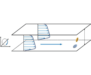
The dynamics of non-spherical tracer particles suspended in a spanwise-rotating turbulent channel flow is investigated by means of an Eulerian–Lagrangian approach. The inertialess tracer particles have no impact on the fluid flow since inertialess particles exert neither forces nor torques on the fluid. When a plane channel flow is subjected to spanwise rotation, the originally symmetric flow in the conventional non-rotating channel turns into an asymmetric flow field, as illustrated by the mean velocity profile in figure 1. The imposed system rotation gives also rise to rather different turbulence features on the pressure (unstable) and suction (stable) sides of the channel. The fundamental characteristics of rotating channel turbulence have been previously established by several investigations (Johnston et al. Reference Johnston, Halleent and Lezius1972; Kristoffersen & Andersson Reference Kristoffersen and Andersson1993; Lamballais et al. Reference Lamballais, Lesieur and Métais1996).
2.1. Rotating channel flow
The viscous fluid in the spanwise-rotating channel is assumed to be incompressible, Newtonian and isothermal. The mass continuity and the Navier–Stokes equations in non-dimensional form are as follows:
Here, ui represents the fluid velocity vector component in the xi direction, and p is the pressure fluctuation. The first term 1δ i1 on the right-hand side of (2.2) is the negative gradient of the effective mean pressure Peff, which includes the centrifugal acceleration, i.e. ${P_{eff}} = P-{\textstyle{1 \over 2}}\rho \varOmega _{system}^2{r^2}$, where r is the distance from the axis of rotation and $\rho$ is fluid density; see for instance the detailed derivations by Andersson (Reference Andersson2010). With the absorption of the centrifugal acceleration into Peff, the mathematically formulated problem becomes independent of the distance r from the axis of rotation, thereby leaving the last term in (2.2), i.e. the Coriolis force, as the only influence of the imposed channel rotation. Here, $\epsilon_{ijk}$ is Levi-Civita symbol.
The flow problem is governed by two non-dimensional parameters: Reτ = uτh/v represents the friction Reynolds number and $Ro = 2\varOmega_{system}h/u_{\tau}$ denotes the Rotation number, where $\varOmega_{system}$ is the angular velocity of the imposed system rotation, h represents channel half-width and v denotes the kinematic fluid viscosity. It should be emphasized that the Rotation number Ro is the reciprocal of the Rossby number conventionally used in geophysical fluid dynamics (Greenspan Reference Greenspan1968). The rotation number, as used herein, is a dimensionless measure of the relative importance of the system rotation and is routinely used in engineering fluid dynamics (e.g. Johnston et al. Reference Johnston, Halleent and Lezius1972; Kristoffersen & Andersson Reference Kristoffersen and Andersson1993; Lamballais et al. Reference Lamballais, Lesieur and Métais1996; Nakabayashi & Kitoh Reference Nakabayashi and Kitoh1996; Xia et al. Reference Xia, Shi and Chen2016). Contrary to the Rossby number, an increasing Rotation number Ro reflects a higher rate of system rotation.
In present work, the constant gradient of the mean effective pressure dPeff/d x is implemented in the x-component in (2.2) to propel the fluid flow through the channel. This driving force defines the global wall-shear velocity uτ as
where ρ is the constant density of the fluid.
The (x, y, z)-axes of the Cartesian coordinate system in figure 1 correspond to the streamwise, spanwise and wall-normal directions in the rotating channel, respectively. The corresponding velocity components in the rotating coordinate system are (u, v, w). The non-dimensional coordinates in (2.1) and (2.2) have been normalized by the geometric length scale h so that the wall-normal coordinate varies from −1 to +1. In the presentation of the results in § 3, however, we instead normalize the wall-normal coordinate by means of the viscous length scale v/uτ, such that z+ varies from −180 on the suction side to +180 on the pressure side.
2.2. Dynamics of tracer spheroidal particles
Spheroidal particles are typically characterized by three semi-axes, namely a, b and c, where c is the symmetry axis and a = b, and the shape of non-spheroid particles is commonly defined by the aspect ratio λ = c/a. In the pioneering work of (Zhang et al. Reference Zhang, Ahmadi, Fan and McLaughlin2001), the model for the motion of prolate particles (λ > 1) in wall turbulence has been presented in an overview. The model summarized the mathematical representation of the dynamics of particles and is employed in subsequent investigations (Challabotla et al. Reference Challabotla, Zhao and Andersson2015c; Jie et al. Reference Jie, Xu, Dawson, Andersson and Zhao2019a; Cui et al. Reference Cui, Huang, Xu, Andersson and Zhao2021; Cui & Zhao Reference Cui and Zhao2022). The analogous model has been applied to study non-spherical particles in this investigation. Two distinct Cartesian coordinate systems are employed by these researchers. The rotational motion of a particle is described in the particle frame xi = (x, y, z), with its origin at the mass centre of the particle and its axes oriented along the principal axes of the spheroid. The co-moving frame ${x^{\prime}_i} = (x^{\prime},y^{\prime},z^{\prime})$, which shares the same origin as the particle frame, has axes parallel to the channel frame.
Besides its shape, a solid particle is typically identified by a characteristic time scale τp, which measures the particle's response to changes in the local flow field. The particle exhibits a nearly instantaneous response to turbulent fluctuations if the relaxation time τp is significantly shorter than the Kolmogorov time scale τK of the turbulence. Such particles are unaffected by inertial forces such as drag and lift. They are commonly referred to as ‘tracers’ and passively migrate along with the fluid flow. Moreover, in cases such that the Stokes number St = τp/τK = 0, the torque exerted on the spheroids by the viscous fluid becomes negligible. However, the rotational motion of oblate and prolate tracer spheroids is different from that of the surrounding fluid, which is attributed to the particle shape and local fluid strain rate (Parsa et al. Reference Parsa, Calzavarini, Toschi and Voth2012; Zhao et al. Reference Zhao, Challabotla, Andersson and Variano2015). This phenomenon is exclusive to non-spherical particles (λ ≠ 1), which is the focus of the present investigation. While inertialess tracer particles travel passively along with the fluid flow, the angular dynamics of the particles is governed by the local fluid velocity-gradient tensor along their trajectories, following the Jeffery equation (Jeffery Reference Jeffery1922)
Here, the unit vector p represents the direction of the spheroid's symmetry axis c, whereas O and S denote rotation and strain-rate tensors of the fluid, respectively. Note that the rotation rate tensor O is related to the fluid rotation vector $\boldsymbol{\varOmega}$ according to ${O_{ij}} = {\varOmega _m}{\varepsilon _{mji}}$. Note the direction of fluid rotation is denoted as $\boldsymbol{\hat{\varOmega}}$.
2.3. Computational parameters and validation
In our investigation, the dynamics of inertia-free non-spherical particles with eleven different aspect ratios λ in spanwise-rotating turbulent channel flow at four different rotation numbers (Ro = 0, 1, 5, 10) is considered. Each aspect ratio configuration involves the simulation of $5\times10^5$ particles. The DNSs were performed with a computational domain of 12h × 6h × 2h using a total of 192 × 192 × 192 grid points in the streamwise (x), spanwise ( y) and wall-normal (z) directions, respectively. By integrating the equations of fluid motion ((2.1) and (2.2)) at Reτ = 180, the time-dependent three-dimensional turbulent flow field is acquired. The grid spacing Δz + in the wall-normal direction ranges from 0.9 to 2.86 and is refined towards both the walls, whereas the grid spacing in the two homogeneous directions is constant at Δx + = 11.3 and Δy + = 5.6. The time step is Δt + = 0.036. The DNS solver employed is similar to that utilized by Mortensen et al. (Reference Mortensen, Andersson, Gillissen and Boersma2008a) and Challabotla, Zhao & Andersson (Reference Challabotla, Zhao and Andersson2016). The homogeneous directions are treated using a pseudo-spectral method, while a second-order finite-difference discretization is implemented to handle the wall-normal direction. A second-order explicit Adams–Bashforth scheme is employed for advancing the time. In the x and y directions, periodic boundary conditions are applied, whereas no-slip boundary conditions are imposed at both walls. This set-up is similar to that applied by Yuan et al. (Reference Yuan, Andersson, Zhao, Challabotla and Deng2017).
Figure 2 shows results for different rotation numbers. The mean velocity profile U(z) and r.m.s. value r.m.s.(u′) of the velocity fluctuations in the flow direction are compared with DNS data reported by Xia et al. (Reference Xia, Shi and Chen2016). The spanwise rotation makes both the mean velocity profile U(z) and the r.m.s.(u′) distribution asymmetric about the channel centre at z = 0 with the highest turbulence level near the pressure side (to the left in these plots). These trends are consistent with early DNSs by Kristoffersen & Andersson (Reference Kristoffersen and Andersson1993) and Lamballais et al. (Reference Lamballais, Lesieur and Métais1996) at similar moderate rotation numbers. The almost perfect agreement with the data of Xia et al. (Reference Xia, Shi and Chen2016) at exactly the same Ro demonstrates the accuracy of both our methodology and the computational grids.
3. Results and discussion
Particle shape, parameterized by the aspect ratio λ, is known to have a significant influence on the orientational and rotational dynamics of non-spherical particles, as illustrated by the snapshots in figure 3 where 400 randomly sampled spheroids are shown (Challabotla et al. Reference Challabotla, Zhao and Andersson2015b,Reference Challabotla, Zhao and Anderssonc; Zhao et al. Reference Zhao, Challabotla, Andersson and Variano2015; Zhao & Andersson Reference Zhao and Andersson2016; Yuan et al. Reference Yuan, Andersson, Zhao, Challabotla and Deng2017; Yang et al. Reference Yang, Zhao and Andersson2018; Jie et al. Reference Jie, Zhao, Xu and Andersson2019b; Qiu et al. Reference Qiu, Marchioli, Andersson and Zhao2019; Cui et al. Reference Cui, Huang, Xu, Andersson and Zhao2021). The inertialess particles are seen to distribute themselves evenly throughout the rotating channel flow, similarly as in non-rotating channels (Challabotla et al. Reference Challabotla, Zhao and Andersson2015b,Reference Challabotla, Zhao and Anderssonc; Jie et al. Reference Jie, Xu, Dawson, Andersson and Zhao2019a,Reference Jie, Zhao, Xu and Anderssonb). The uniform dispersion of inertialess particles is, as expected, unaffected by the action of the Coriolis force due to the imposed system rotation. This is in contrast to the preferential concentration of inertial spheroids reported for instance by Challabotla et al. (Reference Challabotla, Zhao and Andersson2015b), Dotto & Marchioli (Reference Dotto and Marchioli2019).
Two major observations can readily be made from figure 3. First, the oblate spheroids exhibit a different orientation than the prolate spheroids. Second, the predominant particle orientations are more pronounced near the suction side at the lower wall (z+ = −180) than adjacent to the pressure side at the upper wall (z+ = +180). This asymmetric variation of the particle orientations is clearly an effect of the system rotation since the two channel halves are statistically equivalent in a non-rotating channel.
Many disk-like particles appear as circles in the plots in figure 3(a,b), especially in the centre region of the channel. This implies that these particles are oriented with their symmetry axis in the spanwise direction. These particles exhibit strong negative spanwise angular velocity, i.e. blueish ωy < 0, apparently driven by the negative mean vorticity dU/dz associated with the highly distorted mean velocity profile U(z) indicated in figure 1. Near the lower wall, several oblate spheroids appear as cigar shaped. This observation implies that these disk-like particles are seen from the side, i.e. they are oriented with their symmetry axis perpendicular to the wall. The prolate spheroids seem to be randomly oriented in the channel centre, but with a strong inclination towards parallel alignment with the wall on the suction side with their symmetry axis in the streamwise x-direction. These visually observed effects of the particle shape are most clearly seen for the flattest disks (λ = 0.1 in figure 3a) and the thinnest rods (λ = 10 in figure 3c). In the remainder of this section, the combined influence of particle shape and channel rotation will be delved into by means of statistical analysis.
3.1. Flow field
It is a well-established fact that the flow field in a plane channel subjected to spanwise system rotation is affected by the Coriolis force in a subtle way; see e.g. figure 2. The pioneering experimental investigation by Johnston et al. (Reference Johnston, Halleent and Lezius1972) and the computational study by Kristoffersen & Andersson (Reference Kristoffersen and Andersson1993) reported striking rotational effects on the velocity field, whereas Lamballais et al. (Reference Lamballais, Lesieur and Métais1996) for the first time demonstrated how system rotation affects the vorticity field. The majority of more recent studies, for instance, Nakabayashi & Kitoh (Reference Nakabayashi and Kitoh1996), Nakabayashi & Kitoh (Reference Nakabayashi and Kitoh2005), Grundestam et al. (Reference Grundestam, Wallin and Johansson2008), Visscher et al. (Reference Visscher, Andersson, Barri, Didelle, Viboud, Sous and Sommeria2011) and Xia et al. (Reference Xia, Shi and Chen2016), focused the attention on rotational alterations of the velocity field. For the sake of the present study, however, the effect of rotation on the vorticity field is of uttermost importance. We therefore first show how the level and anisotropy of the fluctuating vorticity vector are affected by Ro. Moreover, we also show how the instantaneous fluid rotation vector $\boldsymbol{\varOmega}$ is aligned with the three eigenvectors eLi of the left Cauchy–Green strain tensor. These alignments are essential for the exploration of how the spheroidal tracers align themselves in the simulated flow field. Let us recall that the flow statistics, to be presented in § 3.1.1, are unaffected by the presence of the inertialess particles.
3.1.1. Fluid vorticity
The three components of the fluctuating vorticity vector in the streamwise, spanwise and wall-normal directions are shown in figure 4 at four different rotation numbers. In the non-rotating case, figure 4(a) shows that the fluctuating vorticity is almost isotropic in the centre of the channel but exhibits a distinct anisotropy in the near-wall regions with the spanwise fluctuations exceeding the two other vorticity components; see also Andersson, Zhao & Variano (Reference Andersson, Zhao and Variano2015). The strict symmetry about the channel centre at Ro = 0 is broken by the system rotation. The vorticity fluctuations are slightly increased near the pressure side of the rotating channel and substantially reduced near the suction side. The enhancement and damping of the vorticity fluctuations near the pressure and suction sides, respectively, are most pronounced for the spanwise component, and the vorticity anisotropy has been substantially altered at the highest rotation rate Ro = 10 in figure 4(d). These rotation-induced changes in the vorticity field, which lead to an asymmetric variation across the channel, are consistent with the tendencies reported by Lamballais et al. (Reference Lamballais, Lesieur and Métais1996) and also imply that the rotation exerts a discernible impact on the vorticity fluctuations in the channel, especially in the flow direction and spanwise direction.
Figures 5 and 6 indicate that the alignment of the fluid rotation vector $\boldsymbol{\varOmega}$ relative to the three eigenvectors eLi of the left Cauchy–Green strain tensor evolves in time on the suction and pressure sides, respectively. Here, the rotation vector $\boldsymbol{\varOmega}$ is half of the fluid vorticity vector ω and the data were gained from a total time period ${t^ + } - t_0^ += 0\sim 180({t^ + } = t/(v/u_\tau ^2)$. In the non-rotating channel, i.e. Ro = 0, the fluid rotation vector gradually develops a modest alignment with the Lagrangian stretching direction, i.e. $\langle {({\boldsymbol{e}_{L1}} \bullet \boldsymbol{\hat{\varOmega}})^2}\rangle \approx 0.5$ as compared with 1/3 for random alignment. The alignment of $\boldsymbol{\varOmega}$ with eL 1 is in keeping with the results of Zhao & Andersson (Reference Zhao and Andersson2016). The reason why perfect preferential alignment of the vorticity with eL 1, i.e. $\langle {({\boldsymbol{e}_{L1}} \bullet \boldsymbol{\hat{\varOmega}})^2}\rangle = 1.0$, is not reached can be ascribed to a dynamic equilibrium between vorticity stretching and viscous effects, the latter which tends to separate the fluid rotation vector $\boldsymbol{\varOmega}$ from eL 1 (Ni et al. Reference Ni, Ouellette and Voth2014).
It is interesting to observe from figure 6 that the time evolution of the three correlations on the pressure side is practically unaffected by rotation. This is in striking contrast to the behaviour on the suction side. Although the results for Ro = 1 in figure 5(b) show a slower evolution in time than in the non-rotating channel, the asymptotic state closely resembles that for Ro = 0. At higher rotation rates Ro ≥ 5, however, the alignment of the rotation vector $\boldsymbol{\varOmega}$ with the eigenvector eL 1 is substantially reduced and $\langle {({\boldsymbol{e}_{L1}} \bullet \boldsymbol{\hat{\varOmega}})^2}\rangle \approx 0.30 < 1/3$. At Ro = 10, the fluid rotation is neither aligned with the stretching direction nor with the compression direction.
The rather different effects of system rotation on how the fluid rotation vector $\boldsymbol{\varOmega}$ aligns with the eigenvectors eLi are consistent with how the vorticity fluctuations are affected by Ro. As seen in the above figure 4 as well as in Lamballais et al. (Reference Lamballais, Lesieur and Métais1996), the system rotation has only a modest effect on the fluctuating vorticity on the pressure side, as compared with the substantial damping and accompanying alteration of the anisotropy on the suction side. Lamballais et al. (Reference Lamballais, Lesieur and Métais1996) examined the various terms in the transport equation for the vorticity fluctuations and concluded that the decreasing stretching term led to inhibition of the vortex stretching near the suction side. Their observation is therefore consistent with the increasing misalignment of the rotation vector $\boldsymbol{\varOmega}$ with eL 1 with higher rotation rates. In contrast, the almost negligible effect of channel rotation on the alignments $\langle {({\boldsymbol{e}_{Li}} \bullet \boldsymbol{\hat{\varOmega}})^2}\rangle$ in figure 6 is consistent with the modest influence of Ro on the vorticity fluctuations on the pressure side.
The surprising observation that the striking effects of system rotation on the alignments $\langle {({\boldsymbol{e}_{Li}} \bullet \boldsymbol{\hat{\varOmega}})^2}\rangle$ on the suction side in figure 5 are almost absent on the pressure side in figure 6 motivates further investigations. To this end, the variations of the alignments $\langle {({\boldsymbol{e}_{Li}} \bullet \boldsymbol{\hat{\varOmega}})^2}\rangle$ from the suction-side wall (z + = −180) to the pressure-side wall (z + = +180) are shown in figure 7. These data are obtained by averaging 5000 instantaneous alignments over a time period from ${t^ + } - t_0^ += 166$ to ${t^ + } - t_0^ += 174$ when the correlations have reached a statistically steady state; see figures 5 and 6. The statistics are computed in 200 different y-intervals and averaged over the homogenous x- and z-directions.
In the non-rotating channel, the fluid rotation vector $\boldsymbol{\varOmega}$ tends to preferentially align with the Lagrangian stretching eL 1 in the channel core. The alignment $\langle {({\boldsymbol{e}_{L1}} \bullet \boldsymbol{\hat{\varOmega}})^2}\rangle \approx 0.55$ is somewhat larger than the volume-averaged results in figures 5 and 6, but yet slightly lower than 0.60 as observed by Ni et al. (Reference Ni, Ouellette and Voth2014) in HIT. This preferential alignment is fully consistent with observations in the centre region of turbulent channel flow and Couette–Poiseuille flow reported by Zhao & Andersson (Reference Zhao and Andersson2016) and Yang et al. (Reference Yang, Zhao and Andersson2018), respectively. The distinct alignment of the rotation vector $\boldsymbol{\varOmega}$ with the Lagrangian stretching direction is gradually decreasing from |z +| ≈ 120 until a complete misalignment occurs at the two walls (|z +| = 180). At the two channel walls, $\boldsymbol{\varOmega}$ turns out to be aligned with eL 2, i.e. the rotation vector is perpendicular to both Lagrangian stretching and compression directions.
The alignments presented in figure 7(b–d) show how the fluid rotation vector behaves relative to the Lagrangian eigenvectors ei in a rotating channel. First of all, the alignments in the core region of the channel are almost unaffected by the imposed system rotation, despite that the mean velocity U(z) is severely distorted and exhibits a highly asymmetric profile, as shown in figure 2(a). Furthermore, the channel rotation has only a modest influence on the near-wall behaviour on the alignments near the pressure side of the rotating channel. This is consistent with the results presented in figure 6.
Near the suction-side wall, i.e. for z + < −120, the system rotation has a substantial influence on the alignments. The suction-side statistics accordingly become increasingly different from the corresponding pressure-side statistics and the resulting asymmetry between the two sides increases monotonically with Ro. The location at which a decrease of the alignment of $\boldsymbol{\varOmega}$ with eL 1 sets in shifts gradually away from the suction wall at z + = −180 with increasing Ro. Consequently, the fluid rotation vector $\boldsymbol{\varOmega}$ instead tends to align with eL 2 over a wider near-wall region. Nevertheless, despite the substantial effect of Ro on the suction side, the qualitative behaviour of the three different correlations $\langle {({\boldsymbol{e}_{Li}} \bullet \boldsymbol{\hat{\varOmega}})^2}\rangle$ remains the same as in the non-rotating case in figure 7(a).
The observation made from figure 7 that the effect of Ro is more pronounced on the suction side than on the pressure side of the rotating channel is consistent with the observed asymmetry of the vorticity fluctuations seen in figure 4. However, the vorticity fluctuations were not only damped near the suction side, but also the vorticity anisotropy was considerably altered with increasing Ro, as seen by their different trends in the near-wall region in figure 4(d). These qualitative differences in the vorticity field caused by the rotation are not reflected in the behaviour of the alignments in figure 7. This is probably because the velocity field in the immediate vicinity of the wall is dominated by a substantial mean vorticity in the spanwise direction, superimposed by gradually diminishing vorticity fluctuations as Ro increases. The dominance of the mean vorticity is probably why the three alignments behave similarly, despite the alterations of the anisotropy of the vorticity fluctuations. Moreover, the reduced turbulence level on the suction side, as seen in figure 2(b), gives more room for viscous influences. The increased misalignment on the suction side between the fluid rotation vector $\boldsymbol{\varOmega}$ and Lagrangian stretching eL 1 caused by rotation can be explained by the larger influence of viscosity, which alters the competition between viscous effects and vortex stretching.
3.1.2. The objectivity and frame independency
In this study, the alignment of vorticity with the eigenvectors of the Cauchy–Green strain tensor is computed along the particle trajectory, which is the same as the fluid trajectory because of the inertia-free assumption of particles in the current work. Meanwhile, the orientation of spheroidal particles is governed by the fluid velocity-gradient tensor along the trajectory. Although the turbulent flows are computed in a non-inertial frame fixed in the rotating channel, the particles passively follow the fluid particles. Therefore, it is not surprising that the alignment between vorticity (and also the particle orientation) and the Lagrangian stretching directions is unaffected by system rotation even though the velocity profile changes, namely these results are the same whether they are in the inertial or non-inertial frame. This invariance in even non-inertial frames was one of the main reasons why the Cauchy–Green eigenvectors and other concepts of Lagrangian coherent structures (LCSs) were introduced into fluid mechanics by Haller (Reference Haller2015). The present case represents a striking example of the objectivity and frame independency of Lagrangian dynamics with respect to particle orientations.
3.2. Orientation
How non-spherical particles orient themselves in turbulent flows is traditionally referred to an inertial reference system since any preferred orientations might be of practical interest (see, e.g. Voth & Soldati Reference Voth and Soldati2017). In the present study, we have considered five different oblate spheroids (λ = 0.05, 0.1, 0.2, 0.333 and 0.5) and five different prolate spheroids (λ = 20, 10, 5, 3 and 2) and spheres (λ = 1). We first refer particle orientations in § 3.2.1 to a non-inertial reference system fixed to the rotating channel; see figure 1. Next, in order to understand the underlying physics, the particle orientations will also be referred to the Lagrangian directions of fluid compression and extension in § 3.2.2.
3.2.1. Orientation in the channel reference frame
Figure 8 shows the variation of the mean values of the absolute direction cosines for oblate and prolate particles on the suction side (−180 < z + < 0) and on the pressure side (0 < z + < 180) in the non-rotating channel Ro = 0 for which the two channel halves are statistically identical. Here, the direction cosine cosθi is defined by the angle θi between the symmetry axis of the prolate or oblate spheroid, i.e. the z-direction in the particle frame, and the xi-direction of the channel frame. The mean value of the absolute cosine $\langle |\cos {\theta _i}|\rangle$ thus becomes a measure of the particle orientation relative to the channel.
The mean value of the absolute direction cosine approaches unity in the flow direction for prolate spheroids and in the wall-normal direction for oblate spheroids near the two channel walls. This reflects the preferential near-wall orientation of long rods and thin disks. On the contrary, the mean values of the absolute direction cosines in all three directions and for rods and disks tend to 0.5 in the channel centre, thus reflecting an isotropic orientation of prolate and oblate particles associated with the almost isotropic vorticity field seen in figure 4(a); see also Andersson et al. (Reference Andersson, Zhao and Variano2015). The tendency of the inertialess spheroids to preferentially orient near the walls is clearly shape-dependent and most pronounced for the longest rod-like spheroids (λ = 20) and the flattest disk-like spheroids (λ = 0.05). All these results are similar to earlier numerical results (Mortensen et al. Reference Mortensen, Andersson, Gillissen and Boersma2008b; Challabotla et al. Reference Challabotla, Zhao and Andersson2015b,Reference Challabotla, Zhao and Anderssonc) from non-rotating channel flow simulations of tracer spheroids and the tendency is analogous to experimental findings with regard to fibres with no rotation (Shaik & van Hout Reference Shaik and van Hout2023).
To explore the effect of channel rotation on the spheroids’ preferential orientations, the mean values of the particles’ absolute direction cosine for Ro = 1, 5 and 10 are presented in figures 9–11, respectively. At the lowest rate of spanwise rotation Ro = 1 the results in figure 9 are almost indistinguishable from the corresponding results for the non-rotating channel in figure 8. The observation that low system rotation has only negligible influence on the preferential particle orientations is probably caused by the observations made in § 3.1.1, namely that rotation Ro = 1 has only a modest quantitative effect on the vorticity field and the vorticity anisotropy still remains qualitatively the same on the pressure and suction sides of the rotating channel.
At faster rotation Ro = 5 and 10, the orientation statistics in figures 10 and 11 show that the two channel halves respond differently to the imposed rotation. Nevertheless, the absolute cosines $\langle |\cos {\theta _i}|\rangle$ near the pressure-side wall at z + = +180 are surprisingly unaffected by rotation even for Ro = 10 so that prolate spheroids orient preferentially in the streamwise direction whereas oblate spheroids orient their symmetry axis in the wall-normal direction. Despite the substantial alterations in the fluctuating vorticity field seen in figure 4 (c,d), the alignments of the vorticity vector with the Lagrangian stretching and compression directions are practically unaffected by rotation (see figure 6). This suggests that the preferential particle orientations are governed by how the vorticity vector is oriented relative to the Lagrangian unit vectors. The almost isotropic orientation of prolate and oblate spheroids in the channel centre is maintained at all rotation numbers, despite the substantial alterations of the mean velocity distribution and the turbulent velocity fluctuations seen in figure 2.
On the suction side of the channel, however, the absolute cosines $\langle |\cos {\theta _i}|\rangle$ presented to the left in figures 10 and 11 for Ro = 5 and 10 are rather different from the corresponding results shown in figures 8 and 9 for Ro = 0 and 1. Since the orientational statistics are almost unaffected by rotation on the pressure side of the rotating channel, the strong rotational effect on the suction side leads to a highly asymmetric variation across the rotating channel. Nevertheless, the tendencies of the longest rod-like particles (λ = 20) and the flattest disk-like particles (λ = 0.05) to orient themselves in the streamwise and wall-normal directions, respectively, are maintained also at high rotation rates. However, while this strong preferential orientation decayed rapidly with the distance from the wall in the non-rotating channel, the preferred alignment persists over the much wider range −180 < z + < −100 for Ro = 10. It is particularly noteworthy that, although the vorticity fluctuations are substantially damped next to the suction-side wall, the tendency of the particles to orient preferentially is maintained also at Ro = 0 and even extends farther away from the wall. The observed effects of Ro on the suction side of the rotating channel can therefore not be ascribed to the Eulerian statistics in figure 4. However, the statistics in figure 7 show that the characteristic near-wall alignments of the fluid vorticity vector $\varOmega$ with the Lagrangian eigenvectors eLi of the left Cauchy–Green strain tensor extend much further away from the suction-side wall at Ro = 5 and 10 than on the almost unaffected pressure-side wall.
From the preceding results in figures 8–11, we have learned that the preferential near-wall orientations of prolate and oblate spheroids in the streamwise and wall-normal directions, respectively, as well as the isotropic orientation in the core region, are retained also when the channel is subjected to spanwise rotation. The preferential orientations are also most pronounced for the most aspherical particles. The only noteworthy effect of rotation is that the preferential particle orientation extends much further away from the wall on the suction side of the rapidly rotating channel. These findings can readily be explained by the observed effects of Ro on the Lagrangian correlations $\langle {({\boldsymbol{e}_{Li}} \bullet \boldsymbol{\hat{\varOmega}})^2}\rangle$.
3.2.2. Alignment correlations of spheroidal particles
Let us first recall that, according to (2.4), the rate of change of the particle orientation responds immediately to the local flow field (and to how the particle is oriented locally in the field). However, the particle orientation itself does not respond spontaneously to changes in the local flow field, but rather aligns gradually with the Lagrangian stretching and compression directions (similarly as the vorticity vector does in figures 5 and 6)
Finally, to elucidate the underlying mechanisms governing the subtle orientations of inertialess spheroids in rotating channel flow turbulence seen in figures 8–11, the variances of the alignment of the orientation vector p of rods and disks relative to the three eigenvectors eLi of the left Cauchy–Green strain tensor are shown from wall to wall in figure 12 for the four different rotation numbers Ro = 0, 1, 5, 10. The statistics in figure 12 are obtained by averaging 12 000 Lagrangian particle trajectories in the same statistically steady state from ${t^ + } - t_0^ += 166$ to ${t^ + } - t_0^ += 174$ as used for the alignment statistics shown in figure 7.
In the non-rotating channel, all alignment statistics in figure 12(a) exhibit the expected symmetry across the channel. The longest fibre-like spheroids (λ = 20) and the flattest disk-like spheroids (λ = 0.05) are almost perfectly aligned with the Lagrangian stretching direction eL 1 and the Lagrangian compression direction eL 3, respectively. This strong alignment of elongated spheroids with eL 1 reduces with lower aspect ratio, but even the λ = 2 particles exhibit a similar degree of alignment with eL 1 as the fluid vorticity vector $\boldsymbol{\varOmega}$ in figure 7(a). The tendency for oblate spheroids to align with eL 3 is similarly reduced as the aspect ratio λ increases from 0.05 to 0.5. The distinct alignments of the most aspherical particles with the Lagrangian eigenvectors persist over approximately 80 % of the channel cross-section, but gradually reduce in the vicinity of the channel walls. These results for Ro = 0 are consistent with the observations made by Zhao & Andersson (Reference Zhao and Andersson2016). In the present context, however, it is noteworthy that these alignments are essentially unaffected by the imposition of a modest rate of channel rotation, i.e. Ro = 1, as seen in figure 12(b). Although the Coriolis force associated with the imposed system rotation affects the vorticity field differently on the suction and pressure sides (see figure 4b), the particle alignment statistics in figure 12(b) remain essentially unaffected by rotation.
Even at higher rotation numbers Ro = 5 and 10 shown in figure 12(c,d), the alignments between the particle orientation vector p of long rods and flat disks and the Lagrangian stretching and compression directions remain almost the same as in the non-rotating case in the core region of the channel. Even the substantial reduction of these alignments in the near-wall region is nearly unaffected by rotation on the pressure side of the channel. Near the suction side, however, two noteworthy distinctions can be observed. First, the characteristic core-region alignments of rod-like and disk-like particles with eL 1 and eL 3, respectively, start to decay much further away from the suction-side wall than for Ro = 0. The decay of the alignments takes place over roughly twice as thick a zone than in the non-rotating channel. Second, these alignments reach a local minimum, i.e. maximum de-alignment, approximately 20 wall units v/uτ away from the suction-side wall.
Although the general trend of the wall-to-wall variation is similar to what was found by Cui et al. (Reference Cui, Dubey, Zhao and Mehlig2020), namely that the alignment of elongated rods with the direction of Lagrangian stretching is stronger near the channel centre than in the vicinity of the channel walls, the slender rods and flatter disks deviate more from the Lagrangian stretching and compression directions, respectively, near the suction-side wall in the rapidly rotating channel. The observed maximum de-alignment approximately 20v/uτ away from the suction wall can be considered as an effect of system rotation since such local minima were not observed in a non-rotating channel by Cui et al. (Reference Cui, Dubey, Zhao and Mehlig2020).
The observations made from figure 12 cannot be explained in terms of the rotation-induced effects of system rotation on the velocity field, as shown in figure 2 and greater detail by Johnston et al. (Reference Johnston, Halleent and Lezius1972), Kristoffersen & Andersson (Reference Kristoffersen and Andersson1993) and Lamballais et al. (Reference Lamballais, Lesieur and Métais1996). The significant distortion of the mean velocity profile in figure 2(a) leads to a 50 % reduction (increase) of the wall shear stress on the suction (pressure) side of the rotating channel, accompanied by a decrease (increase) of the velocity fluctuations (figure 2b) and the vorticity fluctuations (figure 4) on the suction (pressure) side.
4. Conclusions
The orientation dynamics of non-spherical tracer particles in wall-bounded turbulence have been explored in detail by Zhao & Andersson (Reference Zhao and Andersson2016) for non-rotating channel flow. To investigate the effect of channel rotation on spheroids’ orientation and uncover the underlying physical mechanisms, the orientation dynamics of disk-like (λ < 1) and fibre-like (λ > 1) tracer particles suspended in turbulent channel flow subjected to spanwise rotation at four different rotations Ro = 0, 1, 5, 10 has been investigated. The turbulent flow field is acquired by DNSs, in which rotation is achieved by means of a Coriolis force implemented in the governing Navier–Stokes equations. Spheroidal inertialess particles are tracked by a Lagrangian point-particle method and altogether eleven different particle shapes were considered with aspect ratios ranging from 0.05 to 20, i.e. from fairly flat disk-like particles via spheres (λ = 1) to long rod-like particles.
The imposed channel rotation gave rise to the so-called pressure and suction sides of the channel, referring to the wall-normal pressure gradient set up to balance the Coriolis force. The turbulent flow field exhibits increasingly asymmetric variations across the channel, with augmented and damped vorticity fluctuations on the pressure and suction sides, respectively, consistent with the earlier results of (Lamballais et al. Reference Lamballais, Lesieur and Métais1996) for an unladen channel flow. Moreover, the amount of alignment of the fluid rotation vector $\boldsymbol{\varOmega}$ with the maximum stretching eigenvector eL 1 of the left Cauchy–Green tensor has proved to be a useful tool in the analysis of how non-spherical particles orient themselves in HIT (Ni et al. Reference Ni, Ouellette and Voth2014) and turbulent channel flows (Zhao & Andersson Reference Zhao and Andersson2016). Now we found that $\boldsymbol{\varOmega}$ aligned with the Lagrangian stretching direction eL 1 over the core region of the channel but tended to be perpendicular to eL 1 in the proximity of both walls for weak rotation Ro = 1, almost indistinguishable from the results for the non-rotating channel. At the higher rotation rates Ro ≥ 5, the alignment statistics remained nearly unaffected by the system rotation in the core region and all the way to the pressure-side wall. Near the suction side of the channel, however, the gradually decreasing alignment between $\boldsymbol{\varOmega}$ and eL 1 commences significantly further from the wall, typically 80 wall units $v/u_{\tau}$ away. This new finding is attributed to the rotation-induced damping of the enstrophy and the accompanying relative augmentation of viscous effects, thereby facilitating the separation between $\boldsymbol{\varOmega}$ and eL 1.
Although inertialess spheroids translate along with the fluid flow independently of particle shape, the particles exhibit shape-dependent orientations in the near-wall regions whereas the particles orient almost isotopically in the core region of the channel. Prolate and oblate spheroids tend to orient along and perpendicular to the streamwise x-direction in the near-wall region and these preferential alignments amplify with increasing asphericity, in accordance with Zhao & Andersson (Reference Zhao and Andersson2016). This behaviour is observed also in the slowly rotating channel and the only observable difference at Ro = 1 is that the particles’ re-orientation sets in somewhat further away from the suction-side wall than in the non-rotating channel. At higher rotation rates, i.e. Ro ≥ 5, the changeover from the isotropic core-region mode to the near-wall mode commences even further away from the wall. Thus, despite the very minor effect of rotation near the pressure-side wall, the distinct Ro-dependency on the suction side makes the wall-to-wall variation of the directional cosines highly asymmetric.
The preferential orientations of inertialess spheroids in the non-rotating channel were proved by Zhao & Andersson (Reference Zhao and Andersson2016) to be linked to the directions of Lagrangian stretching and compression, i.e. rod-like particles were aligned with the direction of strongest Lagrangian stretching eL 1 and disk-like particles were oriented along the direction of Lagrangian compression eL 3. Moreover, the strongest alignment of elongated rods with eL 1 is found in the core region of the channel (Cui et al. (Reference Cui, Dubey, Zhao and Mehlig2020). Although the imposed rotation has a major influence on the velocity and vorticity fields, as described in detail by Kristoffersen & Andersson (Reference Kristoffersen and Andersson1993) and Lamballais et al. (Reference Lamballais, Lesieur and Métais1996), the tendencies of prolate and oblate spheroids to align with eL 1 and eL 3, respectively, are mostly unaffected by the imposition of system rotation.
The only noteworthy influence of Ro on the particle alignments is seen near the suction side of the rotating channel where the near-wall mode of orientation extends considerably further away from the suction-side wall than in the non-rotating channel. This extension of the transition zone between near-wall mode and core-region mode orientation is apparently a result of the rotation-induced damping of the vorticity fluctuations (turbulent enstrophy) caused by the presence of the Coriolis force. Moreover, while maximum de-alignment between the spheroids and the Lagrangian eigenvectors occurred at the walls of the non-rotating channel, the lowest alignments were seen approximately $20v/u_{\tau}$ away from the suction wall for Ro = 10.
Besides the near-wall effects on particle orientations, we have found that inertialess spheroids align with the Lagrangian eigenvectors eL 1 and eL 3, just as in non-rotating channel flow (Zhao & Andersson Reference Zhao and Andersson2016) and in HIT (Ni et al. Reference Ni, Ouellette and Voth2014). The present findings manifest that this universal principle also applies to rotating, i.e. non-inertial, reference systems.
How particles orient in a rotating turbulent field has been studied in a channel flow configuration. The orientation of a non-spherical particle relative to the local fluid vorticity determines the particle's rotational motion (Yang et al. Reference Yang, Zhao and Andersson2018; Zhao et al. Reference Zhao, Challabotla, Andersson and Variano2019). Rods spin if aligned with the vorticity vector and tumble if oriented perpendicular to the fluid vorticity vector. The present findings are therefore relevant also for how particles rotate in flow fields subjected to a Coriolis force.
Funding
This work is supported by the National Natural Science Foundation of China (grant nos. 52306203, 92252104, 12388101, 12302285), the Shaanxi Province QCY Innovative and Entrepreneurial Talent Programme (grant no. QCYRCXM-2022-134), the China Postdoctoral Science Foundation (grant no. 2022M721849).
Declaration of interests
The authors report no conflict of interest.