Hostname: page-component-cd9895bd7-gvvz8 Total loading time: 0 Render date: 2024-12-26T18:33:21.761Z Has data issue: false hasContentIssue false

Characterization of energy transfer and triadic interactions of coherent structures in turbulent wakes

Published online by Cambridge University Press:  12 September 2023
Dinesh Kumar Kinjangi
Affiliation:
Department of Mechanical Engineering, University of Memphis, Memphis, TN 38152, USA
Daniel Foti*
Affiliation:
Department of Mechanical Engineering, University of Memphis, Memphis, TN 38152, USA
*
Email address for correspondence: [email protected]

Abstract

Turbulent wakes are often characterized by dominant coherent structures over disparate scales. Dynamics of their behaviour can be attributed to interscale energy dynamics and triadic interactions. We develop a methodology to quantify the dynamics of kinetic energy of specific scales. Coherent motions are characterized by the triple decomposition and used to define mean, coherent and random velocity. Specific scales of coherent structures are identified through dynamic mode decomposition, whereby the total coherent velocity is separated into a set of velocities classified by frequency. The coherent kinetic energy of a specific scale is defined by a frequency triad of scale-specific velocities. Equations for the balance of scale-specific coherent kinetic energy are derived to interpret interscale dynamics. The methodology is demonstrated on three wake flows: (i) ${Re}=175$ flow over a cylinder; (ii) a direct numerical simulation of ${Re}=3900$ flow over a cylinder; and (iii) a large-eddy simulation of a utility-scale wind turbine. The cylinder wake cases show that energy transfer starts with vortex shedding and redistributes energy through resonance of higher harmonics. The scale-specific coherent kinetic energy balance quantifies the distribution of transport and transfer among coherent, mean and random scales. The coherent kinetic energy in the rotor scales and the hub vortex scale in the wind turbine interact to produce new scales. The analysis reveals that vortices at the blade root interact with the hub vortex formed behind the nacelle, which has implications for the proliferation of scales in the downwind near wake.

JFM classification

Type
JFM Papers
Copyright
© The Author(s), 2023. Published by Cambridge University Press

1. Introduction

While turbulent flows are characterized by a broad range of scales that often appear chaotic with random fluid motions, persistent, organized coherent structures are often observed (Brown & Roshko Reference Brown and Roshko1974; Hussain & Zaman Reference Hussain and Zaman1985). The dynamics of these so-called coherent structures play an important role in turbulent flow behaviour (Cantwell Reference Cantwell1981; Hussain Reference Hussain1983; Haller Reference Haller2015). Multiple scales of coherent structures within any particular flow can exist due to different origins, disparate characteristic scales, spatio-temporal developments depending on the Reynolds number and other pertinent parameters in the flow. Furthermore, they are often the dominant flow features and appear in many flows, including wall-bounded flows (Guala, Hommema & Adrian Reference Guala, Hommema and Adrian2006; Hutchins & Marusic Reference Hutchins and Marusic2007; Jiménez Reference Jiménez2018), jets (Hussain & Zaman Reference Hussain and Zaman1985; Zaman Reference Zaman1996; Schmidt et al. Reference Schmidt, Towne, Colonius, Cavalieri, Jordan and Brès2017; Towne, Schmidt & Colonius Reference Towne, Schmidt and Colonius2018) and wakes (Wygnanski, Champagne & Marasli Reference Wygnanski, Champagne and Marasli1986; Sohankar, Norberg & Davidson Reference Sohankar, Norberg and Davidson1999; Foti et al. Reference Foti, Yang, Guala and Sotiropoulos2016; Yang et al. Reference Yang, Hong, Barone and Sotiropoulos2016; Bai & Alam Reference Bai and Alam2018). However, even if they share common traits, the interactions of coherent structures among themselves or the surrounding flow, as well as other associated dynamics and mechanisms such as genesis, instabilities and breakdown, remain unclear. The objective of this work is to develop a framework and analyses to elucidate the mechanisms of the interactions of coherent structures and other scales in the flow.

The transfer of kinetic energy among scales, or interscale energy dynamics, can be leveraged to identify the formation, evolution and destruction of coherent structures. Multi-scale turbulence energy transfer has a long history based on the seminal Richardson–Kolmogorov theory (Richardson Reference Richardson1922; Kolmogorov Reference Kolmogorov1941) of the turbulent energy cascade. The energy cascade postulates that at sufficiently large Reynolds numbers, the energy transfers from the largest energy-containing scales to the smallest universal scales. This is a consequence of the quadratic nonlinearity present in the Navier–Stokes equations, which gives rise to triadic interactions whereby a triplet of wavenumber or frequency scales sum to zero (i.e. $\boldsymbol {\kappa }^i \pm \boldsymbol {\kappa }^j \pm \boldsymbol {\kappa }^k = 0$ or $f^i \pm f^j \pm f^k = 0$). Pioneered by Kraichnan (Reference Kraichnan1967) and Kraichnan (Reference Kraichnan1971), the role of triadic interactions in turbulence has been subject to a number of investigations (Domaradzki & Rogallo Reference Domaradzki and Rogallo1990; Brasseur & Wei Reference Brasseur and Wei1994; Waleffe Reference Waleffe1997). It has been shown that the largest scales can impact the small scale velocity statistics (Mininni, Alexakis & Pouquet Reference Mininni, Alexakis and Pouquet2006) and that the nonlinearity imposes significant complexity by promoting nonlocal interactions (Brasseur & Wei Reference Brasseur and Wei1994; Domaradzki et al. Reference Domaradzki, Liu, Härtel and Kleiser1994) and extreme dissipation events (Zhou et al. Reference Zhou, Nagata, Sakai and Watanabe2019; Farazmand & Sapsis Reference Farazmand and Sapsis2017).

Energy transfer between the mean and fluctuating parts of the flow has been studied in great detail in a variety of flows (Cal et al. Reference Cal, Lebrón, Castillo, Kang and Meneveau2010; Calaf, Meneveau & Meyers Reference Calaf, Meneveau and Meyers2010; Yang et al. Reference Yang, Howard, Guala and Sotiropoulos2015; Cimarelli et al. Reference Cimarelli, De Angelis, Jimenez and Casciola2016; Gatti et al. Reference Gatti, Cimarelli, Hasegawa, Frohnapfel and Quadrio2018; Symon, Illingworth & Marusic Reference Symon, Illingworth and Marusic2021). Energy transfer plays a key role in the organization of multi-scale coherent structures and turbulent eddies, and insight into their self-sustaining mechanisms (Kravchenko, Choi & Moin Reference Kravchenko, Choi and Moin1993; Hamilton, Kim & Waleffe Reference Hamilton, Kim and Waleffe1995; Waleffe Reference Waleffe1997). While energy transfer between the mean and the fluctuating part (i.e. turbulence production) can provide insights into high-Reynolds-number flows (Calaf et al. Reference Calaf, Meneveau and Meyers2010; Cal et al. Reference Cal, Lebrón, Castillo, Kang and Meneveau2010; Yang et al. Reference Yang, Howard, Guala and Sotiropoulos2015; Gatti et al. Reference Gatti, Cimarelli, Hasegawa, Frohnapfel and Quadrio2018; Symon et al. Reference Symon, Illingworth and Marusic2021), the multi-scale physics leads to anisotropy (Cimarelli et al. Reference Cimarelli, De Angelis, Jimenez and Casciola2016), intermittency (Piomelli et al. Reference Piomelli, Cabot, Moin and Lee1991; Domaradzki, Liu & Brachet Reference Domaradzki, Liu and Brachet1993; Cerutti & Meneveau Reference Cerutti and Meneveau1998; Dubrulle Reference Dubrulle2019), inhomogeneous spatial fluxes (Cimarelli et al. Reference Cimarelli, De Angelis, Jimenez and Casciola2016) and nonlinear redistribution of energy that is strongly scale- and position-dependent (Piomelli, Yu & Adrian Reference Piomelli, Yu and Adrian1996; Hong et al. Reference Hong, Katz, Meneveau and Schultz2012). However, quantification of turbulence production alone cannot assess these turbulence characteristics, and interscale dynamics can be complicated by inverse cascade and energy redistribution (Alexakis & Biferale Reference Alexakis and Biferale2018; Carbone & Bragg Reference Carbone and Bragg2020).

To capture the interscale dynamics of coherent structures, the spatio-temporal fluctuations associated with coherent structures need to be identified and separated from the total fluctuations (Reynolds & Hussain Reference Reynolds and Hussain1972). A commonly employed technique to quantify the turbulent fluctuations that are associated with coherent structures is the triple decomposition of the velocity (Hussain & Reynolds Reference Hussain and Reynolds1970), but it requires additional insights and operators to distinguish coherent quantities. The triple decomposition of the velocity leads to three coupled equations that capture the evolution of kinetic energy: (i) the mean kinetic energy equation; (ii) the coherent kinetic energy equation associated only with the coherent fluctuations; and (iii) the random kinetic energy equation. The three equations have been used to identify the exchange of energy between the mean, coherent and random scales. In particular, the coherent kinetic energy equation has been applied to scale-by-scale energy analysis (Thiesset et al. Reference Thiesset, Danaila, A Antonia and Zhou2011), controls of coherent structures (Chen, Yao & Hussain Reference Chen, Yao and Hussain2021) and analysis of interscale transfer (Reynolds & Hussain Reference Reynolds and Hussain1972; Thiesset, Danaila & Antonia Reference Thiesset, Danaila and Antonia2014; Chan, Schlatter & Chin Reference Chan, Schlatter and Chin2021), but they only consider the scale of one coherent motion. Further insight is needed to identify multiple, specific scales and account for a scale-specific coherent kinetic energy.

A precise definition of a coherent structure has never been fully established due to disparate features observed ranging from strong vortical structures such as tip vortices to large meandering features in turbulent boundary layers and wakes. This may be partly why many techniques have been proposed to identify coherent structures. Methods include Eulerian diagnostics (Hunt, Wray & Moin Reference Hunt, Wray and Moin1988; Jeong & Hussain Reference Jeong and Hussain1995; Dubief & Delcayre Reference Dubief and Delcayre2000), which threshold on various kinematic metrics. Temporal filtering methods (Hussain Reference Hussain1986) have commonly been employed to identify a single coherent structure with a regular Strouhal number; however, coarse-graining (Motoori & Goto Reference Motoori and Goto2019; Dong et al. Reference Dong, Huang, Yuan and Lozano-Durán2020) and Lagrangian methods (Chrisohoides & Sotiropoulos Reference Chrisohoides and Sotiropoulos2003; Haller Reference Haller2015) can also be employed. However, these aforementioned techniques almost always quantify a single coherent fluctuation as part of the triple decomposition. These methods can be much more cumbersome to employ where multiple coherent structures with different scales are present in the flow. Building on a general definition of a coherent structure that it is region of the flow over which a flow variable exhibits high spatio-temporal correlation with itself or another (Robinson Reference Robinson1991), we pursue a methodology that allows multiple coherent structures to be represented with dynamical properties through mode decomposition (Sirovich Reference Sirovich1987; Holmes et al. Reference Holmes, Lumley, Berkooz and Rowley2012; Mezić Reference Mezić2013). The method leverages large quantities of data with a high spatio-temporal resolution that have become ubiquitous in flow solutions and is restricted to statistically stationary flows. Mode decomposition provides a method for analysis and data reduction where the flow variable is decomposed into a sum of parts each defined by the tuple of amplitude, temporal coefficient and spatial mode. When mode decompositions are paired with compressive sensing (Donoho Reference Donoho2006; Fowler Reference Fowler2009), the objective reduction of the number of parts can be undertaken (Kutz Reference Kutz2013; Jovanović, Schmid & Nichols Reference Jovanović, Schmid and Nichols2014). A common mode decomposition is proper orthogonal decomposition (POD), which is the decomposition of the velocity covariance matrix and produces orthogonal modes that optimally represent the variance of the data (Sirovich Reference Sirovich1987). Due to the orthogonality of the modes and ordered mode amplitude, this is commonly employed for analysis (Berkooz, Holmes & Lumley Reference Berkooz, Holmes and Lumley1993; VerHulst & Meneveau Reference VerHulst and Meneveau2015; Foti, Giorno & Duraisamy Reference Foti, Giorno and Duraisamy2020) and reduced-order modelling (Rowley, Colonius & Murray Reference Rowley, Colonius and Murray2004; Holmes et al. Reference Holmes, Lumley, Berkooz and Rowley2012). However, spectral mode decompositions such as dynamic mode decomposition (Schmid Reference Schmid2010), spectral POD (Towne et al. Reference Towne, Schmidt and Colonius2018) and Koopman mode decomposition (Mezić Reference Mezić2013) are eigendecompositions of an operator that organizes modes based on their spectral characteristics (Rowley et al. Reference Rowley, Mezic, Bagheri, Schlatter and Henningson2009; Schmid Reference Schmid2010). There are several benefits of employing these methods to identify coherent structures for interscale energy dynamics that will be shown: (i) modes are identified by a unique frequency scale which is directly associated with a specific coherent quantity; (ii) support of the mode remains in physical space rather than spectral space; (iii) coherent kinetic energy at specific frequency scales can be identified; (iv) multiple and disparate scales are individually identified; and (v) triadic interactions can be directly elucidated in the scale-specific coherent kinetic energy balance derived herein.

Coherent structures have been shown to transfer energy to a range of scales (Goto, Saito & Kawahara Reference Goto, Saito and Kawahara2017; Motoori & Goto Reference Motoori and Goto2019). The scale-by-scale energy balances, such as the Kármán–Howarth–Monin equation and its generalizations (Hill Reference Hill2002; Gatti et al. Reference Gatti, Chiarini, Cimarelli and Quadrio2020), have been used to assess the spatial correlations and interscale dynamics in specific areas of a large sub-set of flows (Gomes-Fernandes, Ganapathisubramani & Vassilicos Reference Gomes-Fernandes, Ganapathisubramani and Vassilicos2015; Valente & Vassilicos Reference Valente and Vassilicos2015; Portela, Papadakis & Vassilicos Reference Portela, Papadakis and Vassilicos2017; Zhou et al. Reference Zhou, Nagata, Sakai, Watanabe, Ito and Hayase2020). These analyses focus on the structure function and associated length scales in the flow. While originally formulated in traditional Reynolds decomposition, other derivations have employed the triple decomposition to identify a coherent scale (Thiesset et al. Reference Thiesset, Danaila, A Antonia and Zhou2011, Reference Thiesset, Danaila and Antonia2014). Other analyses have focused on using the resolvent (McKeon & Sharma Reference McKeon and Sharma2010); however, the nonlinear mechanisms preclude the employment of linear models to predict nonlinear energy transfer (Jin, Symon & Illingworth Reference Jin, Symon and Illingworth2021; Symon et al. Reference Symon, Illingworth and Marusic2021). The bispectrum, a signal processing of time series with third-order spectra, can detect quadratic phase coupling. The bispectrum, similar to the power spectrum, has also been used to identify triadic interaction and energy transfer in atmospheric boundary layers (Lii, Rosenblatt & Van Atta Reference Lii, Rosenblatt and Van Atta1976) and jets (Corke, Shakib & Nagib Reference Corke, Shakib and Nagib1991; Gee et al. Reference Gee, Atchley, Falco, Shepherd, Ukeiley, Jansen and Seiner2010). Classic bispectrum signal processing analysis is capable of detecting quadratic nonlinearity in a one-dimensional signal. Recently, a bispectral mode decomposition was developed by Schmidt (Reference Schmidt2020) to identify triadic relationships that represent the dynamics of the structure based on third-order statistics of spatio-temporal data. Similar to the present work, Baj & Buxton (Reference Baj and Buxton2017) used triple decomposition with a spectral mode decomposition to derive energy balances. It has been applied to flows over a cylinder (Biswas, Cicolin & Buxton Reference Biswas, Cicolin and Buxton2022) and fractal turbulence generation (Baj & Buxton Reference Baj and Buxton2017). However, the analysis does not generalize the identification of triads within the framework.

The present work develops a framework to quantify interscale dynamics of coherent structures through kinetic energy budgets with explicitly imposing triadic interactions. While the range of scales is large and pertinent at very large Reynolds numbers, in this work, we focus on three cases of varying Reynolds number and complexity. We are motivated by considering: (i) that the interaction between the most dominant coherent structures is not fully understood; (ii) triadic interactions occur over all scales; and (iii) wake-like flows exhibit strong coherence of specific scales, which are easy to identify and validate. In what follows, we will develop a set of equations for the scale-specific coherent kinetic energy balance based on identifying prominent modes that are associated with coherent structures. Section 2 formulates and describes the scale-specific coherent kinetic energy balance methodology. Compressive sensing is included to identify prominent scales for analysis. Section 3 discusses the numerical methods employed for computational simulation. Section 4 details analysis of three wake-like flows from low-Reynolds-number flow over a cylinder to a utility-scale wind turbine and § 5 provides final conclusions and discussion.

2. Methodology

The incompressible Navier–Stokes equations are the following ($i,j = 1,2,3$ and repeated indices imply summation):

(2.1)$$\begin{gather} \frac{\partial u_i}{\partial x_i} = 0, \end{gather}$$
(2.2)$$\begin{gather}\frac{\partial u_i}{\partial t} + u_j \frac{\partial u_i}{\partial x_j} ={-}\frac{\partial p}{\partial x_i} + \frac{1}{{Re}}\frac{\partial^2 u_i}{\partial x_j \partial x_j}, \end{gather}$$

where $x_i$ indicates the streamwise, vertical and spanwise directions, $u_i$ is the velocity and $p$ is the pressure. All variables are non-dimensionalized by the length scale $D$, mean inflow velocity $U_\infty$ and kinematic viscosity $\nu$ giving a Reynolds number ${Re} = U_\infty D/\nu$.

2.1. Transport of kinetic energy

The effects of coherent structures can be separated from turbulent fluctuations through triple decomposition (Hussain & Reynolds Reference Hussain and Reynolds1970) of a quantity $q$:

(2.3)\begin{equation} q(x,t) = Q(x) + \tilde{q}(x,t) + q^{\prime\prime} (x,t), \end{equation}

where $Q(x)$ is the average, $\tilde {q}(x,t)$ represents the coherent contribution and $q^{\prime \prime } (x,t)$ is the incoherent or random residual. The triple decomposition to the velocity and pressure are given by

(2.4a,b)\begin{gather} u_i = U_i + \tilde{u}_i + u_i^{\prime \prime}, \quad p = P + \tilde{p} + p^{\prime \prime}, \end{gather}
(2.5a,b)\begin{gather} u_i^\prime = \tilde{u}_i + u_i^{\prime \prime}, \quad p^\prime = \tilde{p} + p^{\prime \prime}, \end{gather}
(2.6a,b)\begin{gather} \langle u_i \rangle = U_i + \tilde{u}_i , \quad \langle p \rangle = P + \tilde{p}, \end{gather}

and follow the properties $\bar {\tilde {q}} = \overline {q^{\prime \prime }} = \widetilde {q^{\prime \prime }} = 0$. Following Reynolds & Hussain (Reference Reynolds and Hussain1972), equations of the coherent velocity can be obtained from (2.2) expanded with the triple decomposition by first averaging (often referred to as filtering) over the coherent scale and then subtracting the equations of the mean velocity. The equations of the coherent velocity are the following:

(2.7)$$\begin{gather} \frac{\partial \tilde{u}_i}{\partial t} + U_j \frac{\partial \tilde{u}_i}{\partial x_j} + \tilde{u}_j\frac{\partial U_i}{\partial x_j} ={-} \frac{\partial \tilde{p}}{\partial x_i} + \frac{1}{{Re}} \frac{\partial^2 \tilde{u}_i}{\partial x_j \partial x_j} + \frac{\partial}{\partial x_j} ( \overline{\tilde{u}_i\tilde{u}_j} - \tilde{u}_i \tilde{u}_j )\nonumber\\ - \frac{\partial}{\partial x_j} ( \widetilde{u^{\prime\prime}_i u^{\prime\prime}_j} - \overline{u^{\prime\prime}_i u^{\prime\prime}_j} ). \end{gather}$$

Similarly, the equations for the random velocity are obtained by removing (2.7) from (2.2) to obtain the following:

(2.8)$$\begin{gather} \frac{\partial u^{\prime\prime}_i}{\partial t} + U_j \frac{\partial u^{\prime\prime}_i}{\partial x_j} + \tilde{u}_j \frac{\partial u^{\prime\prime}_i}{\partial x_j} + u^{\prime\prime}_j\frac{\partial U_i}{\partial x_j} + u^{\prime\prime}_j\frac{\partial \tilde{u}_i}{\partial x_j} \nonumber\\ ={-} \frac{\partial p^{\prime\prime}}{\partial x_i} + \frac{1}{{Re}} \frac{\partial^2 u^{\prime\prime}_i}{\partial x_j \partial x_j} + \frac{\partial}{\partial x_j} ( \overline{u^{\prime\prime}_i u^{\prime\prime}_j} - u^{\prime\prime}_i u^{\prime\prime}_j ). \end{gather}$$

The triple decomposition of the average kinetic energy is given as the sum of the average of each component as follows:

(2.9)\begin{align} E &= \frac{1}{2}\overline{U_i U_i} + \frac{1}{2}\overline{\tilde{u}_i\tilde{u}_i} + \frac{1}{2}\overline{u^{\prime\prime}_i u^{\prime\prime}_i}, \end{align}
(2.10)\begin{align} &= K + \tilde{k} + k^{\prime\prime}. \end{align}

The equations for the evolution for all three components of the average kinetic energy can be obtained by multiplying the corresponding momentum equations by $U_i$, $\tilde {u}_i$ and $u^{\prime \prime }_i$, and averaging. The balance of mean kinetic energy (MKE), $K = \tfrac {1}{2} U_i U_i$, is obtained as the following:

(2.11)$$\begin{gather} \frac{\partial K}{\partial t} + U_i \frac{\partial K}{\partial x_i} = \frac{\partial}{\partial x_i} \left ( \frac{1}{{Re}} \frac{\partial K}{\partial x_i} - U_iP - \overline{\tilde{u}_i \tilde{u}_j}U_j - \overline{u^{\prime\prime}_i u^{\prime\prime}_j}U_j\right )\nonumber\\ + \overline{\tilde{u}_i \tilde{u}_j}\frac{\partial U_i}{\partial x_j} + \overline{u_i^{\prime\prime} u_j^{\prime\prime}}\frac{\partial U_i}{\partial x_j} - \frac{2}{{Re}} S_{ij}S_{ij}. \end{gather}$$

The coherent kinetic energy is given as

(2.12)\begin{equation} \tilde{k} = \tfrac{1}{2} \overline{\tilde{u}_i\tilde{u}_i} \end{equation}

and contains the total energy that is present in the coherent motions in the flow. The evolution of coherent kinetic energy (CKE) can be obtained from algebraic manipulation of $\tilde {u}_i$ multiplied by (2.7) and averaging as the following:

(2.13)$$\begin{gather} \frac{ \partial \tilde{k}}{\partial t} + U_i \frac{\partial \tilde{k}}{\partial x_i} = \frac{\partial}{\partial x_i} \left ( \frac{1}{{Re}} \frac{\partial \tilde{k}} {\partial x_i} - \overline{\tilde{u}_i\tilde{p}} - \frac{1}{2}\overline{\tilde{u}_j \tilde{u}_i \tilde{u}_j} - \overline{\widetilde{u^{\prime\prime}_i u^{\prime\prime}_j} \tilde{u}_j} \right ) \nonumber\\ - \overline{\tilde{u}_i \tilde{u}_j}\frac{\partial U_i}{\partial x_j} + \overline{\widetilde{u^{\prime\prime}_i u^{\prime\prime}_j}\frac{\partial \tilde{u}_i}{\partial x_j}} - \frac{2}{{Re}} \overline{\tilde{s}_{ij}\tilde{s}_{ij}}. \end{gather}$$

We will identify each term in (2.13) as

(2.14)\begin{equation} \mathcal{A}_t + \mathcal{A} = \mathcal{T}_v - \mathcal{T}_p - \mathcal{T}_t - \mathcal{T}_r - \mathcal{P}_c + \mathcal{P}_{cr} - \tilde{\epsilon}. \end{equation}

Terms produced include $\mathcal {T}_r$, the transport due to random fluctuations; $\mathcal {P}_{c}$, production of CKE from the MKE; and $\mathcal {P}_{cr}$, production of random kinetic energy from the coherent strain rate.

The random kinetic energy (RKE) is computed by the random velocity as

(2.15)\begin{equation} k^{\prime\prime} = \tfrac{1}{2} \overline{u^{\prime\prime}_i u^{\prime\prime}_i}, \end{equation}

and the balance of RKE obtained from (2.8) is the following:

(2.16)$$\begin{gather} \frac{\partial k^{\prime\prime}}{\partial t} + U_i \frac{\partial k^{\prime\prime}}{\partial x_i} + \overline{\tilde{u}_i \frac{\partial \widetilde{k^{\prime\prime}}}{\partial x_i}}= \frac{\partial}{\partial x_i} \left ( \frac{1}{{Re}} \frac{\partial k^{\prime\prime}}{\partial x_i} - \overline{u^{\prime\prime}_i p^{\prime\prime}} - \frac{1}{2}\overline{u^{\prime\prime}_i u^{\prime\prime}_j u^{\prime\prime}_i} \right ) \nonumber\\ - \overline{u^{\prime\prime}_i u^{\prime\prime}_j}\frac{\partial U_i}{\partial x_j} - \overline{\widetilde{u^{\prime\prime}_i u^{\prime\prime}_j}\frac{\partial \tilde{u}_i}{\partial x_j}} - \frac{2}{{Re}} \overline{s^{\prime\prime}_{ij}s^{\prime\prime}_{ij}}, \end{gather}$$

where production from both the mean and coherent scales are present.

2.2. Identification of coherent structure scales

To separate the coherent quantity from the random quantity, coherent structure identification techniques are required beyond what is needed to separate the mean and the fluctuating quantity.

In this work, we use the method of Schmid (Reference Schmid2010) to identify coherent structures referred to as dynamic mode decomposition (DMD). It is a linear approximation to the Koopman operator (Rowley et al. Reference Rowley, Mezic, Bagheri, Schlatter and Henningson2009), but retains the unique characteristic scales based on the frequency associated with a mode. It is designed to find the spectral characteristics of the linear operator $A$ of the discrete dynamical system $\boldsymbol {x}_{i+1} = A \boldsymbol {x}_i$, where $\boldsymbol {x}$ is a vector-valued quantity. The flow is decomposed in DMD into $l$ tuples of scalar amplitude $\alpha ^l$, complex temporal coefficient $\mu ^l(t) = \textrm {i}\mu ^l_i + \mu ^l_r = {\rm e}^{\lambda ^l t}$ and spatial dynamic mode $\phi ^l(\boldsymbol {x})$. The algorithmic details to calculate the DMD tuple are given in Appendix A.

2.3. Scale-specific coherent energy balance

In what follows, a methodology will be developed to capture interscale energy dynamics with both the spectral and physical space qualities. A generalized quantity fluctuation of a coherent structure is quantified by a tuple obtained in DMD as the $l$th scale-specific quantity:

(2.17)\begin{equation} \tilde{q}^l = \alpha^l \phi^l \mu^l. \end{equation}

The total contribution of $R$ scales to the coherent quantity, which is the sum of all scale-specific terms with associated modes as follows:

(2.18)\begin{equation} \tilde{q} = \sum_{l=1}^R \tilde{q}^l = \sum_{l=1}^R \alpha^l \phi^l \mu^l, \end{equation}

and the instantaneous quantity in (2.3) can be written as

(2.19)\begin{equation} q(x,t) = Q(x) + \sum_{l=1}^R \alpha^l \phi^l \mu^l + q^{\prime\prime} (x,t), \end{equation}

where the random quantity $q^{\prime \prime }$ is calculated from the residual of the instantaneous velocity and sum of the mean and coherent velocity. The total coherent quantity is the sum of parts with a specific frequency and is not assumed to be a periodic quantity itself (Cohen Reference Cohen1995).

The decomposition of the scale-specific coherent velocity and pressure are as follows:

(2.20a,b)\begin{equation} \widetilde{u_i}^l = \phi_i^l \alpha^l \mu^l ,\quad \tilde{p}^l = \phi_p^l \alpha^l \mu^l, \end{equation}

and summation of $R$ modes gives the coherent velocity and coherent pressure:

(2.21a,b)\begin{equation} \widetilde{u_i} = \sum^R_{l=0} \widetilde{u_i}^l, \quad \tilde{p} = \sum^R_{l=0} \tilde{p}^l. \end{equation}

Using the mode decomposition, the equations for the coherent velocity in (2.7) can be rewritten as scale-specific quantities as follows:

(2.22)$$\begin{gather} \frac{\partial \tilde{u}^l_i}{\partial t} + U_j \frac{\partial \tilde{u}^l_i}{\partial x_j} + \tilde{u}^l_j\frac{\partial U_i}{\partial x_j} ={-} \frac{\partial \tilde{p}^l}{\partial x_i} + \frac{1}{{Re}} \frac{\partial^2 \tilde{u}^l_i}{\partial x_j \partial x_j}\nonumber\\ + \frac{\partial}{\partial x_j}\sum_{m}^R (\overline{\tilde{u}^l_i\tilde{u}^m_j} - \tilde{u}^l_i \tilde{u}^m_j ) - \frac{\partial}{\partial x_j} (\widetilde{u^{\prime\prime}_i u^{\prime\prime}_j}^l - \overline{u^{\prime\prime}_i u^{\prime\prime}_j}), \end{gather}$$

where the second to last term incorporates the sum of the correlation between all modes and the last term is projected into the space of $\tilde {u}^l$. The scale-specific CKE of two scales is obtained by multiplying the $l$th and $m$th modes and averaging as follows:

(2.23)\begin{equation} \tilde{k}^{l,m} = \frac{1}{2}\overline{\tilde{u}_i^l \tilde{u}_i^{m*}} = \frac{1}{2}\overline{\mu^l\mu^{m *}}\alpha^l \phi^l_i \alpha^m\phi^{m *}_i, \end{equation}

where $*$ is the complex conjugate and $\bar {{\cdot }}$ averaging is temporal averaging. The averaging assumptions could be weakened to include procedures such as ensemble averaging, in which case averaging would be performed over all three components of the mode decomposition. However, in this work, we will only focus on temporal averaging for a statistically stationary flow. Only the temporal component $\mu ^l = \mu ^l(t)$ is subject to the averaging because $\phi ^l_i = \phi ^l_i(x)$ only.

Triadic interactions due to the quadratic nonlinearity in (2.2) are a triplet of wavenumbers or frequencies that sum to zero (Kraichnan Reference Kraichnan1971; Waleffe Reference Waleffe1992). A dispersion relationship between the wavenumber vectors and frequencies can be defined (see Schmidt Reference Schmidt2020). In terms of a triplet of frequencies, the zero-sum condition is given by

(2.24)\begin{equation} f^l \pm f^m \pm f^n = 0, \end{equation}

where we can consider both sum-interactions (e.g. $f^3 = f^1 + f^2$) and difference- interactions (e.g. $f^3 = f^1 - f^2$) in our algorithm. Triadic interactions can be visualized with the bispectrum sketched in figure 1. The hexagonal region is restricted by the Nyquist frequency $f_N$ of the DMD algorithm. The principal region corresponds to sum-interactions and the conjugate region corresponds to difference-interactions. The other regions due to symmetry contain only redundant information.

Figure 1. Regions of the bispectrum. The dark shaded region outlined in red is the principal region and corresponds to sum-interactions. The light shaded region outlined in blue is the conjugate region and corresponds to difference-interactions. Redundancy are outlined by dashed lines with the colour corresponding to region.

The zero-sum condition is implied in the product of two scale-specific velocities through the temporal component of the tuple: $\mu ^l \mu ^m = \exp [ (\lambda ^l+\lambda ^m) t] = \exp [\lambda ^n t]$, a sum-interaction. Furthermore, the zero-sum condition can be seen in the summation of the penultimate term on the right-hand side in (2.22). The sum of $l$th and $m$th term must follow the zero-sum condition. For notation simplicity, the index tuple $(l,m,n)$ or ($l, m, l+m$) will be used to denote frequencies.

Using the zero-sum condition, the scale-specific CKE can be summed over all triads to obtain the summed scale-specific CKE of one scale:

(2.25)\begin{equation} \tilde{k}^l = \sum_{l ={\pm} m \pm n} \tilde{k}^{m,n }. \end{equation}

Finally, the total CKE is obtained by summing over all combinations as follows:

(2.26)\begin{equation} \tilde{k} = \sum_{l}\tilde{k}^l = \sum_{l} \sum_{l ={\pm} m \pm n} \overline{\tilde{k}}^{m,n }. \end{equation}

By multiplying (2.22) by $\tilde {u}_i^{m*}$ and time averaging, all terms in (2.14) can be written as the product of modes.

  1. (i) The scale-specific temporal CKE advection captures how the interaction of two modes changes the scale-specific CKE in time. Due to the assumption of temporal averaging of statistically stationary flows, this term is zero. The term is defined as

    (2.27)\begin{equation} \mathcal{A}^{l,m}_t = \frac{\partial}{\partial t} \overline{\tilde{k}}^{l,m} = \frac{1}{2}\frac{\partial}{\partial t} \left ( \overline{\mu^l\mu^{m *}}\right )\alpha^l \phi^l_i \alpha^m\phi^{m *}_i = 0. \end{equation}
  2. (ii) Scale-specific mean CKE advection describes how the mean flow advects the scale-specific CKE. The term is defined as

    (2.28)\begin{equation} \mathcal{A}^{l,m} = U_i \frac{\partial \overline{\tilde{k}}^{l,m}}{\partial x_i} = \frac{1}{2} U_i \overline{\mu^l\mu^{m *}}\alpha^l \alpha^m \frac{\partial}{\partial x_i} (\phi^l_j \phi^{m *}_j). \end{equation}
  3. (iii) Scale-specific transport of CKE via viscous forces captures the interaction of two modes associated with viscosity. This term is

    (2.29)\begin{equation} \mathcal{T}_v^{l,m} = \frac{1}{{Re}} \frac{\partial^2 \overline{\tilde{k}}^{l,m}}{\partial x_i \partial x_i} = \frac{1}{2{Re}} \overline{\mu^l\mu^{m*}}\alpha^l\alpha^m \frac{\partial^2}{\partial x_i \partial x_i} (\phi_j^l\phi_j^{m*} ). \end{equation}
  4. (iv) Scale-specific transport of CKE by pressure is defined as

    (2.30)\begin{equation} \mathcal{T}_p^{l,m} = \frac{\partial}{\partial x_i} ( \overline{\tilde{u}^{m*}_i\tilde{p}^{l}} ) = \overline{\mu^l\mu^{m*}}\alpha^l\alpha^{m} \frac{\partial}{\partial x_i} ( \phi_i^{m*}\phi^l_p ), \end{equation}
    where $\phi ^l_p$ is the $l$th mode of the scalar pressure field.
  5. (v) The scale-specific interscale transport and transfer via turbulence are the nonlinear, non-local terms. Both terms appear due to the multiplication of $u_i^{m*}$ with the second-to-last term in (2.22) before averaging as $\tilde {u}_i^{m*} \partial _j \sum _{l} \tilde {u}_i^{l}\tilde {u}^{n}_j$. The summation follows the zero-sum condition such that the ($l,m,n$) tuple are related through (2.24), i.e. ($l,m,l+m$). After manipulation and averaging, the individual contribution from each triad is split between turbulent transport $\mathcal {T}_t^{l,m,n}$ and interscale transfer $\mathcal {P}_t^{l,m,n}$:

    (2.31)\begin{align} \mathcal{T}_t^{l,m,n} + \mathcal{P}_t^{l,m,n} &= \frac{\partial}{\partial x_i} \left (\overline{\tilde{u}^{l}_i\tilde{u}_j^{m*}\tilde{u}^n_j} \right ) - \overline{ \tilde{u}^{l}_i\tilde{u}^n_j \frac{\partial \tilde{u}_j^{m*}}{\partial x_i}} \end{align}
    (2.32)\begin{align} &= \overline{\mu^l\mu^{m*}\mu^n}\alpha^l\alpha^m\alpha^n \frac{\partial}{\partial x_i} \left (\phi_i^l\phi_j^{m*}\phi_j^n \right) - \overline{\mu^l\mu^{m*}\mu^n}\alpha^l\alpha^m\alpha^n \phi_i^l \phi_j^n \frac{\partial \phi_j^{m*}}{\partial x_i}, \end{align}
    where the first term on the right-hand side represents the turbulent transport and the second term on the right-hand side is the interscale transfer. The sum over all triads in the interscale transfer can be reduced to $\sum \mathcal {P}_t^{l,m,n} = \frac {1}{2} \sum \mathcal {T}_t^{l,m,n}$ and the total turbulent transport term in (2.13) is recovered. The total effects of both the scale-specific turbulent transport and interscale transfer on the evolution of the scale-specific CKE are the following:
    (2.33)$$\begin{gather} \mathcal{T}_t^{l,m} = \sum_{n=l+m} \mathcal{T}_t^{l,m,n}, \end{gather}$$
    (2.34)$$\begin{gather}\mathcal{P}_t^{l,m} = \sum_{n=l+m} \mathcal{P}_t^{l,m,n}. \end{gather}$$
  6. (vi) Scale-specific transport of CKE via random fluctuations captures how random velocity fluctuations affect a single coherent scale, but the correlation of the random fluctuations is projected in the space of the $l$th mode. The term is defined as

    (2.35)\begin{equation} \mathcal{T}_r^{l,m} = \frac{\partial}{\partial x_i} \left ( \overline{\widetilde{u^{\prime\prime}_i u^{\prime\prime}_j}^l \tilde{u}^{m*}_j} \right ) = \frac{\partial }{\partial x_i} \left ( \overline{\widetilde{u^{\prime\prime}_i u^{\prime\prime}_j}^l \mu^{m*}} \alpha^m \phi_j^{m*}\right ). \end{equation}
  7. (vii) The scale-specific CKE production reveals how MKE is transferred to a specific mode (or scale) by the following:

    (2.36)\begin{equation} \mathcal{P}_c^{l,m} = \overline{\tilde{u}^l_i \tilde{u}^{m*}_j}\frac{\partial U_i}{\partial x_j} ={-}\overline{\mu^l\mu^{m*}}\alpha^l \phi^l_i \alpha^m\phi^{m*}_j \frac{\partial U_i}{\partial x_j}. \end{equation}
  8. (viii) Scale-specific RKE production from CKE identifies specific contributions of modes to produce RKE by the following:

    (2.37)\begin{equation} \mathcal{P}_{cr}^{m} = \overline{u^{\prime\prime}_i \tilde{u}^{\prime\prime}_j \frac{\partial \tilde{u}^{m*}_i}{\partial x_j}} = \overline{u^{\prime\prime}_i \tilde{u}^{\prime\prime}_j \mu^{m*}} \alpha^m \frac{\partial \phi^{m*}_i}{\partial x_j}. \end{equation}
  9. (ix) Scale-specific CKE dissipation is the mechanism where the interaction of two modes removes CKE from the flow by the following:

    (2.38)\begin{equation} \tilde{\epsilon}^{l,m}_c = \frac{2}{Re} \overline{\tilde{s}^{l,m}_{ij}\tilde{s}^{l,m}_{ij}} = \frac{1}{2{Re}} \overline{\mu^l\mu^{m*}}\alpha^l\alpha^m \left ( \frac{\partial \phi^l_i}{\partial x_j} + \frac{\partial \phi^l_j}{\partial x_i} \right )\left ( \frac{\partial \phi^{m*}_i}{\partial x_j} + \frac{\partial \phi^{m*}_j}{\partial x_i} \right ). \end{equation}

Overall, each term plays a role in the evolution of the scale-specific CKE and allows us to quantify both the spectral effects of coherent structures and the spatial fluxes of coherent structures. The equation for the evolution of the scale-specific CKE is given as the following:

(2.39)\begin{equation} \mathcal{A}^{l,m}_t + \mathcal{A}^{l,m} = \mathcal{T}^{l,m}_v - \mathcal{T}^{l,m}_p - \mathcal{T}^{l,m}_t - \mathcal{P}^{l,m}_t- \mathcal{T}^{l,m}_r - \mathcal{P}^{l,m}_c + \mathcal{P}^{m}_{cr} - \tilde{\epsilon}^{l,m}, \end{equation}

and all terms can be summed over triads to obtain terms equivalent to the summed scale-specific CKE of one scale in (2.25). This is similar to the energy budget derived by Baj & Buxton (Reference Baj and Buxton2017).

3. Numerical methods

We employ the CURVIB method (Ge & Sotiropoulos Reference Ge and Sotiropoulos2007) to undertake direct numerical simulation and large-eddy simulation (LES) of the flow over an immersed body. The three-dimensional, incompressible continuity and momentum equations in generalized curvilinear coordinates are formulated as follows ($i,j,k,l=1,2,3$ and repeated indices imply summation):

(3.1)\begin{gather} J\frac{\partial U^{i}}{\partial \xi^{i}}=0, \end{gather}
(3.2)\begin{gather} \frac{1}{J}\frac{\partial U^{i}}{\partial t}= \frac{\xi _{l}^{i}}{J}\left( - \frac{\partial }{\partial \xi^{j}}({U^{j}u_{l}})+\frac{\mu}{\rho} \frac{\partial }{\partial \xi^{j}}\left( \frac{g^{jk}}{J}\frac{ \partial u_{l}}{\partial \xi^{k}}\right) -\frac{1}{\rho}\frac{\partial }{\partial \xi^{j}} \left(\frac{ \xi _{l}^{j}p}{J} \right)-\frac{1}{\rho}\frac{\partial \tau _{lj}}{\partial \xi^{j}}\right) , \end{gather}

where $\xi ^{i}$ are the curvilinear coordinates, $\xi _{l}^{i}={\partial \xi ^{i}}/{\partial x_{l}}$ are the transformation metrics, $J$ is the Jacobian of the geometric transformation, $u_{i}$ is the $i$th component of the velocity vector in Cartesian coordinates, $U^{i}$=${(\xi _{m}^{i}/J)u_{m}}$ is the contravariant volume flux, $g^{jk}=\xi _{l}^{j}\xi _{l}^{k}$ are the components of the contravariant metric tensor, $\rho$ is the density, $\mu$ is the dynamic viscosity and $p$ is the pressure. If LES is employed, $\tau _{ij}$ represents the anisotropic part of the subgrid-scale stress tensor. The closure for $\tau _{ij}$ is provided by a dynamic Smagorinsky model (Smagorinsky Reference Smagorinsky1963) developed by Germano et al. (Reference Germano, Piomelli, Moin and Cabot1991):

(3.3)\begin{equation} {\tau }_{ij}-\tfrac{1}{3}\tau _{kk}\delta _{ij}={-}2\mu_{t}\tilde{S}_{ij}, \end{equation}

where the $\widetilde {({\cdot })}$ denotes the grid filtering operation and $\tilde {S}_{ij}$ is the filtered strain-rate tensor. The eddy viscosity $\mu _{t}$ is given by

(3.4)\begin{equation} \mu_{t}=\rho C_{s}{\varDelta}^{2}|\tilde{S}|, \end{equation}

where $C_{s}$ is the dynamically calculated Smagorinsky coefficient (Germano et al. Reference Germano, Piomelli, Moin and Cabot1991), $\varDelta$ is the filter size taken as the cubic root of the cell volume and $|\tilde {S}|= (2\tilde {S}_{ij}\tilde {S}_{ij})^{{1}/{2}}$. In computing $C_{s}$, contraction of the Germano identity is carried out using the formulation for general curvilinear coordinates presented by Armenio & Piomelli (Reference Armenio and Piomelli2000). A local averaging is then performed for the calculation of $C_{s}$ since there are no assumed homogeneous directions.

The governing equations are discretized using the three-point central, second-order accurate finite difference scheme on a hybrid staggered/non-staggered grid and integrated in time using a second-order accurate projection method employing a Newton–Krylov method to advance the momentum equation. An algebraic multigrid acceleration along with a generalized minimal residual solver is used to solve the pressure Poisson equation as described by Kang et al. (Reference Kang, Lightbody, Hill and Sotiropoulos2011).

The CURVIB method is designed to capture immersed boundaries embedded in the background domain rather than using a body-fitted grid. The method treats boundaries on the immersed body as a sharp interface and boundary conditions are reconstructed on the grid node of the background grid. The boundary condition is interpolated to the grid nodes in the vicinity. Previously, the CURVIB method has been used for direct numerical simulation of cardiovascular flows (Borazjani, Ge & Sotiropoulos Reference Borazjani, Ge and Sotiropoulos2008) and large-eddy simulations of hydrokinetic turbines (Kang, Yang & Sotiropoulos Reference Kang, Yang and Sotiropoulos2014) and wind turbines (Foti et al. Reference Foti, Yang, Guala and Sotiropoulos2016). Details can be found from Ge & Sotiropoulos (Reference Ge and Sotiropoulos2007) and Kang et al. (Reference Kang, Lightbody, Hill and Sotiropoulos2011).

4. Results

In what follows, we will demonstrate the methodology on three flows. Different aspects of the methodology will be investigated, but an exhaustive analysis of the flow physics of each case is beyond the scope of this paper. The case of a laminar flow over a cylinder in § 4.1 is used for validation and discussion of the implications of parameter selection. A turbulent flow over a cylinder in § 4.2 and wind turbine wake flow in § 4.3 analyse the coherent kinetic energy budget and interscale transfer between dominant coherent structures.

4.1. Validation case: laminar flow over cylinder

A simulation of the flow around a square cylinder is carried out with ${Re} = U_\infty D/ \nu = 175$, where $U_\infty$ is the incoming velocity, $D$ is the width of the cylinder and $\nu$ is the kinematic viscosity. At this Reynolds number, the well-known two-dimensional von Kármán vortex street forms in the wake (Williamson Reference Williamson1996) with ${St}_s=f_sD/U_\infty = 0.15$, where $f_s$ is the shedding frequency. The flow is simulated within a quasi-two-dimensional computational domain in the vertical and streamwise directions $(L_x \times L_y) = (18D \times 12D)$, with periodic boundaries in the spanwise $z$-direction. A negligible thickness in the $L_z$ direction is included due to the three-dimensional implementation of the CURVIB method. The computational domain is discretized with $(N_x \times N_y \times N_z) = (351 \times 201 \times 6)$ grid points with a uniform spacing within $D$ from the square cylinder and stretching in the vertical and streamwise directions towards all of the boundaries. Slip-wall boundary conditions are used on the upper and lower walls with an imposed incoming constant volumetric flux at the inlet boundary and a convection outflow condition.

The simulation is integrated forward with a time step $\Delta t U_\infty /D = 0.2$. After an initial period in which the initial transients are removed, the instantaneous snapshots and flow statistics are obtained. A total of $M = 4000$ instantaneous snapshots are collected at a uniform interval of $\Delta t U_\infty /D$ to be used to construct the dynamic modes. The time period of the snapshots is over 40 periods of the von Kármán vortex shedding. The snapshot matrix, $X$, is formed from the variables, $u$, $v$, $p$ and $k$, where $k=\tfrac {1}{2}(u^2 + v^2)$. The optimal selection of variables as observables in the snapshot matrix is not known a priori. Commonly, only velocity is used. Herein, we also include kinetic energy, which produces a kinetic energy dynamic mode to reconstruct summed scale-specific CKE. We compared this with the summed scale-specific CKE from (2.25) obtained by summing the scale-specific CKE from velocity modes and found negligible difference. Furthermore, we found that including kinetic energy improved convergence of compressive sensing. The average of the variables is subtracted from the snapshots and the snapshot matrix is normalized by the maximum value. The simulation is run for an additional 360 periods, where statistics of the flow are obtained to compare convergence with the statistics from the selected snapshot interval. The first, second and third order moments of the statistics show similar convergence over the snapshot and total simulation intervals.

The instantaneous out-of-plane vorticity $\omega _z D /U_\infty$ in figure 2(a) captures successive pairs of vortices shed from the cylinder. Figure 2(b) shows that the CKE in the wake is not negligible, and around $x/D=1-2$, the maximum is approximately one-half of the incoming mean kinetic energy, $K_{in}/U^2_\infty = 0.5$, in the near wake. The contours of high CKE are contained primarily in the wake, where the shed vortices convect. The maximum CKE appears about a diameter behind the cylinder in the shear layer. The power spectral densities of the streamwise velocity component $E_{uu}$ behind the square cylinder at $x/D=1$ and $x/D=9$ along the centreline are shown in figure 2(c). The shedding frequency, ${St}_s$, is similar to those identified in previous studies (Sohankar et al. Reference Sohankar, Norberg and Davidson1999; Sharma & Eswaran Reference Sharma and Eswaran2004).

Figure 2. (a) Instantaneous out-of-plane vorticity $\omega _z D/U_\infty$, (b) coherent kinetic energy $\tilde {k}/U_\infty ^2$ and (c) the power spectral density of the streamwise velocity $E_{uu}$ at $x/D=1$ and $x/D=9$ along the centreline. Vertical dotted red lines indicate multiples of ${St}/{St}_s = \{1, 2, 3, 4\}$.

We employ the DMD algorithm using SVD regularization, which projects the snapshot matrix into POD modes, to enable dimensionality reduction to improve efficiency and remove spurious modes. Figure 3(a) shows the largest 69 singular values, $\sigma _i$. The first $S = 5, 11$, $31$ and $69$ singular values correspond to 99 %, 99.9 %, 99.99 % and 99.999 % of the cumulative turbulence kinetic energy (TKE), respectively. A second, sparse sampling method is employed to select the employed DMD modes. The sum of the kinetic energy associated with the selected DMD modes is the CKE. Three metrics are defined to evaluate the mode selection. The first is the sparse sampling residual defined by Jovanović et al. (Reference Jovanović, Schmid and Nichols2014) and is given by

(4.1)\begin{equation} \epsilon_{sp} = \frac{\lVert \varSigma V^H - W D_\alpha V_{and} \rVert_2} {\lVert \varSigma V^H \rVert_2}, \end{equation}

where $\varSigma$ is the diagonal matrix of singular values, $V$ is the left singular vectors, $W$ is columns of the eigenvectors, $D_\alpha = \mathrm {diag} ( \alpha )$ and $V_{and}$ is the Vandermode matrix of eigenvalues. The second residual is the snapshot matrix reconstruction error of the $R$ modes given by the following:

(4.2)\begin{equation} \epsilon_{u} = \frac{\lVert X - \varPhi D_\alpha V_{and} \rVert_2} {\lVert X \rVert_2}, \end{equation}

where $\varPhi$ is columns of the dynamic modes. The third is the error in the L2 sense of the difference between the summation of the scale-specific CKE (2.26) and the TKE, $k^\prime$, obtained from the velocity variance throughout the runtime of the simulation. It is given by the following:

(4.3)\begin{align} \epsilon_{k} &= \frac{\lVert k^\prime - \tilde{k} \rVert_2} {\lVert k^\prime \rVert_2}, \end{align}
(4.4)\begin{align} &= \frac{\lVert k^\prime - \sum_{k=0,m=0}^{R,R} \frac{1}{2}\overline{\mu^k\mu^m}\alpha^k \phi^k_i \alpha^m\phi^m_i \rVert_2} {\lVert k^\prime \rVert_2}, \end{align}

where all pairs of DMD modes are summed to reconstruct the CKE based on the DMD modes. This metric is used to quantify the total kinetic energy of fluctuations present in coherent scales compared with random scales. As $\epsilon _k$ decreases, the portion of TKE in coherent scales increases. Figure 3(b) shows the three error metrics with the corresponding number of sampled modes $R$ with four different retained TKE cases. As the number of modes sampled increases, the residual $\epsilon _{sp}$ decreases. Likewise, the other residuals generally decrease to a minimum value, which is reached when the sampled modes equal the total modes, i.e. $S=R$. Except for the $S=5$ case, the minima for all residuals are less than 5 %. Interestingly, for the $S=69$ case, the $\epsilon _u$ is higher when the minima of lower dimensionality reduction cases are non-monotonic. For all total mode cases, sets of modes are selected that contain over 95 % of TKE.

Figure 3. (a) The singular values $\sigma _i$ and the cumulative TKE, $\sum _{i=0}^S \sigma _i^2/\sum _{i=0}^N \sigma _i^2$. Vertical lines show 99 %, 99.9 %, 99.99 % and 99.999 % of cumulative TKE. (b) The error metrics $\epsilon _{sp}$, $\epsilon _u$ and $\epsilon _k$ based on the number of selected modes $R$. Colour scheme is same as in panel (a).

The spectra in figure 4(a) show the frequency and amplitude of selected modes for the different sets of DMD modes. As more modes are selected, DMD modes with a larger imaginary component of the Ritz values $\mu$, and their complex conjugates, are selected. The imaginary component of the Ritz value is related to the non-dimensional frequency of each mode: ${St} = \mathcal {I}(\log \mu _i)/\Delta t (D/U_\infty )$. The frequencies of the selected DMD modes are most related to harmonic multiples of the shedding frequency ${St}_s$. There is at least one mode that captures the shedding frequency, and one of them has the highest overall amplitude. This demonstrates that this is the most dominant mode in the set. For the case representing 99.99 %, there are two modes that have frequencies near the shedding frequency as well as the second and third integer multiples of the shedding frequency. Furthermore, the DMD spectra confirm that the DMD algorithm is able to identify modes that are based on frequencies and is corroborated by the discrete spectral energy signatures in figure 2(c). The spectra show that as more DMD modes are selected, the number of shedding frequency integer multiples represented increases; however, more, possibly spurious modes, are selected around ${St}_s=0$.

Figure 4. (a) Amplitudes $|\alpha _i|/\max (\alpha )$ and positive ${St}$ for 99 %, 99.9 %, 99.99 % and 99.999 % of cumulative TKE. The vertical dotted red lines identify integer multiples of the shedding frequency. (b) Streamwise velocity modes $\phi _u$ and (c) kinetic energy modes $\phi _k$ with the four largest amplitudes.

The modes for the streamwise velocity associated with positive increasing Strouhal numbers are shown in figure 4(b). The mode associated with the shedding frequency consists of alternating pairs in the wake behind the cylinder. Modes associated with higher multiples of the shedding frequency consist of additional alternating patterns. The modes associated with the kinetic energy $\phi _k$ are shown in figure 4(c). The mode associated with ${St}=0$ is qualitatively similar to the TKE in figure 2(b). It will be shown that kinetic energy modes are related to the product of velocity modes where their frequencies sum to the frequency of the kinetic energy mode and signify where the modes interact with each other.

A relationship between scales can be quantified by the magnitude of the correlation of mode coefficients $\overline {\alpha ^l\mu ^l\alpha ^m\mu ^m}$ and appears in all the terms in (2.39). Importantly, triadic interactions, $f^n=f^l+f^{m}$, are imposed by the coefficient: $\mu ^l\mu ^{m} = \exp ({\rm i}2{\rm \pi} f^l t/\Delta t)\exp ({\rm i}2{\rm \pi} f^{m} t/\Delta t) = \exp ({\rm i}2{\rm \pi} (f^l+f^m) t/\Delta t)$. The bispectrum of the log of the coefficient, $\log \overline {\alpha ^l\mu ^l\alpha ^m\mu ^m}$, is shown in figure 5(a,b) for a sampled and total case, respectively, where the total modes contain 99.99 % of the cumulative TKE. The sampled case corresponds to a total of $R=21$ modes selected from the total of $S=31$ modes. The bispectrum herein shows the sum-interaction ( $f_n = f_l + f_m$) and difference-interaction ( $f_n = f_l - f_m$) regions, above and below the ${St_m=0}$ line, respectively. Outside these regions, the information is redundant or outside the Nyquist limit. Algorithmically, DMD produces a set of discrete frequencies. In obtaining the sum- and difference-interactions, $f_n$ is matched with a frequency in the set obtained from DMD. We apply a thresholding of 1 % of the relative error in frequency to select the $f_n$. While the DMD is discrete and an approximation, we found that the sum-zero condition can be imposed within this small relative error. The bispectrum is non-zero only at discrete frequencies (${St}_l$ and ${St}_m$) as shown in both figure 5(a,b). The peaks correspond to frequencies based on the sum-interactions and difference-interactions of the integer multiples of the shedding frequency, only. Because traidic interactions only correspond to integer multiples, it is corroborated by the energy spectrum in figure 2(c), energy is mostly contained in the modes of the integer multiples of the shedding frequency and a broad frequency range does not exist. There is no indication of spectral leakage between the discrete frequencies. The global maximum corresponds to the sum-interaction $({St}_s, {St}_s)$ and triad $({St}_s, {St}_s, 2{St}_s)$, the mechanism that generates the first harmonic of the shedding frequency. Other maxima include the difference-interaction of $({St}_s, -{St}_s)$, which produces the triad $({St}_s, -{St}_s, 0)$ and captures the mean-flow distortion of the instability mechanisms of the bluff body vortex shedding. The magnitude of the local maxima quickly decreases with higher frequencies. The sampled modes in figure 5(a) show the maximum frequency obtained by the sum-interaction as $(4{St}_s, 4{St}_s, 8{St}_s)$. As discussed earlier, $<0.01\,\%$ of the CKE is not selected by the sparse sampling algorithm. While this is mainly trivial in a low-Reynolds-number case, sampling will become vital in sorting interactions of certain scales in high-Reynolds-number cases.

Figure 5. The principle region of triad correlations for (a) sampled modes and (b) total modes containing 99.99 % of cumulative TKE.

The spatial structure of the summed scale-specific CKE in (2.25) and the three largest components are shown in figures 6(a) and 6(b), respectively, for the four largest contributions of the total CKE. The summed scale-specific CKE terms can be obtained from two different sources: (i) the modes of the kinetic energy as shown in figure 4(c) or (ii) the sum of the sum- and difference-interactions that result in the same frequency, i.e. (2.25). Both result in the same scale-specific CKE. The contributions are all integer multiples of the shedding frequency. The largest contribution to the CKE are the triadic interactions that sum to zero and contain approximately 94 % of the total CKE. The overall spatial structure is similar to the CKE in figure 2(b). The interactions shown in figure 6(b) sum to zero and are all the conjugate pairs of the modes. The three largest pairs are associated with the shedding frequency and its conjugate. Note that the repeated pair is associated with a secondary mode at the shedding frequency, which can be observed in figure 4(a). The CKE at the shedding frequency has an alternating pattern in the wake. The cascade of energy to higher modes is evident as the $(0, {St}_s)$ pair leads to energy in the shedding frequency, which contributes to the first harmonic with the $({St}_s, {St}_s)$ pair. Furthermore, the first harmonic contributes to the second harmonic. There is clear evidence for a reverse cascade where higher frequency modes interact to transfer energy to a lower frequency. This is evident in the summed scale-specific CKE $\tilde {k}^1$, where pairs $(-{St}_s, 2{St}_s)$ transfer energy to ${St}_s$. A similar pair is $(-{St}_s, 3{St}_s)$ to 2${St}_s$. Overall, the triadic interactions captured reveal that even in low-Reynolds-number flows, the role of triads and nonlinearity distribute energy into different frequency bins with cascading effects.

Figure 6. Contours of the (a) summed scale-specific CKE $\tilde {k}^l$ where $l=0{St}_s - 3{St}_s$ and (b) scale-specific CKE $\tilde {k}^{l,m}$ are the three largest components. The $l$ and $m$ superscripts refer to integer multiples of ${St}_s$.

4.2. Turbulent flow over cylinder

A direct numerical simulation of the flow over a square cylinder at ${Re}_D = 3900$ is undertaken to create a database of flowfield snapshots in a turbulent regime. The size of the computational grid in the streamwise, vertical and spanwise directions is $(L_x \times L_y \times L_z)$ = $(25D \times 20 D \times {\rm \pi}D)$ similar to simulations performed by Portela et al. (Reference Portela, Papadakis and Vassilicos2017). The domain is discretized in the streamwise, vertical and spanwise direction with $(N_x \times N_y \times N_z) = (780 \times 352 \times 150)$ points. Grid stretching is employed in the streamwise and vertical directions such that the smallest cell has a size of $0.0015D$ at the cylinder corner. A uniform grid is used in the spanwise direction. The time step of $\Delta t = 0.0025U_\infty /D$ is used so the time step is approximately an order of magnitude lower than the Kolmogorov time scale. The simulation is performed for over 75 shedding periods. A square cylinder with length $D$ is centred in the vertical direction $10D$ from the inlet, where a constant uniform mass flow rate is imposed. Validation of the simulation is detailed in Appendix B.

To demonstrate the scales in the flow, figure 7(a) shows an instantaneous snapshot of the vertical velocity, and figure 7(b) shows the instantaneous out-of-plane vorticity. Both show the presence of large-scale fluctuations in the flow stemming from vortex shedding and small turbulent fluctuations throughout the wake of the cylinder. The repeated spanwise oscillations in the wake are convoluted by a broad range of fluctuations that increase with distance from the cylinder. The TKE is shown normalized by the incoming velocity in figure 7(c). The peak TKE occurs at the centreline approximately a diameter downstream of the cylinder due to the large contributions of vertical fluctuations. High TKE persists in the wake but diminishes as the wake expands downstream.

Figure 7. (a) Instantaneous vertical velocity $v/U_\infty$, (b) instantaneous out-of-plane vorticity $\omega _z D/U_\infty$, (c) turbulence kinetic energy $k^\prime /U_\infty ^2$, (d) the power spectral density of the streamwise velocity $E_{uu}$ and (e) the $5/3$ compensated power spectral density of the vertical velocity $f^{-5/3}E_{vv}$. Vertical dotted red lines labelled on spectra indicate multiples of ${St}_s$.

We begin by assessing the energy spectra in the wake to identify the dominant frequencies in the flow, which will be compared with the modes selected in the scale-specific energy analysis below. The energy spectra of the streamwise velocity fluctuations at several locations are along the centreline shown in figure 7(d). The spectra all exhibit strong $-5/3$ power law behaviour. The range of frequencies covered by the power law reduces with increasing downstream distance. The streamwise fluctuations clearly show a strong peak at twice the shedding frequency ${St}_s = 0.134$, which is consistent with numerous studies (Mizota & Okajima Reference Mizota and Okajima1981; Norberg Reference Norberg1993; Arslan et al. Reference Arslan, El Khoury, Pettersen and Andersson2012; Portela et al. Reference Portela, Papadakis and Vassilicos2017). The $5/3$ compensated spectra of the vertical fluctuations shown in figure 7(e) highlight the power law relationship, which lasts for approximately a decade of frequencies. The shedding frequency and its multiples are also shown. Both the shedding and the second harmonic are strong at all locations in the wake. Another peak, at $1.5{St}_s$, also emerges downstream at $x/D=7$.

Instantaneous flowfield snapshots of the $u, v, w, p$ and $k$, where $k=\tfrac {1}{2}(u^2 + v^2 + w^2)$ are collected at all time steps. The $k$ variable is included in the snapshot matrix to provide a direct comparison between summed scale-specific CKE based on (2.25) and summed scale-specific CKE directly from dynamic modes of $k$. Throughout the analysis, we find that both provide approximately the same magnitude and spatial distribution. A snapshot matrix is created from the snapshot using a uniform time step at $8\Delta t$, a coarse grid of $(350 \times 175)$ using every other grid point along the centre plane, and a total of 10 000 snapshots obtained covering over 25 oscillations of the shedding. The three hyper-parameters of time step, grid size and duration are selected after varying each to minimize the difference between the simulation TKE and the TKE based on information from the snapshot, minimize the difference between the frequencies of dominant modes and integer multiples of the shedding frequency, and reduce the computational costs of performed SVD. The DMD algorithm is performed on the snapshot matrix after SVD regularization where only 99 % of the energy is retained in 1300 POD modes. The final number of DMD modes and their corresponding CKE are down-selected based on sparsity-promoting DMD similar to the validation case. Using all dynamic 1300 modes, CKE is approximately 99 % of the TKE.

The relative amplitudes of the DMD modes are shown in figure 8(a). Even before sparse sampling, prominent peaks relate to many of the integer multiples of the shedding frequency. On closer inspection, the frequencies of the modes are dominant around one-half, one-quarter and one-eighth multiples of the shedding frequency as well. As we are interested in identifying the behaviour of the largest coherent structures, we employ sparse sampling to select and scale the dominant modes. Figure 8(a) also shows the sparse-selected modes, which reduces the number of modes to a total of $M=43$. The sum of the scale-specific CKE in the 43 modes contains the overwhelming majority of TKE at approximately 90 %. Similar to the laminar case, the shedding frequency and harmonic multiples are the modes with the largest amplitudes. Additionally, selected modes are the prominent one-half and one-quarter harmonics. Figure 8(b) shows the streamwise velocity mode of the four largest amplitudes: ${St}_s, 2{St}_s, 3{St}_s$ and $0$. The modes capture the prominent behaviour of the oscillations due to the shedding and the average wake expansion in the ${St}=0$ mode.

Figure 8. (a) Amplitudes $|\alpha _i|/\max (\alpha )$ and positive ${St}$ for 99 % of cumulative TKE and selected modes through sparse sampling. The vertical dotted red lines identify integer multiples of the shedding frequency. (b) Streamwise velocity modes $\phi _u$ with the four largest amplitudes.

The contours of the principle region of the bispectrum of the mode coefficients shows the sum-interaction and difference-interaction regions due to the triadic zero-sum condition in figure 9(a) with a zoomed-in view of the low frequencies in figure 9(b). Due to the numerous scales present in the turbulent flow, the spectra show fine-grained relationships between many different frequencies, unlike the validation case shown in figure 5. Prominent interactions occur with the shedding frequency indicating its scale interacts over a broad range of scales. Similar interactions of a ${Re}=500$ circular cylinder of Schmidt (Reference Schmidt2020) are observed using bispectral mode decomposition. The largest peak in the spectra is located at the self-interaction mode: $({St}_s,{St}_s)$, which is similar for the laminar bluff-body. The self-interaction is at the centre of the hydrodynamic instability and transfers energy to higher frequency scales. The shedding frequency also has high interactions with high frequency modes. Additional peaks are around integer multiples including interactions with the ${St}=0$ mode, the signature of the mean flow. Sparse sampling selects the largest interactions.

Figure 9. (a) The principle region of bispectrum for all modes containing 99 % of cumulative TKE and sparse-selected modes. (b) Zoomed-in view.

The bispectrum can also be assessed from the third frequency of the triad, by summing the mode coefficients over the zero-sum condition ($l \pm m = \mp n$). Figure 10 shows the summed mode bispectrum for all modes (1300 modes) and the sparse-selected modes (42 modes) over a range of $15{St}_s$. The energy in the bispectrum overall slowly decreases at higher frequencies for all the modes, but peaks at several distinct frequencies: $0, 2{St}_s, 4{St}_s$ and $8{St}_s$. Smaller-peaked extrema are also observed for non-integer multiples of the shedding frequency. Similar behaviour is observed for the sparse-selected modes, which are down-selected to the most dominant interactions. The energy in high frequencies for the sparse-selected case quickly drops by several orders of magnitude as only the largest interactions are captured. These interactions are consistent with the bispectrum of all modes, such that local maxima occur at $0, 2{St}_s, 4{St}_s$ and $8{St}_s$ as well. Intermediate, non-integer multiples of the shedding frequency such as $1/4$ or $3/4$ also are captured but at an order of magnitude smaller than the integer harmonics or bispectrum for all modes. Interestingly, for both bispectra, the shedding frequency does not show a strong signal, indicating that interactions of modes that combine to a frequency of one do not have strong interactions. However, the bispectrum in figure 9 indicates that the shedding frequency is dominant as one of the first two legs of the triads.

Figure 10. Summed bispectrum for all modes containing 99 % of cumulative TKE and sparse-selected modes. Vertical lines are integer multiples (1–14) of the shedding frequency.

The spatial structure of the scale-specific CKE of several mode interactions associated with the cascade of energy is shown in figure 11. All interactions shown herein have the highest proportion of the total CKE for sum-interaction modes. The first interaction is $\tilde {k}^{0,1}$ of the shedding frequency with the mean flow. The interaction shows that there are regions of energy gain and loss in the wake near the cylinder and several diameters downstream, respectively. This fundamental interaction generates the self-interaction mode of $\tilde {k}^{1,1}$. The self-interaction is the strongest sum-interaction and shows a streamwise alternating pattern of energy gain/loss with a wavenumber similar to the wavenumber of vortex shedding. The scale-specific CKE expands in the transverse direction with the expansion of the wake and mean velocity deficit. The self-interaction mode, in turn, generates $\tilde {k}^{1,2}$ and $\tilde {k}^{2,2}$. The higher harmonics are produced by the latter interactions. The spatial patterns in the wake exhibit new wavenumber patterns that increase in the streamwise and transverse direction with higher frequency interactions.

Figure 11. The scale-specific CKE $\tilde {k}^{l,m}$ of several sum-interaction modes related the shedding frequency.

The scale-specific CKE is examined further through the triadic sum of all the interactions in figure 12. The sum-interaction and difference-interaction of all triads are summed. The modes with the highest energy contributions are the mean, shedding frequency, and the first and second harmonic. The mode with the most CKE is the zeroth or mean contribution, where all frequencies sum to zero. The spatial pattern compares well with the CKE in figure 7(c) and contains approximately 99 % of the total CKE. The CKE in the fundamental and first harmonic of the shedding frequency mode contains less than 1 % of the total CKE. However, they capture the spatial distribution and CKE gain/losses similar to vortex shedding. The wavenumbers change with higher frequencies. The CKE in the second harmonic is less than 0.1 % of the total CKE.

Figure 12. The summed scale-specific CKE $\tilde {k}^{l}$ of largest CKE contributions.

Now, we take a closer look at the scale-specific CKE balances of the four dominant modes along the centreline at $x/D=0.5, 1, 1.5$ and $2$ in figure 13. Included are details of the interscale transfer through coherent transfer $\mathcal {P}_t$ and coherent to random production for each term. Starting with the mean mode, $l=0$, the relative gain and loss and each location is mainly dominated by the production, transport and advection. These suggest that CKE enters the wake through the mean mode. At $x/D=0.5$ and $2$, a small portion of CKE is transferred through triadic interactions into the mean mode, indicating some inverse cascade in the wake. The fundamental shedding frequency mode, $l=1$, shows that along the centreline, the interscale transfer is the dominant source or sink (depending on the location) of CKE into or out of the mode. The switch between sink and source of interscale transfer is related to the spatial distribution of the mode and the wavenumber patterns that are observed in figure 11. The interscale transfer is balanced by production to random $\mathcal {P}_{cr}$ when $\mathcal {P}_t$, among others, is positive and CKE production when negative. This indicates that CKE enters in the fundamental frequency mode through CKE production and is transferred to other scales, but when energy is entering through interscale transfer, some of that energy leaves through production to random scales. A similar behaviour is observed for higher frequency modes. This behaviour in the near wake of forward and reverse energy transfer is also observed through the scale-by-scale energy balance of the Kármán–Howarth–Monin–Hill equation by Portela et al. (Reference Portela, Papadakis and Vassilicos2017). Similarly, changes in the sign of energy transfer to coherent structures in a completely different flow are observed by Baj & Buxton (Reference Baj and Buxton2017). In the first harmonic mode, $l=2$, the interscale transfer also changes sign, but CKE production occurs only immediately behind the cylinder, but not further downstream. The interscale transfer is balanced by the mean convection at $x/D=1$. When interscale transfer is positive at $x/D=1.5$ and $2$, the energy partially leaves through coherent to random production, similar to the fundamental frequency. Similar trends in the second harmonic are also observed. The interscale transfer of energy dominates the balance in higher frequencies and is both a source and sink. Finally, we observe that coherent dissipation plays a larger role in the balance at higher frequencies as well.

Figure 13. Terms of the scale-specific CKE balance of the four largest frequency modes: $0, {St}_s, 2{St}_s,$ and $3{St}_s$ at the centreline at (a) $x/D=0.5$, (b) $1$, (c) $1.5$ and (d) $2$. Values are expressed as a fraction of the respective total gains.

The energy transfer is investigated further with the spatial distributions of the scale-specific CKE production in figure 14(a) for the modes with frequency $0, {St}_s, 2{St}_s$ and $3{St}_s$. The CKE production of the mean mode is two orders of magnitude greater than the scale-specific CKE production for the higher frequency modes and is strongly positive in the wake, especially in the shear layers. The CKE production of the higher frequencies shows unique wavenumber patterns in the wake that reveal gain and loss patterns to the mean flow. As the frequency increases, the production becomes more concentrated towards the centreline. The spatial distribution of the interscale transfer $\mathcal {P}_t$ from/to the mode is shown in figure 14(b). The magnitude of the interscale transfer is similar across the mode frequency range, which is consistent with the energy cascade. In comparison to figure 13, the interscale transfer does not have a large impact on the CKE budget for the mean mode, but shows that substantial energy is transferred to other large coherent modes. A regular pattern of the vortex shedding modes is present in the interscale transfer consistent with results from the CKE budget. The spatial distribution for the coherent to random production in figure 14(c) is consistent with the CKE budget and energy cascade, as energy transfers from the largest modes to the random modes, with few exceptions of reverse transfer.

Figure 14. Spatial distribution of scale-specific production (a) $\mathcal {P}$, (b) interscale transfer $\mathcal {P}_t$ and (c) coherent to random production $\mathcal {P}_{cr}$ for $0, {St}_s, 2{St}_s$ and $3{St}_s$.

Finally, we decompose the interscale transfer into specific triadic interactions that are large contributors to the overall interscale transfer. Their spatial distributions are shown in figure 15. All the triads involve the fundamental frequency. The first shows the self-interaction ($1,1,-2$) to produce interscale transfer to the first harmonic. This transfer is the main mechanism of energy from vortex shedding to harmonics. The second triad is a reverse interaction from the first harmonic back to the fundamental ($1,-2,1$), which creates a feedback loop of energy. Similarly, the interaction with the second harmonic transfer energy to the first harmonic. Finally, the interaction with the mean mode redistributes energy in the fundamental frequency. The interactions all exhibit wavenumber oscillations in the wake.

Figure 15. Spatial distributions of the four largest triadic interscale transfers $\mathcal {P}_t^{l,m,n}$.

4.3. Wind turbine vortex system

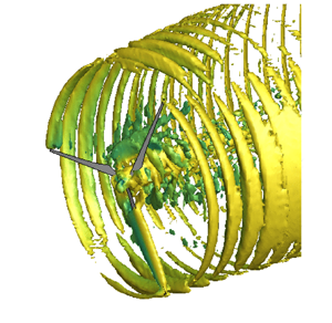
In this case, the uniform flow over a wind turbine, which produces a helical vortex system in its wake (Joukowski Reference Joukowski1912; Okulov et al. Reference Okulov, Naumov, Mikkelsen and Sørensen2015), is investigated. Here, we employ LES due to the high $Re$ to simulate the turbulent wake. The wind turbine rotor is modelled on the Clipper Liberty C96 2.5 MW turbine, with a diameter $D=96$, deployed at the University of Minnesota EOLOS Wind Energy Research Field Station in Rosemount, MN, USA due to both the fact that the LES methodology has been validated for this case (Yang et al. Reference Yang, Hong, Barone and Sotiropoulos2016; Foti, Yang & Sotiropoulos Reference Foti, Yang and Sotiropoulos2018b) and its well-documented description (Hong et al. Reference Hong, Toloui, Chamorro, Guala, Howard, Riley, Tucker and Sotiropoulos2014; Yang et al. Reference Yang, Hong, Barone and Sotiropoulos2016; Foti et al. Reference Foti, Yang and Sotiropoulos2018b). A constant tip-speed ratio $\varGamma = \varOmega D / 2 U_\infty = 8.0$, where $\varOmega$ is the rotor angular velocity and $U_\infty$ is the hub height velocity, is enforced on the rotation of the turbine as employed in previous simulations (Yang et al. Reference Yang, Hong, Barone and Sotiropoulos2016; Foti et al. Reference Foti, Yang and Sotiropoulos2018b). The rotational speed is chosen to operate the variable-speed turbine in the optimal condition for maximum power production. The Reynolds number based on the incoming velocity ${Re} = U_\infty D/\nu$, where $\nu$ is the kinematic viscosity, is set to be $2\times 10^{7}$. Further information on the setup can be found from Qatramez & Foti (Reference Qatramez and Foti2021).

The sharp-interface immersed boundary method is too computationally expensive for a utility-scale wind turbine. Instead, the forces exerted by the wind turbine and nacelle are parameterized by the actuator surface model by Shen, Sørensen & Zhang (Reference Shen, Sørensen and Zhang2007) and for the nacelle by Yang & Sotiropoulos (Reference Yang and Sotiropoulos2018). The lift $\boldsymbol {L}=\tfrac {1}{2} \rho C_L c |\boldsymbol {V}_{rel}|^2\boldsymbol {n}_{L}$ and drag $\boldsymbol {D}=\tfrac {1}{2} \rho C_D c |\boldsymbol {V}_{rel}|^2\boldsymbol {n}_{D}$, where $C_L$ and $C_D$ are the lift and drag coefficients from a look-up table based on the value of angle of attack, $c$ is the chord, $\boldsymbol {V}_{rel}$ is the relative incoming velocity, and $\boldsymbol {n}_{L}$ and $\boldsymbol {n}_{D}$ are the unit vectors in the directions of lift and drag, respectively. The relative incoming velocity $\boldsymbol {V}_{rel} = u_x(\boldsymbol {X}_{LE})\boldsymbol {e}_x+(u_\theta (\boldsymbol {X}_{LE})-\varOmega r)\boldsymbol {e}_\theta$, where $\boldsymbol {X}_{LE}$ represents the leading edge coordinates of the blade, $\varOmega$ is the rotational speed of the rotor, and $\boldsymbol {e}_x$ and $\boldsymbol {e}_\theta$ are the unit vectors in the axial flow and rotor rotating directions, respectively. A smoothed discrete delta function procedure (Yang et al. Reference Yang, Zhang, Li and He2009) is employed to interpolate the flow velocity to and from the surfaces. Stall delay model (Du & Selig Reference Du and Selig1998) and the tip-loss correction (Shen et al. Reference Shen, Mikkelsen, Sørensen and Bak2005) are employed to take into account the three-dimensional effects on the blades. The blade geometry is represented by a surface formed by the chord lines at every radial location of the blade, and the nacelle is represented by the actual surface of the nacelle with distributed forces.

The idealized uniform inflow is employed to analyse the interscale dynamics in the vortex system created in the wake. The computational domain is set to be $L_x \times L_y \times L_z = 5D \times 4D \times 4D$, in the streamwise, vertical and spanwise directions, respectively. The domain is discretized with a stretched Cartesian grid $N_x \times N_y \times N_z = 336 \times 251 \times 251$, where a $2D \times 2D \times 2D$ uniform mesh with grid size of $D/50$ is located around the turbine blades. The grid is stretched towards all domain boundaries. The turbine is positioned $1.5D$ downwind of the inflow at the centre of the $y$$z$ plane. The solution is integrated forward in time with a time step $\Delta tU_\infty /D = TU_\infty /(750D)$, where $T$ is the time for a single rotor revolution. The simulation is first run to remove initial transients from the flow field. After the initial transients are removed, the solution is obtained for $170TD/U_\infty$ such that the second- and third-order velocity statistics are converged. The three-dimensional instantaneous velocity is acquired at uniform intervals of $TU_\infty /(30D)$.

An unsteady, turbulent wake forms behind the wind turbine despite the uniform inflow velocity due to vortex shedding off the rotating blades and the solidity of the rotor. Figure 16(a) shows the instantaneous streamwise velocity. There is a velocity deficit in the the streamwise velocity $u/U_\infty$ behind the rotor forming the outer wake and an inner wake behind the nacelle (Foti et al. Reference Foti, Yang, Guala and Sotiropoulos2016). Individual, strong vortices from the blade tips can be observed and continue to be identified over $0.5D$ behind the rotor plane. The instantaneous streamwise velocity also shows the formation of an inner wake along the centreline due to the blockage and drag on the nacelle. The nacelle creates a strong inner wake along the centreline, which induces an unstable hub vortex that expands radially outward. The hub vortex and root vortices formed at the root of the blades immediately interact and merge in the inner wake. The expansion of the inner wake intersects the outer wake several diameters downwind. The domain intentionally includes only $2.5D$ downwind for the subsequent analysis, but if extended further, wake meandering, a dynamic oscillation of the wake, would be present (Kang et al. Reference Kang, Yang and Sotiropoulos2014; Foti et al. Reference Foti, Yang, Guala and Sotiropoulos2016, Reference Foti, Yang, Shen and Sotiropoulos2019). The unsteadiness and three-dimensionality of the tip vortices, root vortices and hub vortex wake are apparent in the iso-surface of the instantaneous azimuthal vorticity, $\omega _{\theta }D/U_\infty$, in figure 16(b). The specific vortices persist relatively far downwind due to a lack of incoming turbulence, which would induce breakdown further upwind. We can observe that relatively few strong coherent structures are present in the wake. Figure 16(c) shows the average streamwise vorticity, $\omega _x D/U_\infty$. The average vorticity shows clearly the signature of the strong tip vortices, root vortices and a hub vortex. The tip vortices remain strong throughout the domain, while the centreline vortices breakdown in the expanding inner wake.

Figure 16. (a) Instantaneous streamwise velocity $u/U_\infty$, (b) iso-surface of instantaneous azimuthal vorticity ($\omega _\theta D/U_\infty = 4$) coloured by the streamwise velocity and (c) average streamwise vorticity $\omega _x D/U_\infty$ in the wind turbine wake.

We perform DMD with $M=400$ snapshots, and the overall size of the snapshot matrix is $(N \times M) = 2.1 \times 10^6 \times 400$. The mean velocity is subtracted from the fluctuations and normalized, similar to previous cases. The time step between snapshots is $\Delta t_{DMD}/T = 1/25$, which is 30 times the temporal resolution of the LES and 8.3 times greater than the rotor frequency ${St}_r$. The maximum frequency captured by DMD is subject to the Nyquist criterion $f_{max} = 1 / (2\Delta t_{DMD})$. Further analysis on DMD hyper-parameter selection can be found from Qatramez & Foti (Reference Qatramez and Foti2021). Figure 17(a) shows the sparse sampling residual error in (4.1) as the sparsity increases. The error is zero for small values of $\gamma$ because all modes are selected. However, as $\gamma$ increases to no modes selected, $\epsilon _{sp} = 1$. We select three values: $R=391$, which is almost all modes, $R=106$ and $R=42$, which select only the most dominant modes. Elbow analysis of Qatramez & Foti (Reference Qatramez and Foti2021) is used to find the optimal $\gamma$ parameter for sparse sampling.

Figure 17. (a) Sparse sampling residual error $\epsilon _{sp}$ and number of retained modes based on sparsity parameter $\gamma$, (b) amplitudes $|\alpha _i|/\max (\alpha )$ and positive ${St}$ for selected modes (the vertical dotted red lines identify integer multiples of the shedding frequency), and (c) DMD reconstruction error, $\epsilon _u$, for select modes. All modes (green, square), $R=106$ selected modes (orange, triangle) and $R=42$ selected modes (blue, circle).

For all mode selections, the mode that is associated with rotor frequency ${St}_{r} = 7.62$ has the highest amplitude, indicating that this is the most dominant, energetic mode, as shown in figure 17(b). Multiples of the rotor frequency, $2{St}_{r}= 15.24$, and the blade frequency, $3{St}_{r} = {St}_b = 22.8$, are both present. Low frequency hub vortex mode, ${St}_h=2.5$, is also selected. The frequencies are consistent with previous studies (Iungo et al. Reference Iungo, Viola, Camarri, Porté-Agel and Gallaire2013; Foti et al. Reference Foti, Yang, Campagnolo, Maniaci and Sotiropoulos2018a) and are corroborated by spectral analysis of the velocity fluctuations from Qatramez & Foti (Reference Qatramez and Foti2021). Additionally, other relatively high amplitudes are related to the sum of the rotor and hub frequencies ${St}_{r,h} = 10.12$ and similar multiples. While $R=391$ selection contains a broad range of frequencies and the $R=43$ case selects only the hub and rotor frequencies, the $R=106$ case contains frequencies with the sum- and difference-interactions of the hub and rotor frequencies, which will be employed for further analysis of the energy transfer. The difference in reconstruction error, $\epsilon _u$, in (4.2) shows that there is significant energy in the largest 43 modes compared with the other modes.

The principle region of the bispectrum of the wind turbine wake is shown in figure 18. The intensity of the bispectrum is strongly oriented along frequencies that are multiples of the rotor frequency, ${St}_r$, including the blade frequency ${St}_b$. The strongest interaction is the self-interaction of $({St}_r, {St}_r)$, similar to the turbulent cylinder wake. Due to the zero-sum condition, this produces a frequency of $2{St}_r$. Additionally, the self-interaction of $({St}_r, -{St}_r)$ is strong creating interaction with the mean mode. The signs of the energy cascade to higher harmonics are evident with $({St}_r, 2{St}_r)$ to increase the blade frequency. Additionally, interactions of the hub vortex are also present. These include the self-interactions of the hub vortex such that peaks occur at $2{St}_h$. Multi-scale interactions of the hub vortex and rotor scales create peaks at frequencies at the sum of the hub and rotor frequency, ${St}_{r,h}$, and higher harmonics of the rotor at ${St}_{2r,h}$ and ${St}_{3r,h}$. These interactions are relatively high compared with other mode interactions that are selected with $R=106$, but not at the sparsest selection presented of $R=42$. Overall, the sparse sampling is able to capture the dominant interactions of the strongest coherent structures in the wake.

Figure 18. The principle region of bispectrum for all modes. The $R=42$ sparse-selected modes are outlined in blue and $R=106$ sparse-selected modes are outlined in green.

Figure 19 shows the scale-specific CKE of the four largest sum-interactions of the rotor frequency mode alone. These are all related to the interactions of the rotor with higher harmonics and demonstrate the energy cascade from the fundamental frequency of the rotation of the rotor and formation of the tip vortices to higher frequency modes. The sub-figures in figure 19 show the cascade from the fundamental rotor frequency to first harmonic to second harmonic, similar to figure 11. The scale-specific CKE related to the self-interaction, forming the first harmonic through sum-interaction, is the strongest sum-interaction component. It shows alternating wavenumber patterns of scale-specific CKE along the tip position and root vortices. This feeds into the interaction of the rotor frequency and first harmonic, $({St}_r, 2{St}_r)$, which is significantly smaller in magnitude than the self-interaction. The scale-specific CKE is predominantly near the root vortices, which quickly breakup due to the unstable hub vortex, while the scale-specific CKE near the tip positions is low. This suggests that the energy in the tip vortices remains in the rotor mode because they do not breakdown quickly due to the uniform inflow. The $({St}_r, 3{St}_r)$ and $({St}_r, 4{St}_r)$ behave similarly indicating scale-specific CKE near the centreline.

Figure 19. Scale-specific CKE $\tilde {k}^{l,m}$ related to the rotor mode. Note the change in scale.

The largest sum-interactions of the hub vortex scale-specific CKE are shown in figure 20. The four largest in magnitude are the interactions of the hub vortex with its fundamental frequency, first, second and third harmonic of the hub rotation. The majority of scale-specific CKE of each interaction is located near the centreline where the hub vortex forms behind the nacelle. The strength of the interaction is based on the sum- or difference-interactions. The strongest interactions are the sum-interaction of the first harmonic of the hub vortex and the hub vortex. The sum of the frequencies is approximately the same as the rotor frequency frequency. A difference-interaction of the first harmonic of the hub vortex and the hub vortex reveals how CKE in higher frequencies interact to produce energy in a lower frequency.

Figure 20. Scale-specific CKE $\tilde {k}^{l,m}$ related to the hub vortex mode frequency. Note the change in scale.

Next, we focus on the multi-scale nature of the sum-interactions of the rotor and hub vortex. Figure 21(a) shows the scale-specific CKE of the sum-interaction of the rotor and hub. The majority of CKE of each interaction is located near the centreline where the hub vortex and root vortices interact downwind of the nacelle. The CKE associated with the interactions suggests that the energy in this mode increases along the centreline due to the interactions of the hub vortex and root vortices. The most prominent is the hub vortex with the energy associated with the root vortices in the rotor frequency mode, but there is relatively high energy also associated with the interaction of the hub or rotor with the multi-scale ${St}_{r,h}$ scale-specific CKE. These interactions could be connected to the instability analysis of the hub vortex found from Iungo et al. (Reference Iungo, Viola, Camarri, Porté-Agel and Gallaire2013) and Viola et al. (Reference Viola, Iungo, Camarri, Porté-Agel and Gallaire2014) where multiple unstable mode growth rates are observed in the near wake along the centreline. In terms of sum-interactions, these interactions form energy associated with frequencies that are different than both the hub vortex and rotor frequencies, which gives rise to new frequencies and modes further downwind in the wake. Further study with larger domains are necessary to elucidate these effects. Figure 21(b) shows similar interaction of the hub and first harmonic of the rotor, which produces energy at a new frequency ${St}_{2r,h}$. Again significant energy is present near where the root vortices and the hub vortex interact near the centreline. The scale-specific CKE in these interactions persist downstream similar to observations by Foti et al. (Reference Foti, Yang, Guala and Sotiropoulos2016) of the persistence of the hub vortex.

Figure 21. Sum-interactions of scale-specific CKE $\tilde {k}^{l,m}$ related to (a) the rotor and hub vortex mode and (b) the first harmonic of the rotor and hub vortex. Note the change in scale.

Figure 22 show the four largest contributions of the summed scale-specific CKE. The largest contribution is the $l=0$ mean mode. The CKE in this scale represents all the sum- and difference-interactions that produce a frequency of 0. The kinetic energy is positive and highest along the tip shear layer and the centreline behind the nacelle. This is similar to the turbulence kinetic energy of wind turbine wakes shown by Foti (Reference Foti2016), Foti et al. (Reference Foti, Yang, Shen and Sotiropoulos2019) and Foti (Reference Foti2021). The next three scales are two orders of magnitude lower than the mean mode. These include energy associated with the rotor frequency, first harmonic of the rotor frequency and the hub vortex. The total CKE in the rotor frequency is spatially located near the rotor plane and root vortices. Similar behaviour is observed in the first harmonics. The summed scale-specific CKE in the hub vortex is present along the centreline where the hub vortex dominates.

Figure 22. Summed scale-specific CKE $\tilde {k}^{l}$ of four largest CKE contributions. Note the change in scale.

Energy transfer in the wind turbine vortex system is first accounted for by the scale-specific CKE production shown in figure 23(a) for the rotor and hub vortex. These indicate the spatial distribution where CKE is produced from the mean strain rates. For both, scale-specific CKE production is concentrated near the centreline due to the root and hub vortex. In the inner wake formed by the nacelle, there are strong mean velocity gradients in the radial direction, which account for the production of CKE into these scales. The overall interscale transfer to/from the rotor and hub vortex are shown in figure 23(b). These account for all energy transferred from all coherent scales to/from the rotor and hub vortex. There is significant energy transfer to the rotor mode along the rotor plane suggesting other scales are both sources and sinks of the rotor scale-specific CKE in the rotor plane. Additionally, there is significant transfer from the rotor frequency to the other modes near the presence of the root vortices. The overall energy transfer of the hub vortex shows how CKE in the hub vortex is transferred along the path of the hub vortex as it expands in the inner wake. This energy is a source to the new scales, ${St}_{r,h}$, etc.

Figure 23. Summed scale-specific (a) CKE production $\mathcal {P}^{l}$ and (b) interscale transfer $\mathcal {P}_t^l$ for the rotor and hub vortex modes. Note the change in scale.

The interscale transfer of the rotor is decomposed into some of the important contributions as shown in figure 24. The most significant is the interscale transfer triad of the rotor and the first harmonic of the rotor. There is positive and negative high transfer of CKE between the two modes. This occurs along the rotor plane, the tip shear layer and near the root vortices. The other three interscale transfers are the effects of interaction of hub and rotor modes, which transfer energy to scales that are initially formed by the rotation of the turbine blades. These interscale transfers show significant energy transfer between the root and hub vortices. Furthermore, the transfer persists downstream as hub vortex expands and the root vortices decay. In the study herein, we demonstrate that CKE of specific interactions and coherent structures can be appropriately identified, follow the sum-zero condition, and initiate the beginning of the nonlinear energy cascade.

Figure 24. Spatial distribution of the four largest triadic interscale transfers $\mathcal {P}_t^{l,m,n}$.

5. Conclusions

The scale-specific coherent kinetic energy (CKE) evolution methodology developed in this work provides an explicit formulation to study the implications of specific scales associated with coherent structures, triadic interactions and interscale energy dynamics in a wake. The kinetic energy of multiple specific coherent motions can be quantified based on spectral identification and spatial location. The methodology is subject to the sum-zero condition of triadic interactions, which is based on the quadratic nonlinearity of the governing equations. This is particularly useful in multi-scale flows that exhibit inhomogeneity and anisotropy due to the effects of the coherent structures. Triads between coherent scales can be easily identified and show how energy is transferred. The triads are detected as part of the bispectrum to determine the contributions of a triad of frequency scales to the energy transfer. The bispectrum and associated triads can be used to elucidate the energy cascade and nonlinear deviations. The balance of scale-specific CKE can be employed to reveal the impacts of energy transfer and transport on coherent structures. This includes quantifying production terms, which accounts for energy transfer from/to the mean or random components; interscale transfer terms, which identify energy transfer between specific coherent scales; and flux-like transport terms including pressure, viscosity and turbulence.

Specifically, we focus on the selection of the most dominant, large coherent scales in wake flows, which exemplify resonant triads of harmonics that distribute energy from a fundamental vortex shedding frequency. In this work, we quantified coherent scales based on the dynamic mode decomposition of the spatio-temporal flow field. This is employed because coherent scales in the flow are identified via their frequency, and it enables us to quantify the CKE of interactions between two modes. First, the methodology was applied to a low-Reynolds-number square cylinder wake flow, which produces dominant coherent structures that persist into the far field of the wake, as a validation test. Compressive sensing and various error residuals were used to determine an optimal set of modes. By minimizing the error in turbulence kinetic energy between CKE to ensure that the random kinetic energy is negligible, nearly all interactions from the largest to the smallest scales are captured. The set of modes were used to identify triads, distribution of CKE and validate the balance of scale-specific CKE.

The scale-specific CKE methodology was then used on a turbulent wake behind a square cylinder at ${Re}=3900$ and a wind turbine in uniform flow. Compressive sensing was used to determine the coherent scales through a set of modes that contained over 90 % of the energy. Overall, relatively few modes contain most of the CKE, which is dominated by the zero-frequency mode and the fundamental shedding frequency mode in the turbulent cylinder wake. Sum-interactions reveal complex interscale dynamics that overall follow the energy cascade; however, the exchange of energy between the coherent and random components and interscale transfer changes with downstream distance. The largest contributions reside in the sum- and difference-interactions of the shedding frequency mode. The balance of the scale-specific CKE for the largest scales reveals that pressure transport, mean convection and energy transfer terms balance, while overall dissipation, turbulence and viscous transport are RKE component mechanisms. The vortex system defined by tip/root vortices and the hub vortex of a wind turbine are the dominant structures in the wake. The scale-specific CKE enables the identification of the interactions between the two scales. It provides further evidence for the implications of the unstable hub vortex on dynamics of the downwind wake.

Finally, the present work constructs a methodology to analyse the energy transfer between coherent structures in a flow. Future work will consider the multi-scale interactions, where broad range and disparate scales dominant the flow. Scale selection will have to be carefully considered. Other scale identification methodologies such as spectral proper orthogonal decomposition (Towne et al. Reference Towne, Schmidt and Colonius2018), multi-scale filtering and bispectral mode decomposition (Schmidt Reference Schmidt2020) may be employed. Overall, the present work shows promise in elucidating details of coherent structure behaviour with respect to energy transfer.

Funding

This work supported by the National Science Foundation under grant no. 21-36371.

Declaration of interests

The authors report no conflict of interest.

Appendix A. Dynamic mode decomposition and compressive sensing

Koopman operator theory is a formalism that allows us to relate the observations on a system to the underlying state-space dynamics. In particular, we seek a Koopman-invariant subspace on the space of $\boldsymbol {u}$ that can be used to reduce the nonlinear spatio-temporal dynamics to a linear combination of time-evolving spatial modes through a Koopman mode decomposition. The Koopman operator $K_\tau$ acts on the observable of the state space of the flow $\boldsymbol {g}(\boldsymbol {u})$ to map the time evolution such that

(A1)\begin{equation} K_\tau \boldsymbol{g}(\boldsymbol{u}(\boldsymbol{x},t)) = \boldsymbol{g}(\boldsymbol{u}(\boldsymbol{x},t+\tau)). \end{equation}

The Koopman operator is a linear operator, which allows us to analyse its eigendecomposition and spectrum. The Koopman eigenfunction $\psi ^l_i(\boldsymbol {u})$ is identified by a eigenvalue, $\lambda ^l$, which we associate with a specific time scale. The eigenfunction associated with the Koopman operator is the following:

(A2)\begin{equation} K_\tau \psi^l(\boldsymbol{u}(\boldsymbol{x},t)) = {\rm e}^{\lambda^l t}\psi^l(\boldsymbol{u}(\boldsymbol{x},t)). \end{equation}

The eigenvalue is associated with a specific real-valued frequency $\lambda ^l = \textrm {i} \omega ^l$.

The Koopman mode decomposition is enabled by the expansion of the eigenfunctions

(A3)\begin{equation} K_\tau \boldsymbol{g}(\boldsymbol{u}) = \sum_{l=1}^\infty \boldsymbol{g}^l \psi^l(\boldsymbol{u}) {\rm e}^{\lambda^l \tau}, \end{equation}

where $\boldsymbol {g}^k$ are the Koopman modes obtained by projecting the observable into the eigenfunction. An important aspect of Koopman mode decomposition is that if two observables are related through a linear operator, then their modes are related through the same linear operator.

We detail to the algorithm used for sparsity-promoting DMD (Jovanović et al. Reference Jovanović, Schmid and Nichols2014). We define two matrices such that one is offset from the other by one time instance as follows:

(A4a,b)\begin{equation} X= \begin{bmatrix} \mid & \mid & \cdots & \mid\\ x_{1} & x_{2} & \cdots & x_{M-1}\\ \mid & \mid & \cdots & \mid \end{bmatrix}, \quad X^{'}= \begin{bmatrix} \mid & \mid & \cdots & \mid\\ x_{2} & x_{3} & \cdots & x_{M}\\ \mid & \mid & \cdots & \mid \end{bmatrix}, \end{equation}

where $X, X^\prime \in \mathcal {R}^{N \times M}$, $M$ is the number of degrees of freedom in a snapshot and $M$ is the number of snapshots. Each snapshot $x_i$ is uniformly sampled in time separated by a time step $\Delta t$. We employ the DMD algorithm derived by Schmid (Reference Schmid2010). The SVD of $X$ is computed as

(A5)\begin{equation} X = U \varSigma V^{{\rm T}}, \end{equation}

where ${\rm T}$ denotes the transpose, $U \in \mathcal {R}^{N \times S}$ are the left singular vectors, $\varSigma \in \mathcal {R}^{S \times S}$ is a diagonal matrix of the singular values, $V \in \mathcal {R}^{M \times S}$ are the right singular vector and $S$ is the rank of the reduced SVD. A reduced linear operator $\tilde {A} \in \mathcal {R}^{S \times S}$ can be efficiently obtained by projecting $A$ with the left singular vectors $U$ as follows:

(A6)\begin{equation} \tilde{A}= U^{*}A U = U^{*}X^{'}V \varSigma ^{{-}1}. \end{equation}

The matrix $\tilde {A}$ is the reduced mapping of the dynamical system. Spectral information of $\tilde {A}$, which has been shown to be the same as $A$, is obtained through an eigen-decomposition of $\tilde {A}$:

(A7)\begin{equation} \tilde{A}W=W\varLambda, \end{equation}

where columns of $W \in \mathcal {C}^{S \times S}$ are eigenvectors and $\varLambda \in \mathcal {C}^{S \times S}$ is a diagonal matrix containing the corresponding eigenvalues $\lambda = \lambda _r + \imath \lambda _{i}$. One can obtain the more familiar complex frequency, $\imath \omega _r = \log (\lambda _r) / \Delta t$. The real part is the temporal frequency and the imaginary part is an exponential growth rate of the dynamic mode. The matrix of the spatial dynamic modes $\varPhi \in \mathcal {C}^{M \times S}$ are recovered with the following:

(A8)\begin{equation} \varPhi = X^{'}V\varSigma ^{{-}1}W. \end{equation}

The optimal amplitudes $b$ can be solved through an $\mathrm {L}2$ minimization as the following:

(A9)\begin{equation} \underset{{\alpha}}{\mathrm{minimize}} \quad J(\alpha) = \|X-\varPhi D_{\alpha} V_{and} \|^{2}_{2}, \end{equation}

where $V_{and} \in \mathcal {R}^{S\times R}$ is the Vandermode matrix of the eigenvalues $\varLambda$. The row of the $V_{and}$ associated with the $k$th eigenvalue is $\mu ^k$. The calculation of the optimal amplitudes was simplified by Jovanović et al. (Reference Jovanović, Schmid and Nichols2014) to the following:

(A10)\begin{equation} J(\alpha) = \alpha^T P \alpha - q^T\alpha - \alpha^Tq + s, \end{equation}

where $P=(W^T W) \odot (V_{and} V_{and}^T)^*$, $q = (\mathrm {diag}(V_{and}V \varSigma W))^*$ and $s = \mathrm {trace}(\varSigma ^T \varSigma )$. A sparse solution is induced by including the L1-norm of vector $\alpha$ to the optimization problem in (A10):

(A11)\begin{equation} \underset{{\alpha}}{\mathrm{minimize}} \quad J(\alpha) + \gamma \sum_{i=1}^{R} |\alpha_{i}|, \end{equation}

where $\gamma$ is a positive parameter that controls the sparse solution of the amplitudes vector $\alpha$. The solution is obtained by solving the optimization using the alternating direct method of multiples. The sparsity-promoting DMD algorithm trained on a L1 norm regularization (Jovanović et al. Reference Jovanović, Schmid and Nichols2014) and a multi-task elastic net trained on a L1/L2 norm regularization (Pan, Arnold-Medabalimi & Duraisamy Reference Pan, Arnold-Medabalimi and Duraisamy2020) produce similar results for sparsification of the resultant DMD modes.

Appendix B. Validation of square cylinder DNS

In this section, we provide a detailed comparison of the velocity statistics from the square cylinder DNS discussed in § 4.2 to experimental measurements and previous DNS studies. Figure 25(a) shows the profile of the average streamwise velocity $U/U_\infty$ along the $y=0$ centreline from the DNS and results from experimental studies (Durao, Heitor & Pereira Reference Durao, Heitor and Pereira1988; Lyn et al. Reference Lyn, Einav, Rodi and Park1995; Lee & Kim Reference Lee and Kim2001; Hu, Zhou & Dalton Reference Hu, Zhou and Dalton2006) and DNS studies (Arslan et al. Reference Arslan, El Khoury, Pettersen and Andersson2012; Trias, Gorobets & Oliva Reference Trias, Gorobets and Oliva2015; Portela et al. Reference Portela, Papadakis and Vassilicos2017). The profile throughout the entire domain falls well within the range previous experimental studies and follow the trends of the DNS studies, in particular, Portela et al. (Reference Portela, Papadakis and Vassilicos2017), which is performed at the same $Re$. Significant ranges in the mean velocity in the experimental studies are observed in the rear stagnation point and near wake due to blockage, $Re$, and incoming turbulence levels. However, broad agreement with DNS studies are observed near the stagnation point and in the wake recovery. Further downstream, the profiles of DNS studies tend to agree with respect to the present work.

Figure 25. (a) Profiles of mean streamwise velocity $U$, (b) standard deviation of the streamwise velocity $u^\prime$, and (c) standard deviation of the vertical velocity fluctuations $v^\prime$ with experimental measurements and DNS results over a range of relevant ${Re}$.

Figure 25(b,c) show the differences among the experimental measurements, DNS studies, and the present results of the streamwise and vertical standard deviation of the velocity fluctuations, respectively. Similar to the mean streamwise velocity, the turbulent fluctuations in the near wake show large variation in the experiments. The large values of $u^\prime$ observed in $x/D < -0.5$ by Durao et al. (Reference Durao, Heitor and Pereira1988) are due to their relatively high turbulence in the incoming velocity. The streamwise and vertical fluctuations peak around $x \approx D$ for both the streamwise and vertical components. Differences in peak value can be attributed to different methodologies and experimental procedures. The present results tend to closely follow those of the DNS studies.

References

Alexakis, A. & Biferale, L. 2018 Cascades and transitions in turbulent flows. Phys. Rep. 767, 1101.CrossRefGoogle Scholar
Armenio, V. & Piomelli, U. 2000 A Lagrangian mixed subgrid-scale model in generalized coordinates. Flow Turbul. Combust. 65 (1), 5181.CrossRefGoogle Scholar
Arslan, T., El Khoury, G.K., Pettersen, B. & Andersson, H.I. 2012 Simulations of flow around a three-dimensional square cylinder using LES and DNS. In The Seventh International Colloquium on Bluff Body Aerodynamics and Applications, Shanghai, China, pp. 909–918. International Association for Wind Engineering.Google Scholar
Bai, H. & Alam, M.M. 2018 Dependence of square cylinder wake on Reynolds number. Phys. Fluids 30 (1), 015102.CrossRefGoogle Scholar
Baj, P. & Buxton, O.R.H. 2017 Interscale energy transfer in the merger of wakes of a multiscale array of rectangular cylinders. Phys. Rev. Fluids 2 (11), 114607.CrossRefGoogle Scholar
Berkooz, G., Holmes, P. & Lumley, J.L. 1993 The proper orthogonal decomposition in the analysis of turbulent flows. Annu. Rev. Fluid Mech. 25 (1), 539575.CrossRefGoogle Scholar
Biswas, N., Cicolin, M.M. & Buxton, O.R.H. 2022 Energy exchanges in the flow past a cylinder with a leeward control rod. J. Fluid Mech. 941, A36.CrossRefGoogle Scholar
Borazjani, I., Ge, L. & Sotiropoulos, F. 2008 Curvilinear immersed boundary method for simulating fluid structure interaction with complex 3D rigid bodies. J. Comput. Phys. 227 (16), 75877620.CrossRefGoogle ScholarPubMed
Brasseur, J.G. & Wei, C.-H. 1994 Interscale dynamics and local isotropy in high Reynolds number turbulence within triadic interactions. Phys. Fluids 6 (2), 842870.CrossRefGoogle Scholar
Brown, G.L. & Roshko, A. 1974 On density effects and large structure in turbulent mixing layers. J. Fluid Mech. 64 (4), 775816.CrossRefGoogle Scholar
Cal, R.B., Lebrón, J., Castillo, L., Kang, H.S. & Meneveau, C. 2010 Experimental study of the horizontally averaged flow structure in a model wind-turbine array boundary layer. J. Renew. Sustain. Energy 2 (1), 013106.CrossRefGoogle Scholar
Calaf, M., Meneveau, C. & Meyers, J. 2010 Large eddy simulation study of fully developed wind-turbine array boundary layers. Phys. Fluids 22 (1), 015110.CrossRefGoogle Scholar
Cantwell, B.J. 1981 Organized motion in turbulent flow. Annu. Rev. Fluid Mech. 13 (1), 457515.CrossRefGoogle Scholar
Carbone, M. & Bragg, A.D. 2020 Is vortex stretching the main cause of the turbulent energy cascade? J. Fluid Mech. 883, R2.CrossRefGoogle Scholar
Cerutti, S. & Meneveau, C. 1998 Intermittency and relative scaling of subgrid-scale energy dissipation in isotropic turbulence. Phys. Fluids 10 (4), 928937.CrossRefGoogle Scholar
Chan, C.I., Schlatter, P. & Chin, R.C. 2021 Interscale transport mechanisms in turbulent boundary layers. J. Fluid Mech. 921, A13.CrossRefGoogle Scholar
Chen, X., Yao, J. & Hussain, F. 2021 Theoretical framework for energy flux analysis of channels under drag control. Phys. Rev. Fluids 6 (1), 013902.CrossRefGoogle Scholar
Chrisohoides, A. & Sotiropoulos, F. 2003 Experimental visualization of Lagrangian coherent structures in aperiodic flows. Phys. Fluids 15 (3), L25L28.CrossRefGoogle Scholar
Cimarelli, A., De Angelis, E., Jimenez, J. & Casciola, C.M. 2016 Cascades and wall-normal fluxes in turbulent channel flows. J. Fluid Mech. 796, 417436.CrossRefGoogle Scholar
Cohen, L. 1995 Time-Frequency Analysis, vol. 778. Prentice Hall.Google Scholar
Corke, T.C., Shakib, F. & Nagib, H.M. 1991 Mode selection and resonant phase locking in unstable axisymmetric jets. J. Fluid Mech. 223, 253311.CrossRefGoogle Scholar
Domaradzki, J.A., Liu, W. & Brachet, M.E. 1993 An analysis of subgrid-scale interactions in numerically simulated isotropic turbulence. Phys. Fluids A 5 (7), 17471759.CrossRefGoogle Scholar
Domaradzki, J.A., Liu, W., Härtel, C. & Kleiser, L. 1994 Energy transfer in numerically simulated wall-bounded turbulent flows. Phys. Fluids 6 (4), 15831599.CrossRefGoogle Scholar
Domaradzki, J.A. & Rogallo, R.S. 1990 Local energy transfer and nonlocal interactions in homogeneous, isotropic turbulence. Phys. Fluids A 2 (3), 413426.CrossRefGoogle Scholar
Dong, S., Huang, Y., Yuan, X. & Lozano-Durán, A. 2020 The coherent structure of the kinetic energy transfer in shear turbulence. J. Fluid Mech. 892, A22.CrossRefGoogle Scholar
Donoho, D.L. 2006 Compressed sensing. IEEE Trans. Inf. Theory 52 (4), 12891306.CrossRefGoogle Scholar
Du, Z. & Selig, M. 1998 A 3-D stall-delay model for horizontal axis wind turbine performance prediction. In 1998 ASME Wind Energy Symposium, Reno, NV, USA, p. 21. American Institute of Aeronautics and Astronautics.CrossRefGoogle Scholar
Dubief, Y. & Delcayre, F. 2000 On coherent-vortex identification in turbulence. J. Turbul. 1 (1), 011011.CrossRefGoogle Scholar
Dubrulle, B. 2019 Beyond Kolmogorov cascades. J. Fluid Mech. 867, P1.CrossRefGoogle Scholar
Durao, D.F.G., Heitor, M.V. & Pereira, J.C.F. 1988 Measurements of turbulent and periodic flows around a square cross-section cylinder. Exp. Fluids 6 (5), 298304.CrossRefGoogle Scholar
Farazmand, M. & Sapsis, T.P. 2017 A variational approach to probing extreme events in turbulent dynamical systems. Sci. Adv. 3 (9), e1701533.CrossRefGoogle ScholarPubMed
Foti, D. 2016 Quantification and reduction of uncertainty of model predictions of wind turbines and plants via high-fidelity simulations. PhD thesis, University of Minnesota, Minneapolis, MN.Google Scholar
Foti, D. 2021 Coherent vorticity dynamics and dissipation in a utility-scale wind turbine wake with uniform inflow. Theor. Appl. Mech. Lett. 11 (5), 100292.CrossRefGoogle Scholar
Foti, D., Giorno, S. & Duraisamy, K. 2020 An adaptive mesh refinement approach based on optimal sparse sensing. Theor. Comput. Fluid Dyn. 34 (4), 457482.CrossRefGoogle Scholar
Foti, D., Yang, X., Campagnolo, F., Maniaci, D. & Sotiropoulos, F. 2018 a Wake meandering of a model wind turbine operating in two different regimes. Phys. Rev. Fluids 3 (5), 054607.CrossRefGoogle Scholar
Foti, D., Yang, X., Guala, M. & Sotiropoulos, F. 2016 Wake meandering statistics of a model wind turbine: insights gained by large eddy simulations. Phys. Rev. Fluids 1 (4), 044407.CrossRefGoogle Scholar
Foti, D., Yang, X., Shen, L. & Sotiropoulos, F. 2019 Effect of wind turbine nacelle on turbine wake dynamics in large wind farms. J. Fluid Mech. 869, 126.CrossRefGoogle Scholar
Foti, D., Yang, X. & Sotiropoulos, F. 2018 b Similarity of wake meandering for different wind turbine designs for different scales. J. Fluid Mech. 842, 525.CrossRefGoogle Scholar
Fowler, J.E. 2009 Compressive-projection principal component analysis. IEEE Trans. Image Process. 18 (10), 22302242.CrossRefGoogle ScholarPubMed
Gatti, D., Chiarini, A., Cimarelli, A. & Quadrio, M. 2020 Structure function tensor equations in inhomogeneous turbulence. J. Fluid Mech. 898, A5.CrossRefGoogle Scholar
Gatti, D., Cimarelli, A., Hasegawa, Y., Frohnapfel, B. & Quadrio, M. 2018 Global energy fluxes in turbulent channels with flow control. J. Fluid Mech. 857, 345373.CrossRefGoogle Scholar
Ge, L. & Sotiropoulos, F. 2007 A numerical method for solving the 3D unsteady incompressible Navier–Stokes equations in curvilinear domains with complex immersed boundaries. J. Comput. Phys. 225 (2), 17821809.CrossRefGoogle ScholarPubMed
Gee, K.L., Atchley, A.A., Falco, L.E., Shepherd, M.R., Ukeiley, L.S., Jansen, B.J. & Seiner, J.M. 2010 Bicoherence analysis of model-scale jet noise. J. Acoust. Soc. Am. 128 (5), EL211EL216.CrossRefGoogle ScholarPubMed
Germano, M., Piomelli, U., Moin, P. & Cabot, W.H. 1991 A dynamic subgrid-scale eddy viscosity model. Phys. Fluids A 3 (7), 17601765.CrossRefGoogle Scholar
Gomes-Fernandes, R., Ganapathisubramani, B. & Vassilicos, J.C. 2015 The energy cascade in near-field non-homogeneous non-isotropic turbulence. J. Fluid Mech. 771, 676705.CrossRefGoogle Scholar
Goto, S., Saito, Y. & Kawahara, G. 2017 Hierarchy of antiparallel vortex tubes in spatially periodic turbulence at high Reynolds numbers. Phys. Rev. Fluids 2 (6), 064603.CrossRefGoogle Scholar
Guala, M., Hommema, S.E. & Adrian, R.J. 2006 Large-scale and very-large-scale motions in turbulent pipe flow. J. Fluid Mech. 554, 521542.CrossRefGoogle Scholar
Haller, G. 2015 Lagrangian coherent structures. Annu. Rev. Fluid Mech. 47, 137162.CrossRefGoogle Scholar
Hamilton, J.M., Kim, J. & Waleffe, F. 1995 Regeneration mechanisms of near-wall turbulence structures. J. Fluid Mech. 287 (1), 317348.CrossRefGoogle Scholar
Hill, R.J. 2002 Exact second-order structure-function relationships. J. Fluid Mech. 468, 317326.CrossRefGoogle Scholar
Holmes, P., Lumley, J.L., Berkooz, G. & Rowley, C.W. 2012 Turbulence, Coherent Structures, Dynamical Systems and Symmetry. Cambridge University Press.CrossRefGoogle Scholar
Hong, J., Katz, J., Meneveau, C. & Schultz, M.P. 2012 Coherent structures and associated subgrid-scale energy transfer in a rough-wall turbulent channel flow. J. Fluid Mech. 712, 92128.CrossRefGoogle Scholar
Hong, J., Toloui, M., Chamorro, L.P., Guala, M., Howard, K., Riley, S., Tucker, J. & Sotiropoulos, F. 2014 Natural snowfall reveals large-scale flow structures in the wake of a 2.5-MW wind turbine. Nat. Commun. 5, 4216.CrossRefGoogle ScholarPubMed
Hu, J.C., Zhou, Y. & Dalton, C. 2006 Effects of the corner radius on the near wake of a square prism. Exp. Fluids 40, 106118.CrossRefGoogle Scholar
Hunt, J.C.R., Wray, A.A. & Moin, P. 1988 Eddies, streams, and convergence zones in turbulent flows. In Center for Turbulence Research, Proceedings of the Summer Program 1988, Center for Turbulence Research Report CTR-S88, pp. 193–208. Center for Turbulence Research.Google Scholar
Hussain, A.K.M.F. 1983 Coherent structures—reality and myth. Phys. Fluids 26 (10), 28162850.CrossRefGoogle Scholar
Hussain, A.K.M. 1986 Coherent structures and turbulence. J. Fluid Mech. 173, 303356.CrossRefGoogle Scholar
Hussain, A.K.M.F. & Reynolds, W.C. 1970 The mechanics of an organized wave in turbulent shear flow. J. Fluid Mech. 41 (2), 241258.CrossRefGoogle Scholar
Hussain, A.K.M.F. & Zaman, K.B.M.Q. 1985 An experimental study of organized motions in the turbulent plane mixing layer. J. Fluid Mech. 159, 85104.CrossRefGoogle Scholar
Hutchins, N. & Marusic, I. 2007 Evidence of very long meandering features in the logarithmic region of turbulent boundary layers. J. Fluid Mech. 579, 128.CrossRefGoogle Scholar
Iungo, G.V., Viola, F., Camarri, S., Porté-Agel, F. & Gallaire, F. 2013 Linear stability analysis of wind turbine wakes performed on wind tunnel measurements. J. Fluid Mech. 737, 499526.CrossRefGoogle Scholar
Jeong, J. & Hussain, F. 1995 On the identification of a vortex. J. Fluid Mech. 285, 6994.CrossRefGoogle Scholar
Jiménez, J. 2018 Coherent structures in wall-bounded turbulence. J. Fluid Mech. 842, P1.CrossRefGoogle Scholar
Jin, B., Symon, S. & Illingworth, S.J. 2021 Energy transfer mechanisms and resolvent analysis in the cylinder wake. Phys. Rev. Fluids 6 (2), 024702.CrossRefGoogle Scholar
Joukowski, N.E. 1912 Vortex theory of a rowing screw. Trudy Otdeleniya Fizicheskikh Nauk Obshchestva Lubitelei Estestvoznaniya 16 (1), 1–31.Google Scholar
Jovanović, M.R., Schmid, P.J. & Nichols, J.W. 2014 Sparsity-promoting dynamic mode decomposition. Phys. Fluids 26 (2), 024103.CrossRefGoogle Scholar
Kang, S., Lightbody, A., Hill, C. & Sotiropoulos, F. 2011 High-resolution numerical simulation of turbulence in natural waterways. Adv. Water Resour. 34 (1), 98113.CrossRefGoogle Scholar
Kang, S., Yang, X. & Sotiropoulos, F. 2014 On the onset of wake meandering for an axial flow turbine in a turbulent open channel flow. J. Fluid Mech. 744, 376403.CrossRefGoogle Scholar
Kolmogorov, A.N. 1941 The local structure of turbulence in incompressible viscous fluid for very large Reynolds numbers. Cr Acad. Sci. URSS 30, 301305.Google Scholar
Kraichnan, R.H. 1967 Inertial ranges in two-dimensional turbulence. Phys. Fluids 10 (7), 14171423.CrossRefGoogle Scholar
Kraichnan, R.H. 1971 Inertial-range transfer in two-and three-dimensional turbulence. J. Fluid Mech. 47 (3), 525535.CrossRefGoogle Scholar
Kravchenko, A.G., Choi, H. & Moin, P. 1993 On the relation of near-wall streamwise vortices to wall skin friction in turbulent boundary layers. Phys. Fluids A 5 (12), 33073309.CrossRefGoogle Scholar
Kutz, J.N. 2013 Data-Driven Modeling & Scientific Computation: Methods for Complex Systems & Big Data. Oxford University Press.Google Scholar
Lee, M.-B. & Kim, G.-C. 2001 A study on the near wake of a square cylinder using particle image velocimetry (i)-mean flow field. Trans. Korean Soc. Mech. Engrs B 25 (10), 14081416.Google Scholar
Lii, K.S., Rosenblatt, M. & Van Atta, C. 1976 Bispectral measurements in turbulence. J. Fluid Mech. 77 (1), 4562.CrossRefGoogle Scholar
Lyn, D.A., Einav, S., Rodi, W. & Park, J.-H. 1995 A laser-doppler velocimetry study of ensemble-averaged characteristics of the turbulent near wake of a square cylinder. J. Fluid Mech. 304, 285319.CrossRefGoogle Scholar
McKeon, B.J. & Sharma, A.S. 2010 A critical-layer framework for turbulent pipe flow. J. Fluid Mech. 658, 336382.CrossRefGoogle Scholar
Mezić, I. 2013 Analysis of fluid flows via spectral properties of the Koopman operator. Annu. Rev. Fluid Mech. 45, 357378.CrossRefGoogle Scholar
Mininni, P.D., Alexakis, A. & Pouquet, A. 2006 Large-scale flow effects, energy transfer, and self-similarity on turbulence. Phys. Rev. E 74 (1), 016303.CrossRefGoogle ScholarPubMed
Mizota, T. & Okajima, A. 1981 Experimental studies of time mean flows around rectangular prisms. In Proceedings of the Japan Society of Civil Engineers, vol. 1981, pp. 39–47. Japan Society of Civil Engineers.CrossRefGoogle Scholar
Motoori, Y. & Goto, S. 2019 Generation mechanism of a hierarchy of vortices in a turbulent boundary layer. J. Fluid Mech. 865, 10851109.CrossRefGoogle Scholar
Norberg, C. 1993 Flow around rectangular cylinders: pressure forces and wake frequencies. J. Wind Engng Ind. Aerodyn. 49 (1–3), 187196.CrossRefGoogle Scholar
Okulov, V.L., Naumov, I.V., Mikkelsen, R.F. & Sørensen, J.N. 2015 Wake effect on a uniform flow behind wind-turbine model. In Journal of Physics: Conference Series, vol. 625, p. 012011. IOP.CrossRefGoogle Scholar
Pan, S., Arnold-Medabalimi, N. & Duraisamy, K. 2020 Sparsity-promoting algorithms for the discovery of informative koopman invariant subspaces. J. Fluid Mech. 917, A18.Google Scholar
Piomelli, U., Cabot, W.H., Moin, P. & Lee, S. 1991 Subgrid-scale backscatter in turbulent and transitional flows. Phys. Fluids A 3 (7), 17661771.CrossRefGoogle Scholar
Piomelli, U., Yu, Y. & Adrian, R.J. 1996 Subgrid-scale energy transfer and near-wall turbulence structure. Phys. Fluids 8 (1), 215224.CrossRefGoogle Scholar
Portela, F.A., Papadakis, G. & Vassilicos, J.C. 2017 The turbulence cascade in the near wake of a square prism. J. Fluid Mech. 825, 315352.CrossRefGoogle Scholar
Qatramez, A. & Foti, D. 2021 Reduced-order model predictions of wind turbines via mode decomposition and sparse sampling. In AIAA Scitech 2021 Forum, p. 1602. American Institute of Aeronautics and Astronautics.CrossRefGoogle Scholar
Reynolds, W.C. & Hussain, A.K.M.F. 1972 The mechanics of an organized wave in turbulent shear flow. Part 3. Theoretical models and comparisons with experiments. J. Fluid Mech. 54 (2), 263288.CrossRefGoogle Scholar
Richardson, L.F. 1922 Weather Prediction by Numerical Process. Cambridge University Press.Google Scholar
Robinson, S.K. 1991 Coherent motions in the turbulent boundary layer. Annu. Rev. Fluid Mech. 23 (1), 601639.CrossRefGoogle Scholar
Rowley, C.W., Colonius, T. & Murray, R.M. 2004 Model reduction for compressible flows using POD and Galerkin projection. Physica D 189 (1–2), 115129.CrossRefGoogle Scholar
Rowley, C.W., Mezic, I., Bagheri, S., Schlatter, P. & Henningson, D. 2009 Spectral analysis of nonlinear flows. J. Fluid Mech. 641 (1), 115127.CrossRefGoogle Scholar
Schmid, P.J. 2010 Dynamic mode decomposition of numerical and experimental data. J. Fluid Mech. 656, 528.CrossRefGoogle Scholar
Schmidt, O.T. 2020 Bispectral mode decomposition of nonlinear flows. Nonlinear Dyn. 102 (4), 24792501.CrossRefGoogle Scholar
Schmidt, O.T., Towne, A., Colonius, T., Cavalieri, A.V.G., Jordan, P. & Brès, G.A. 2017 Wavepackets and trapped acoustic modes in a turbulent jet: coherent structure eduction and global stability. J. Fluid Mech. 825, 11531181.CrossRefGoogle Scholar
Sharma, A. & Eswaran, V. 2004 Heat and fluid flow across a square cylinder in the two-dimensional laminar flow regime. Numer. Heat Transfer A 45 (3), 247269.CrossRefGoogle Scholar
Shen, W.Z., Mikkelsen, R., Sørensen, J.N. & Bak, C. 2005 Tip loss corrections for wind turbine computations. Wind Energy 8 (4), 457475.CrossRefGoogle Scholar
Shen, W.Z., Sørensen, J.N. & Zhang, J. 2007 Actuator surface model for wind turbine flow computations. In Proceedings of European Wind Energy Conference & Exhibition 2007.Google Scholar
Sirovich, L. 1987 Turbulence and the dynamics of coherent structures. I. Coherent structures. Q. Appl. Maths 45 (3), 561571.CrossRefGoogle Scholar
Smagorinsky, J. 1963 General circulation experiments with the primitive equations. I. The basic experiment. Mon. Weath. Rev. 91 (3), 99164.2.3.CO;2>CrossRefGoogle Scholar
Sohankar, A., Norberg, C. & Davidson, L. 1999 Simulation of three-dimensional flow around a square cylinder at moderate Reynolds numbers. Phys. Fluids 11 (2), 288306.CrossRefGoogle Scholar
Symon, S., Illingworth, S.J. & Marusic, I. 2021 Energy transfer in turbulent channel flows and implications for resolvent modelling. J. Fluid Mech. 911, A3.CrossRefGoogle Scholar
Thiesset, F., Danaila, L., A Antonia, R. & Zhou, T. 2011 Scale-by-scale energy budgets which account for the coherent motion. In Journal of Physics: Conference Series, vol. 318, p. 052040. IOP.CrossRefGoogle Scholar
Thiesset, F., Danaila, L. & Antonia, R.A. 2014 Dynamical interactions between the coherent motion and small scales in a cylinder wake. J. Fluid Mech. 749, 201226.CrossRefGoogle Scholar
Towne, A., Schmidt, O.T. & Colonius, T. 2018 Spectral proper orthogonal decomposition and its relationship to dynamic mode decomposition and resolvent analysis. J. Fluid Mech. 847, 821867.CrossRefGoogle Scholar
Trias, F.X., Gorobets, A. & Oliva, A. 2015 Turbulent flow around a square cylinder at Reynolds number 22,000: a DNS study. Comput. Fluids 123, 8798.CrossRefGoogle Scholar
Valente, P.C. & Vassilicos, J.C. 2015 The energy cascade in grid-generated non-equilibrium decaying turbulence. Phys. Fluids 27 (4), 045103.CrossRefGoogle Scholar
VerHulst, C. & Meneveau, C. 2015 Altering kinetic energy entrainment in large eddy simulations of large wind farms using unconventional wind turbine actuator forcing. Energies 8 (1), 370386.CrossRefGoogle Scholar
Viola, F., Iungo, G.V., Camarri, S., Porté-Agel, F. & Gallaire, F. 2014 Prediction of the hub vortex instability in a wind turbine wake: stability analysis with eddy-viscosity models calibrated on wind tunnel data. J. Fluid Mech. 750, R1.CrossRefGoogle Scholar
Waleffe, F. 1992 The nature of triad interactions in homogeneous turbulence. Phys. Fluids A 4 (2), 350363.CrossRefGoogle Scholar
Waleffe, F. 1997 On a self-sustaining process in shear flows. Phys. Fluids 9 (4), 883900.CrossRefGoogle Scholar
Williamson, C.H.K. 1996 Vortex dynamics in the cylinder wake. Annu. Rev. Fluid Mech. 28 (1), 477539.CrossRefGoogle Scholar
Wygnanski, I., Champagne, F. & Marasli, B. 1986 On the large-scale structures in two-dimensional, small-deficit, turbulent wakes. J. Fluid Mech. 168, 3171.CrossRefGoogle Scholar
Yang, X., Hong, J., Barone, M. & Sotiropoulos, F. 2016 Coherent dynamics in the rotor tip shear layer of utility-scale wind turbines. J. Fluid Mech. 804, 90115.CrossRefGoogle Scholar
Yang, X., Howard, K.B., Guala, M. & Sotiropoulos, F. 2015 Effects of a three-dimensional hill on the wake characteristics of a model wind turbine. Phys. Fluids 27 (2), 025103.CrossRefGoogle Scholar
Yang, X. & Sotiropoulos, F. 2018 A new class of actuator surface models for wind turbines. Wind Energy 21 (5), 285302.CrossRefGoogle Scholar
Yang, X., Zhang, X., Li, Z. & He, G.-W. 2009 A smoothing technique for discrete delta functions with application to immersed boundary method in moving boundary simulations. J. Comput. Phys. 228 (20), 78217836.CrossRefGoogle Scholar
Zaman, K.B.M.Q. 1996 Axis switching and spreading of an asymmetric jet: the role of coherent structure dynamics. J. Fluid Mech. 316, 127.CrossRefGoogle Scholar
Zhou, Y., Nagata, K., Sakai, Y. & Watanabe, T. 2019 Extreme events and non-Kolmogorov $-5/3$ spectra in turbulent flows behind two side-by-side square cylinders. J. Fluid Mech. 874, 677698.CrossRefGoogle Scholar
Zhou, Y., Nagata, K., Sakai, Y., Watanabe, T., Ito, Y. & Hayase, T. 2020 Energy transfer in turbulent flows behind two side-by-side square cylinders. J. Fluid Mech. 903, A4.CrossRefGoogle Scholar
Figure 0

Figure 1. Regions of the bispectrum. The dark shaded region outlined in red is the principal region and corresponds to sum-interactions. The light shaded region outlined in blue is the conjugate region and corresponds to difference-interactions. Redundancy are outlined by dashed lines with the colour corresponding to region.

Figure 1

Figure 2. (a) Instantaneous out-of-plane vorticity $\omega _z D/U_\infty$, (b) coherent kinetic energy $\tilde {k}/U_\infty ^2$ and (c) the power spectral density of the streamwise velocity $E_{uu}$ at $x/D=1$ and $x/D=9$ along the centreline. Vertical dotted red lines indicate multiples of ${St}/{St}_s = \{1, 2, 3, 4\}$.

Figure 2

Figure 3. (a) The singular values $\sigma _i$ and the cumulative TKE, $\sum _{i=0}^S \sigma _i^2/\sum _{i=0}^N \sigma _i^2$. Vertical lines show 99 %, 99.9 %, 99.99 % and 99.999 % of cumulative TKE. (b) The error metrics $\epsilon _{sp}$, $\epsilon _u$ and $\epsilon _k$ based on the number of selected modes $R$. Colour scheme is same as in panel (a).

Figure 3

Figure 4. (a) Amplitudes $|\alpha _i|/\max (\alpha )$ and positive ${St}$ for 99 %, 99.9 %, 99.99 % and 99.999 % of cumulative TKE. The vertical dotted red lines identify integer multiples of the shedding frequency. (b) Streamwise velocity modes $\phi _u$ and (c) kinetic energy modes $\phi _k$ with the four largest amplitudes.

Figure 4

Figure 5. The principle region of triad correlations for (a) sampled modes and (b) total modes containing 99.99 % of cumulative TKE.

Figure 5

Figure 6. Contours of the (a) summed scale-specific CKE $\tilde {k}^l$ where $l=0{St}_s - 3{St}_s$ and (b) scale-specific CKE $\tilde {k}^{l,m}$ are the three largest components. The $l$ and $m$ superscripts refer to integer multiples of ${St}_s$.

Figure 6

Figure 7. (a) Instantaneous vertical velocity $v/U_\infty$, (b) instantaneous out-of-plane vorticity $\omega _z D/U_\infty$, (c) turbulence kinetic energy $k^\prime /U_\infty ^2$, (d) the power spectral density of the streamwise velocity $E_{uu}$ and (e) the $5/3$ compensated power spectral density of the vertical velocity $f^{-5/3}E_{vv}$. Vertical dotted red lines labelled on spectra indicate multiples of ${St}_s$.

Figure 7

Figure 8. (a) Amplitudes $|\alpha _i|/\max (\alpha )$ and positive ${St}$ for 99 % of cumulative TKE and selected modes through sparse sampling. The vertical dotted red lines identify integer multiples of the shedding frequency. (b) Streamwise velocity modes $\phi _u$ with the four largest amplitudes.

Figure 8

Figure 9. (a) The principle region of bispectrum for all modes containing 99 % of cumulative TKE and sparse-selected modes. (b) Zoomed-in view.

Figure 9

Figure 10. Summed bispectrum for all modes containing 99 % of cumulative TKE and sparse-selected modes. Vertical lines are integer multiples (1–14) of the shedding frequency.

Figure 10

Figure 11. The scale-specific CKE $\tilde {k}^{l,m}$ of several sum-interaction modes related the shedding frequency.

Figure 11

Figure 12. The summed scale-specific CKE $\tilde {k}^{l}$ of largest CKE contributions.

Figure 12

Figure 13. Terms of the scale-specific CKE balance of the four largest frequency modes: $0, {St}_s, 2{St}_s,$ and $3{St}_s$ at the centreline at (a) $x/D=0.5$, (b) $1$, (c) $1.5$ and (d) $2$. Values are expressed as a fraction of the respective total gains.

Figure 13

Figure 14. Spatial distribution of scale-specific production (a) $\mathcal {P}$, (b) interscale transfer $\mathcal {P}_t$ and (c) coherent to random production $\mathcal {P}_{cr}$ for $0, {St}_s, 2{St}_s$ and $3{St}_s$.

Figure 14

Figure 15. Spatial distributions of the four largest triadic interscale transfers $\mathcal {P}_t^{l,m,n}$.

Figure 15

Figure 16. (a) Instantaneous streamwise velocity $u/U_\infty$, (b) iso-surface of instantaneous azimuthal vorticity ($\omega _\theta D/U_\infty = 4$) coloured by the streamwise velocity and (c) average streamwise vorticity $\omega _x D/U_\infty$ in the wind turbine wake.

Figure 16

Figure 17. (a) Sparse sampling residual error $\epsilon _{sp}$ and number of retained modes based on sparsity parameter $\gamma$, (b) amplitudes $|\alpha _i|/\max (\alpha )$ and positive ${St}$ for selected modes (the vertical dotted red lines identify integer multiples of the shedding frequency), and (c) DMD reconstruction error, $\epsilon _u$, for select modes. All modes (green, square), $R=106$ selected modes (orange, triangle) and $R=42$ selected modes (blue, circle).

Figure 17

Figure 18. The principle region of bispectrum for all modes. The $R=42$ sparse-selected modes are outlined in blue and $R=106$ sparse-selected modes are outlined in green.

Figure 18

Figure 19. Scale-specific CKE $\tilde {k}^{l,m}$ related to the rotor mode. Note the change in scale.

Figure 19

Figure 20. Scale-specific CKE $\tilde {k}^{l,m}$ related to the hub vortex mode frequency. Note the change in scale.

Figure 20

Figure 21. Sum-interactions of scale-specific CKE $\tilde {k}^{l,m}$ related to (a) the rotor and hub vortex mode and (b) the first harmonic of the rotor and hub vortex. Note the change in scale.

Figure 21

Figure 22. Summed scale-specific CKE $\tilde {k}^{l}$ of four largest CKE contributions. Note the change in scale.

Figure 22

Figure 23. Summed scale-specific (a) CKE production $\mathcal {P}^{l}$ and (b) interscale transfer $\mathcal {P}_t^l$ for the rotor and hub vortex modes. Note the change in scale.

Figure 23

Figure 24. Spatial distribution of the four largest triadic interscale transfers $\mathcal {P}_t^{l,m,n}$.

Figure 24

Figure 25. (a) Profiles of mean streamwise velocity $U$, (b) standard deviation of the streamwise velocity $u^\prime$, and (c) standard deviation of the vertical velocity fluctuations $v^\prime$ with experimental measurements and DNS results over a range of relevant ${Re}$.