Introduction
The fifth-generation new radio (5G NR) wireless communication technology below 6 GHz can provide many advantages such as improved data throughput, better range than millimeter waves, obtaining a very short latency time, and ensuring better connectivity compared to the current 4G. According to 3GPP (3rd generation partnership project) [1], the frequency bands of 5G NR below 6 GHz are divided into several frequency bands, some of which are usually used by previous standards (WiMAX, WLAN, etc.) as: n46 (5.15–5.925 GHz), n47 (5.855–5.925 GHz), n77 (3.3–4.2 GHz), n78 (3.3–3.8 GHz), and n79 (4.4–5.0 GHz). In order to satisfy the requirements of 5G, compact wideband and ultra-wideband (UWB) antennas are necessary, which have the advantage of low cost, increased channel capacity, low complexity, and high data rate. However, the problem of a multipath channel environment degrades the performance of wideband systems. Multiple-input multiple-output (MIMO) technology plays an important role in today’s wireless communication systems to improve the transmission quality and increase the system capacity [Reference Liu, Cheung and Yuk2–Reference Srivastava and Mohan4].
Using MIMO antennas, on a mobile terminal forces the antennas to be closely spaced. As a result, these antennas suffer from high mutual coupling, which limits their performance. Different techniques have been proposed to reduce mutual coupling between the MIMO elements. One of the most popular techniques is to etch slots [Reference Luo, Hong and Zhong3] or integrate decoupling structures [Reference Biswas and Chakraborty5–Reference Peng, Zhi, Yang, Cai, Wan and Liu8], such as stubs. The neutralization line technique is also employed to achieve good isolation [Reference Zhang and Frølund Pedersen9, Reference Tiwari, Singh, Kanaujia and Srivastava10]. In [Reference Raheja, Kumar and Kanaujia11, Reference Sehrai, Abdullah, Altaf, Kiani, Muhammad, Tufail, Irfan, Glowacz and Rahman12], 4 × 4 MIMO antenna elements are arranged perpendicular to each other to achieve low mutual coupling. In [Reference Yanjie, Ding, Zhang, Li, Wu and Wang13], the authors use different types of radiating elements to obtain polarization diversity and good isolation without decoupling structures. In [Reference Dabas, Gangwar, Kanaujia and Gautam14], an electromagnetic bandgap structure is inserted between the two elements of the antenna, and an isolation higher than 18 dB is achieved. High isolation can be also achieved by using a split-ring resonator (SRR) [Reference Nadeem and Choi15]. In [Reference Dubazane, Kumar and Afullo16], metasurface with negative permeability is used for mutual coupling reduction of a two-port MIMO antenna.
To avoid the problem of electromagnetic interference and noise from other systems for UWB MIMO antenna devices, several MIMO antennas with band rejection have been developed [Reference Kumar, Ansari, Kanaujia, Kishor and Kumar17–Reference Dhasarathan, Nguyen, Sharma, Patel, Mittal and Pandian20]. All these antennas have a fixed filtering mechanism. Therefore, in the absence of interferences, they cannot use the entire bandwidth. A better solution is to combine the advantages of frequency reconfigurable antennas and the MIMO system [Reference Saritha and Chandrasekhar21]. In recent years, many frequencies reconfigurable MIMO antennas have been proposed. In [Reference Pant, Singh and Parihar22], a reconfigurable MIMO antenna for 4G and early 5G applications is proposed, using PIN diodes to connect two meandering radiating arms to the 50 Ω feedline. In [Reference Mathur and Dwari23], a MIMO antenna with two monopole elements separated by a multi-branch T-shaped stub, allows the rejection of WIMAX and WLAN bands. In [Reference Khan, Iftikhar, Shubair, Capobianco, Asif, Braaten and Anagnostou24] and [Reference Alam, Reddy Thummaluru and Kumar Chaudhary25], reconfigurable 4 × 4 UWB MIMO antennas, with a single notched band from 4.9 to 6.3 GHz and from 3.37 to 4 GHz are, respectively, proposed. In [Reference Alam, Thummaluru and Chaudhary26], a reconfigurable MIMO antenna involving lumped elements for three operation modes is presented. It can operate as a wideband antenna, a narrowband frequency tunable antenna, or a wideband antenna with a frequency tunable band notch.
In this paper, a compact reconfigurable two-element MIMO antenna, with four different operating modes is presented and discussed. The proposed structure is simple to manufacture. Parametric studies and experimental tests on prototypes with ideal switches (presence/absence of perfect electrical conductor) and real switches (PIN diodes) have been carried out. The presented antenna is designed to operate in the frequencies below 6 GHz (5G NR bands: n46, n47, n77, n78, n79). Two filtering mechanisms are incorporated to an initial wideband antenna. The proposed design with the notched band filter mechanism (rectangular RSR [RSRR]) and the low-pass filter (LPF) mechanism (etched straight slot in the ground plane) can operate in four different modes: wideband mode, wideband mode with the n78/WiMAX (3.3–3.8 GHz) band rejection, LPF mode with the WLAN/n46 (5.15–5.925 GHz) band filtering and finally dual-band mode with the rejection of the WiMAX and the WLAN bands simultaneously. The dimensions of the whole structure are 30 × 60 × 1.57 mm3, the common ground plane is designed to achieve low mutual coupling for all operating modes of the reconfigurable MIMO antenna (S12 < −18 dB). Finally, the simulated and measured diversity performances from S-parameters (envelope correlation coefficient [ECC] and diversity gain [DG]) of the proposed MIMO antenna are evaluated and compared with other recently published works which confirm the advantages of the proposed concept for wireless communications. The rest of the paper is organized as follows. The detailed design of the proposed antenna is discussed in second section. The experimental results are presented in third section. The study of diversity performance is provided in next section, followed by a comparison with recent works in fifth section. Finally, a brief conclusion is given.
Antenna design and study
The designed antenna is fabricated on Rogers RT5880 substrate with a dielectric constant (εr) of 2.2, a thickness (h) of 1.57 mm, and a loss tangent (tan δ) of 0.0009. Commercial 3-D electromagnetic simulator CST Microwave Studio with time-domain solver was used for performing simulations. The MIMO structure consists of two antenna elements and two filter mechanisms for each antenna element. The different design steps of the single antenna element, as well as the operation of the two reconfigurable filtering mechanisms, are detailed in the following.
Single antenna element
The single antenna element is shown in Fig. 1. The overall dimensions are 30 × 25 × 1.57 mm3. It is composed of a 50 Ω microstrip feedline etched on the top layer of the substrate. The bottom layer contains the ground plane as shown in Fig. 1. In order to achieve wide frequency band operation, different modifications are made on the ground plane of the initial structure, as shown in Fig. 2. Initially, the ground plane consisted of partial rectangular ground plane with dimensions 25 × 10 mm2 as shown in Fig. 2. The simulated reflection coefficient in the case of a partial ground plane (antenna 1) in Fig. 3 shows that the antenna operates at 4.2 GHz, with an impedance bandwidth (IBW) of 1.7 GHz (relative bandwidth of 40.5%). Then, the ground plane is modified by extending its surface (antenna 2) as shown in Fig. 2. This new configuration allows a frequency operation from 2.6 to 6 GHz as shown in Fig. 3. Finally, further bandwidth improvement is achieved by introducing a vertical open slot with dimensions 5 × 0.5 mm2 in the ground plane (antenna 3) as shown in Fig. 2 with an operating range extending from 2.4 to 6 GHz as shown in Fig. 3.
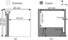
Figure 1. Layout of the single antenna element: (a) front view and (b) back view.

Figure 2. Geometric evolution of the single antenna element (ground plane).

Figure 3. The evolution of the simulated reflection coefficient curve according to the modifications.
Two different filters are integrated into the antenna element. The first is used to create a notched band at the WiMAX band (3.3–3.8 GHz) by introducing a half-wavelength (λ/2) RSRR etched in the top layer of the substrate with dimensions Lr × Wr, as shown in Fig. 4(a). The second is used to filter the higher frequencies of the band (5.15–5.925 GHz) by introducing a horizontal straight slot (LPF) on the back side of the antenna in the ground plane with a length of 21 mm and a wide of 0.5 mm as shown in Fig. 4(b).
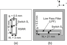
Figure 4. Layout of the reconfigurable antenna element: (a) top view and (b) back view.
The dimensions of RSRR and LPF that correspond to the filtering at 3.5 and 5.15 GHz are calculated using equations (1) and (2), respectively:
 \begin{equation}{f_{notche}} = {c \over {2 \times {L_{RSRR}} \times \sqrt {{\varepsilon _{eff}}} }},\end{equation}
 \begin{equation}{f_{filter}} = {c \over {2 \times {L_{LPF}} \times \sqrt {{\varepsilon _{eff}}} }},\end{equation}
 where ![]() ${L_{RSRR}} = 2 \times {l_r} + 2 \times {w_r} - {g_r}$ is the length of the RSRR at the desired notch frequency,
${L_{RSRR}} = 2 \times {l_r} + 2 \times {w_r} - {g_r}$ is the length of the RSRR at the desired notch frequency, ![]() ${L_{LPF}} = {w_l} + {g_l}$ is the length of the straight slot (LPF) at the desired filter frequency, and εeff is the effective dielectric constant of the substrate. The photograph of the realized prototype is shown in Fig. 5. Two switches S1 and S2 are used for frequency reconfiguration. The role of each switch is to enable/disable the filtering caused by the two mechanisms (RSRR and straight slot in the ground plane). The antenna has four different operating modes depending on the state of the two switches as shown in Table 1.
${L_{LPF}} = {w_l} + {g_l}$ is the length of the straight slot (LPF) at the desired filter frequency, and εeff is the effective dielectric constant of the substrate. The photograph of the realized prototype is shown in Fig. 5. Two switches S1 and S2 are used for frequency reconfiguration. The role of each switch is to enable/disable the filtering caused by the two mechanisms (RSRR and straight slot in the ground plane). The antenna has four different operating modes depending on the state of the two switches as shown in Table 1.

Figure 5. Realized antenna element prototype with ideal switches (case of notched band mode).
Table 1. Switches configuration for each mode

Operating modes of the proposed switchable single antenna element
In a first simulation phase, we modeled the switch with a conductive strip (ideal case) before proceeding with the implementation of the final prototype with PIN diodes. Both ON and OFF states are modeled in the simulation by the presence/absence of a conductive strip. The notch filter (RSRR) is activated when the switch S1 is in the ON state. The LPF is activated when switch S2 is in the OFF state. With this configuration, the antenna offers four different frequency operating modes summarized in Table 1. First, the initial wideband operating mode is obtained when S1 is in the OFF state and S2 is in the ON state (RSRR and LPF are disabled). The reflection coefficient curve shows that the working band at −10 dB is from 2.4 to 6 GHz for simulation and 2.55 to 6 GHz for measurement as shown in Fig. 6(a). Second, the notched band mode at 3.5 GHz (WiMAX band) is obtained when all switches are turned to ON state (RSRR is enabled, and LPF is disabled). From the S-parameters, which are shown in Fig. 6(b), we note that the simulated notched band is from 2.92 GHz to 4.06 GHz, whereas the measured band is from 3.1 to 3.86 GHz. The filtering property, with a good insertion loss, can be noticed at 3.49 GHz (greater than −1 dB), in simulation as well as in measurement. This notched band can be shifted by changing the electrical length of the RSRR as shown in Fig. 7(a). Third, the LPF mode is obtained when the switches (S1 and S2) are in the OFF state. The LPF mode gives a simulated reflection coefficient with bandwidth at −10 dB from 2.43 GHz to 4.69 GHz (relative bandwidth of 63.4%), where the measured bandwidth is from 2.68 GHz to 4.82 GHz (relative bandwidth of 58.07%) as shown in Fig. 6(c). The bandwidth can be reduced/increased by changing the electrical length of the horizontal slot as shown in Fig. 7(b). Finally, dual-band operation is obtained when S1 is in the ON state and S2 is in the OFF state. As shown in Fig. 6(d), the antenna has two frequency operating bands, the first from 2.4 to 2.85 GHz with a relative bandwidth of 17.7%, and the second from 3.9 to 4.7 GHz with a relative bandwidth of 17.9%. For measured results, the antenna operates in two bands of operation, 2.58–3.27 GHz (23.2%), and 3.86–4.58 GHz (17.06%). This last mode is used when WLAN and WiMAX bands are filtered simultaneously. We can note a good agreement between simulation and measurements. We only notice a small shift in the bands, which is essentially due to the quality of the manufacturing process.
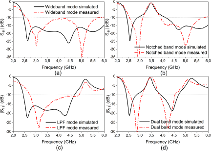
Figure 6. Measured and simulated reflection coefficient of the proposed reconfigurable single antenna element: (a) wideband mode, (b) notched band mode, (c) LPF mode, and (d) dual band mode.

Figure 7. Parametric studies on the reflection coefficient |S11|: (a) variation of Wr and (b) variation of Wl.
Two-element MIMO Antenna design
The reconfigurable MIMO antenna consists of two reconfigurable single antenna elements, arranged symmetrically relative to the y-axis and shares a common ground plane, with an edge-to-edge distance of 10 mm, as shown in Fig. 8. The MIMO antenna is fed by two 50 Ω SMA connectors. To improve the isolation between the two ports of the reconfigurable MIMO antenna, while keeping a compact structure, some modifications are introduced to the common ground plane as shown in Fig. 9, to obtain the final result. Due to the symmetry of the element S11 = S22 and S12 = S21. For the study, the mode without filtering with the largest bandwidth at −10 dB was chosen (mode wideband). We can note a clear improvement in the isolation inside the operating band of the antenna thanks to the modifications made to the ground plane. The superposed simulated scattering parameters of the MIMO antenna with and without isolation (configurations A and B) for the four operating states are presented in Fig. 10.

Figure 8. Layout of the reconfigurable two-element MIMO antenna: (a) front view and (b) back view.

Figure 9. |S|-parameters of the antenna for each configuration (wideband case).

Figure 10. Simulated |S|-parameters for the four operating modes with and without ground plane modifications: (a) wideband mode, (b) notched band mode, (c) LPF mode, and (d) dual band mode.
These simulation results demonstrate that with the modifications made to the common ground plane, the minimum isolation in the operating bands has been improved by at least 6 dB for both wideband and notched band modes.
For the other two modes, the minimum isolation has increased from 11 to 19 dB. We can also see that the lowest operating frequency returns to its initial value of 2.43 GHz (single antenna element) for all operating modes, as shown in Fig. 10. The switch states for each operating mode are listed in Table 2.
Table 2. Switches configuration for each mode of the proposed MIMO antenna

To better understand the physical operation of the antenna, a study of the surface current distributions has been carried out. Surface current distributions of the proposed reconfigurable MIMO antenna are observed in the four operating modes at 3.5 GHz (WiMAX) and 5.2 GHz (WLAN), to understand the operation of the two mechanisms of filtering (RSRR and LPF). Figure 11 shows the surface current densities for wideband mode, notched band mode, LPF mode, and dual-band mode, respectively. The surface current distributions for wideband mode (RSRR and LPF are disabled) are shown in Fig. 11(a) and (b) at 3.5 and 5.2 GHz, respectively.
For both frequencies, there is a current concentration on the feedline and the ground plane, which proves that the antenna works at these frequencies. In notched band mode at 3.5 GHz in Fig. 11(c), it can be noticed that a strong current distribution exists on the RSRR, which proves that the filtering mechanism (RSRR) at 3.5 GHz works.
We can also see that the current distribution is normally distributed between the feedline and the ground plane at 5.2 GHz, as shown in Fig. 11(d). For the LPF mode, there is a strong current concentration along the right slot in the ground plane at 5.2 GHz, as shown in Fig. 11(f). This concentration disappears at 3.5 GHz, as shown in Fig. 11(e), which proves that the horizontal slot in the ground plane filters the high frequencies of the working band (the LPF filtering mechanism is activated). Finally, in dual-band mode (RSRR and LPF are enabled), we can see a high current distribution on the RSRR in Fig. 11(g), and along the horizontal slot in Fig. 11(h), which confirms that the two filters operate simultaneously, respectively at 3.5 and 5.2 GHz. We also notice very good isolation between the two ports for all modes of operation, with very low surface current distribution on the second antenna element as shown in Fig. 11.

Figure 11. Surface current distribution: (a) wideband mode at 3.5 GHz, (b) wideband mode at 5.2 GHz, (c) notched band mode at 3.5 GHz, (d) notched band mode at 5.2 GHz, (e) LPF mode at 3.5 GHz, (f) LPF mode at 5.2 GHz, (g) dual band mode at 3.5 GHz, and (h) dual band mode at 5.2 GHz.
Implementation with Pin diodes
Figure 12 shows the layout of the reconfigurable MIMO antenna with the integration of real switches and the bias circuit necessary for the operation of the PIN diodes. The type of diode that is used is BAR50-02 V from the manufacturer’s Infineon. To take their effect into account in the simulations its S-parameters (s2p file) downloadable from the manufacturer’s website have been inserted in the antenna with CST Microwave Studio software. For the biasing of the diodes, decoupling capacitors of 100 pF and inductors (RF chokes) of 100 nH were used. Photographs of the realized prototype with PIN diodes are shown in Fig. 13.

Figure 12. Layout of the two-element reconfigurable MIMO antenna with PIN diodes and biasing circuit: (a) front view and (b) back view.

Figure 13. Photographs of the realized prototype with PIN diodes and bias circuit: (a) front view and (b) back view.
Experimental results and discussions
The simulated and measured S-parameters of the proposed reconfigurable MIMO antenna are shown in Fig. 14. For wideband mode, the simulated IBW is from 2.41 to 6 GHz, with a relative bandwidth of 84.4% and a minimum isolation of 17 dB between the two ports. It is also observed, that the measured IBW of the realized prototype is from 2.51 to 6 GHz with a relative bandwidth of 82.70%, and a minimum isolation of 18 dB over the operating band as shown in Fig. 14(a). A good result is obtained in notched band mode as shown in Fig. 14(b), with a notched band from 3.2 to 3.66 GHz at −10 dB to reject the WiMAX frequency band.
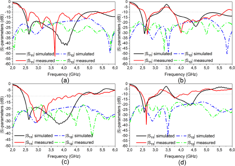
Figure 14. Simulated and measured |S|-parameters for all operating modes of the reconfigurable MIMO antenna: (a) wideband mode, (b) notched band mode, (c) LPF mode, and (d) dual band mode.
At the rejection band, the reflection coefficient has a peak of about −2 dB at 3.5 GHz, which signifies a strong and reliable rejection band. In LPF mode, as shown in Fig. 14(c), the simulated IBW is 2.4–4.7 GHz (relative bandwidth of 63.3%), and the measured is 2.61–4.53 GHz (relative bandwidth of 53.7%). The isolation is greater than 19 and 18 dB over the operating frequencies for simulation and measurement results, respectively. In dual-band mode, it is observed in Fig. 14(d) from simulated results that the antenna has two frequency operating bands: the first one is from 2.41 to 3.16 GHz (relative bandwidth of 29.18%), and the second one is from 3.64 to 4.7 GHz (relative bandwidth of 24.31%) with isolation greater than 23, and 18 dB for the two frequency bands, respectively. For the measured results of the manufactured prototype, the antenna supports two bands of operation 2.47–3.08 GHz (23.10%) and 3.59–4.34 GHz (19.09%). The isolation is greater than 20 and 18 dB for the two frequency bands, respectively. A good agreement is observed between simulation and measurement results for the different modes with small shifts of the bands, which are essentially due to manufacturing errors and electric wires.
During the measurement, port 1 was excited, whereas port 2 was terminated with a 50 Ω matched load as shown in Fig. 15. The measured and simulated radiation patterns (E-plane and H-plane) of the reconfigurable MIMO antenna at 3.5, 4.5, and 5.2 GHz for each mode are shown in Fig. 16. The measurement results show that the proposed antenna has an omnidirectional radiation pattern in the H-plane and bidirectional radiation in the E-plane. Table 3 gives the simulated and measured realized gain for the different states of the proposed reconfigurable MIMO antenna at different operating frequencies. A good agreement is observed between simulation and measurement results.

Figure 15. Radiation pattern measurement setup (anechoic chamber).

Figure 16. Simulated and measured radiation patterns: (a) wideband mode at 5.2 GHz, (b) notched band mode at 5.2 GHz, (c) wideband mode at 3.5 GHz, (d) LPF mode at 3.5 GHz, (e) LPF mode at 4.5 GHz, and (f) dual band mode at 4.5 GHz.
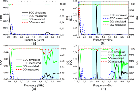
Figure 17. Simulated and measured ECC and DG results of the proposed reconfigurable MIMO antenna: (a) wideband mode, (b) notched band, (c) LPF mode, and (d) dual band mode.
Table 3. Simulated and measured realized gain at different frequencies for all operating modes

Diversity performance
To evaluate the diversity performance of the proposed reconfigurable MIMO antenna, parameters were calculated and analyzed from the simulated and measured S-parameters [Reference Sharawi27]. The results obtained were then compared with other work recently reported in the literature.
Envelope Correlation Coefficient (ECC)
The ECC is used to determine the correlation between the various antenna elements in a MIMO antenna system. In practice, ECC values should be less than 0.5. It is possible to calculate it from the S-parameters [Reference Sharawi27], using equation (3) or from the far-field radiation using equation (4). The simulated and measured ECC using S-parameters of the proposed antenna is illustrated in Fig. 17. A good agreement between simulations and measurements is obtained. It is less than 0.008 in the whole operating band for the various modes which means a very low correlation between the two antenna elements. The ECC value increases at filtered frequencies (WiMAX/WLAN) while maintaining a good value as shown in Fig. 17(b–d). This indicates a good decoupling between the two ports even inside the filtered bands:
 \begin{equation}{\rm{ECC}} = {{{{\left| {{\rm{S}}_{11}^{\rm{*}}{{\rm{S}}_{12}} + {\rm{S}}_{21}^{\rm{*}}{{\rm{S}}_{22}}} \right|}^2}} \over {\left( {1 - \left( {{{\left| {{{\rm{S}}_{11}}} \right|}^2} + {{\left| {{{\rm{S}}_{21}}} \right|}^2}} \right)} \right)\!\left( {1 - \left( {{{\left| {{{\rm{S}}_{22}}} \right|}^2} + {{\left| {{{\rm{S}}_{12}}} \right|}^2}} \right)} \right)}},\end{equation}
 \begin{equation}ECC = {{{{\left| {\smallint {\smallint _{4{{\pi }}}}\left[ {\overrightarrow {{F_1}} \left( {\theta ,\varphi } \right).\overrightarrow {{F_2}} \left( {\theta ,\varphi } \right)} \right]{\rm{d}}\Omega {\ }} \right|}^2}} \over {\smallint {\smallint _{4{{\pi }}}}{{\left| {\overrightarrow {{F_1}} \left( {\theta ,\varphi } \right)} \right|}^2}{\rm{d}}\Omega \;\smallint {\smallint _{4{{\pi }}}}{{\left| {\overrightarrow {{F_2}} \left( {\theta ,\varphi } \right)} \right|}^2}{\rm{d}}\Omega {\ }}}.\end{equation}
Diversity Gain (DG)
Figure 17 shows simulated and measured DG for the four operating modes. It can be calculated using the following equation [Reference Kumar, Ansari, Kanaujia, Kishor and Kumar17]:
 \begin{equation}{\textrm{DG}} = 10\sqrt {1 - {{\left( {0.99{\textrm{ECC}}} \right)}^2}} .\end{equation}
It can be observed that the DG of the MIMO antenna is greater than 9.9 for the four modes of operation. This value changes only in the filtering bands related to the WiMAX and WLAN bands as shown in Fig. 17(b–d). These results validate the good diversity performances of the MIMO structure. Table 4 gives the simulated and measured ECC and DG for the different operating modes of the antenna.
Table 4. Simulated and measured values of ECC and DG for each mode

Comparison with recent work
The proposed two-element reconfigurable MIMO antenna is compared to other recently published MIMO antenna structures. The comparison is presented in Table 5 based on several parameters. It can be easily observed from the table that the proposed design approach has a more flexible frequency profile, good isolation, low complexity, and low ECC value, what makes this structure very interesting.
Table 5. Comparison between performances of the proposed MIMO antenna and other reported works
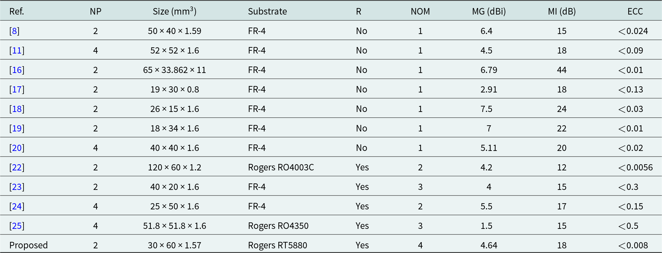
NP = number of ports, R = reconfigurable, NOM = number of frequency operating modes, MG = maximum gain, MI = minimum isolation.
Conclusion
In this paper, a compact reconfigurable two-element MIMO antenna is presented and its performances are discussed. The MIMO structure is endowed with two filtering mechanisms. By using PIN diodes to enable/disable each filter, the antenna provides four different operating modes. Isolation greater than 18 dB is achieved for the four operating modes. Additionally, diversity performance is calculated and compared to recently reported designs that demonstrate the advantages of the proposed concept. The ECC of the proposed antenna is less than 0.008 with a high DG (DG > 9.99) for the four operating modes. All the results obtained from the study of the structure indicate that the MIMO antenna is suitable for cognitive radio and 5G NR sub-6 GHz applications.
Competing interests
None declared.

Yahia Benghanem received his Master degree in Aeronautical Engineering from the High School of Aeronautical Techniques of Dar-El-Beida, Algeria, in 2018 and started his doctoral studies in the field of Antennas and Wave propagation at the Institute of Aeronautics and Spatial Studies, University of Blida, Algeria in 2019. His current research interests include antenna design, reconfigurable antennas, MIMO antenna systems, and wireless communication.

Ali Mansoul received his engineering degree in Electronics from the University of Jijel, Algeria, in 2006, his M.Sc. degree in Telecommunications from Polytechnic School of Bordj El Bahri, Algiers, Algeria, in 2010 and, his PhD degree in Telecommunications from the National Polytechnic school of Algiers, in 2016. Currently, he is a researcher director and Head of the antennas & propagation Group at Centre de Developpement des Technologies Avancees (CDTA), in Baba Hassen, Algiers, Algeria. His research interests include antennas design, reconfigurable antennas, metamaterials, RF circuits, MIMO systems, and wireless communication.

Lila Mouffok received her Engineering degree in Electronics from the University of Blida, Algeria, in 2008, her M.Sc. in Electronics and Communication Systems from University of Pierre and Marie Curie, Paris, France, in 2009, and her Ph.D. degrees from Telecom ParisTech, Paris, France, in 2013. She joined the Centre de Developpement des Technologies Avancees (CDTA) in Baba Hassen, Algiers, Algeria, as Researcher. Since October 2015, she has been an Associate Professor at Institute of Aeronautics and Spatial Studies, University of Blida, Algeria. Her research interests include antenna design, MIMO systems, metamaterials, wireless communication, propagation channel.


