1 Introduction
The current demand for strong yet stiff and lightweight structural components in transportation vehicles and civil structures has been rapidly increasing primarily due to the common objective of energy saving to reduce the environmental and economic impact. Moreover, bioengineering and biomechanical applications demand production of tailored components with optimal specific stiffness and strength, similar to natural materials and living tissues. To this end, fiber reinforced polymers (FRPs) offer several advantages in the design of modern structures. Nevertheless, the low hardness of FRPs restricts their use in machine elements and structural components with inevitable demanding contacts such as bearings, joints, gears, etc. In quest of optimal design, complicated parts, consisting of multi-material domains, are recently designed and used in high-end applications such as aerospace, automotive, sports etc.
Conventionally mechanical locking with bolted and riveted connections is favored, avoiding bonded interfaces wherever possible to combine multi-material parts. The reason for the latter is the difficulty in robust characterization of adhesively bonded interfaces and the number of parameters that affect the durability of the resulted joints such as material characteristics (stiffness, thermal expansion, surface energy, etc.), mechanical and chemical surface treatment, surface purification, curing conditions, etc. (Ikegami et al. Reference Ikegami, Fujii, Kawagoe, Kyogoku, Motoie, Nohno, Sugibayashi and Yoshida1996; Bland, Kinloch and Watts Reference Bland, Kinloch and Watts2013) . The variety of materials and mentioned parameters provides a wide range of tensile and shear strengths for adhesively bonded joints from a couple to 100 MPa, while fracture toughness can vary from ten to a couple of thousand J/m2 depending also on fracture mode and mode mixity (Ikegami et al. Reference Ikegami, Fujii, Kawagoe, Kyogoku, Motoie, Nohno, Sugibayashi and Yoshida1996; Sørensen, Goutianos and Jacobsen Reference Sørensen, Goutianos and Jacobsen2009; Sarrado et al. Reference Sarrado, Turon, Costa and Renart2016) . While the in-plane and out-of-plane fracture toughness is reported always higher than the corresponding mode I (Chaves et al. Reference Chaves, da Silva, de Moura, Dillard and Esteves2014 & Refs. therein), shear strength is reported higher, lower or of the same range with the analogous tensile strength (Ikegami et al. Reference Ikegami, Fujii, Kawagoe, Kyogoku, Motoie, Nohno, Sugibayashi and Yoshida1996; Sørensen, Goutianos and Jacobsen Reference Sørensen, Goutianos and Jacobsen2009; Sarrado et al. Reference Sarrado, Turon, Costa and Renart2016; Kim, Naito and Oguma Reference Kim, Naito and Oguma2017).
FRPs can be jointed with metallic, ceramic or other polymeric pieces to form multi-material parts. The FRPs may be pre-cured before the joint is created necessitating mechanical (bolting or riveting) or adhesively bonded joint or they can be cured directly on the counterpart, as it is done for example in the production of sandwich beams or GLARE™ (Abouhamzeh, Sinke and Benedictus Reference Abouhamzeh, Sinke and Benedictus2015). The latter process has the advantage of the single fabrication step; however, it requires thorough preparation and includes potential effect of residual stresses as well as lower modularity. Nevertheless, smart design can lead to elimination of stress concentrators which coupled with geometry optimization, may result in higher weight gain.
One of the most notable successful efforts in integrating metal/carbon fiber reinforced polymer (CFRP) multi-material component on high-end application, is found in the development of a gearbox casing that was introduced in Formula-1 (F1) in the mid-90s by John Barnard (Wright Reference Wright2001). This example shows the transition from ultra-light metals, such as magnesium found on the initial segmentation of the casing, to the introduction of CFRP and later to multi-material components. There, trials on bonding the CFRP with the metallic part to house the bearing revealed damage issues related to the thermal expansion mismatch. These issues may occur, not only as a result of residual stresses but also as stresses introduced during service temperatures, that for the described case are on the range of 100 °C, considering ambient and the steady working conditions. Due to these issues, the most recent designs avoid bonding in critical parts and favor mechanical locking in order to reduce the risk.

Figure 1. (Left): Exoskeleton concept & loads at extreme case, adapted from www.relab.ethz.ch and varileg.ch. (Right): Hip–pelvis component advanced design; initial input.
2 Scope
The purpose of this study is to investigate the feasibility of a multi-material FRP–aluminum structural component of a robotic exoskeleton. The investigation of the concept involves durability analysis of the structure focusing on the local stress state of the created polymer–aluminum interface. Parameters such as functionality, materials, processing and geometry are taken into consideration. The durability of the resulting interface is evaluated by means of interface strength and fracture toughness. To conduct the feasibility analysis, pertinent systematic and parametric Finite Element (FE) simulations, involving cohesive contact modeling, are established to optimize the design of the component. The design optimization process is described by sequential iterations where the FE models’ results are compared with the experimentally acquired strength and fracture toughness. Two types of surfaces are considered experimentally: plain and a sandblasted (SB) one, to investigate the effect of the latter in the anticipated durability.
3 Concept definition and optimization routine
3.1 Component characteristics and definition of constraints
The work reported herein refers to the design of an element intended to replace an existing hip–pelvis bracing component of the VariLeg lower limb exoskeleton (see Figure 1 (Left)), developed by pd|z and RELab, ETHZ (Schrade et al. Reference Schrade, Dätwyler, Stücheli, Studer, Türk, Meboldt and Gassert2018). This hip–pelvis component has to support the weight of the patient, house the gait actuation motor and connect the two leg supports with each other. Thus, it is the core of the exoskeleton that is subjected to combined bending and torque moments as it connects the moving parts of the exoskeleton with the human hip and pelvis.
The overall designing concept, apart from creating a functional part, focused on maximizing the weight reduction, on minimizing the number of required components and fabrication steps and, most importantly, on being patient specific with geometry, tailored to the body of each individual (Kussmaul et al. Reference Kussmaul, Biedermann, Pappas, Jónasson, Winiger, Zogg, Türk, Meboldt and Ermanni2019). To this end, a CFRP-based design was chosen as the main carrier of the loads. However, metallic regions were inevitable in order to house the actuation motors. Conventional joining techniques such as riveting or bolting were excluded from the design process in order to avoid stress concentrations and potential damage localization in the CFRP section. Thus, an aluminum/CFRP bonded region was present. Curing of the CFRP section directly on the aluminum one, provides a significant gain in the overall process, since the part can be fabricated in a single step, instead of employing an additional stage to adhere the two components. A post curing joining stage would also require a complementary step to machine the CFRP section in order to have a perfect match on the adhered surfaces. For all the aforementioned reasons, it was set as a primary objective to preserve the single-step curing technique throughout the design process.
The final component resulted from an innovative design, developed in collaboration with pd|z and CMASLab ETH Zurich (Kussmaul et al. Reference Kussmaul, Biedermann, Pappas, Jónasson, Winiger, Zogg, Türk, Meboldt and Ermanni2019). The manufacturing concept comprises manual stacking of cross-ply woven prepreg CFRP layers in a quasi-isotropic layup, on a polymer core/mold created by additive manufacturing and the two symmetric aluminum components/housings of the actuation motors (see Figure 1(Right)). The additive manufactured core facilitates the design of a patient specific and ergonomic component. Opting for high quality material, the prepreg CFRP is cured using standard autoclave procedures. Another key advantage of the 3D printed inner polymer core is that its major part is discarded after the curing cycle’s end. This process allows for a lightweight and at the same time patient specific part to be created, improving the experience and adaptation time of the patient. Further details on the development of the inner core and global design framework can be found in Kussmaul et al. (Reference Kussmaul, Biedermann, Pappas, Jónasson, Winiger, Zogg, Türk, Meboldt and Ermanni2019).
3.2 Optimization approach
The work presented herein deals with the optimization of the durability of a multi-material CFRP–metallic structural component based on the stress state that occurs on the formed interface. The functionality (i.e. motion actuation) and the expected service loads are design constraints that cannot be altered or modified while the global/or local geometry, the choice of materials, the processing and its effects are features that control the optimality of the durability. By all means, maximal weight gain and number of processing steps should be maintained throughout this process. A schematic of the optimization method map is illustrated in Figure 2. The optimal solution sought is a structure with the lowest possible tractions at the interface given the chosen material system, loading conditions and global geometry. By comparing the stress results of the simulations with the experimental strengths allows defining a safety factor. To assess the extent of safety, the experimental toughness of the interface is also taken into account as follows: a low toughness interface necessitates a higher stress-based safety factor as opposed to a high toughness one.
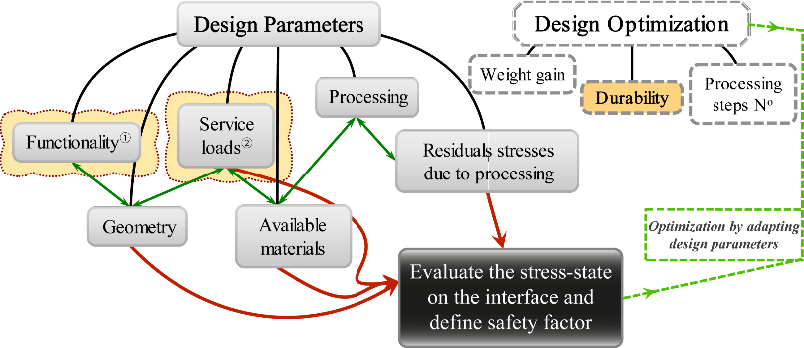
Figure 2. Design optimization approach based on the design parameters. Functionality
![]() $^{\unicode[STIX]{x2460}}$
and service loads
$^{\unicode[STIX]{x2460}}$
and service loads
![]() $^{\unicode[STIX]{x2461}}$
are set constraints.
$^{\unicode[STIX]{x2461}}$
are set constraints.
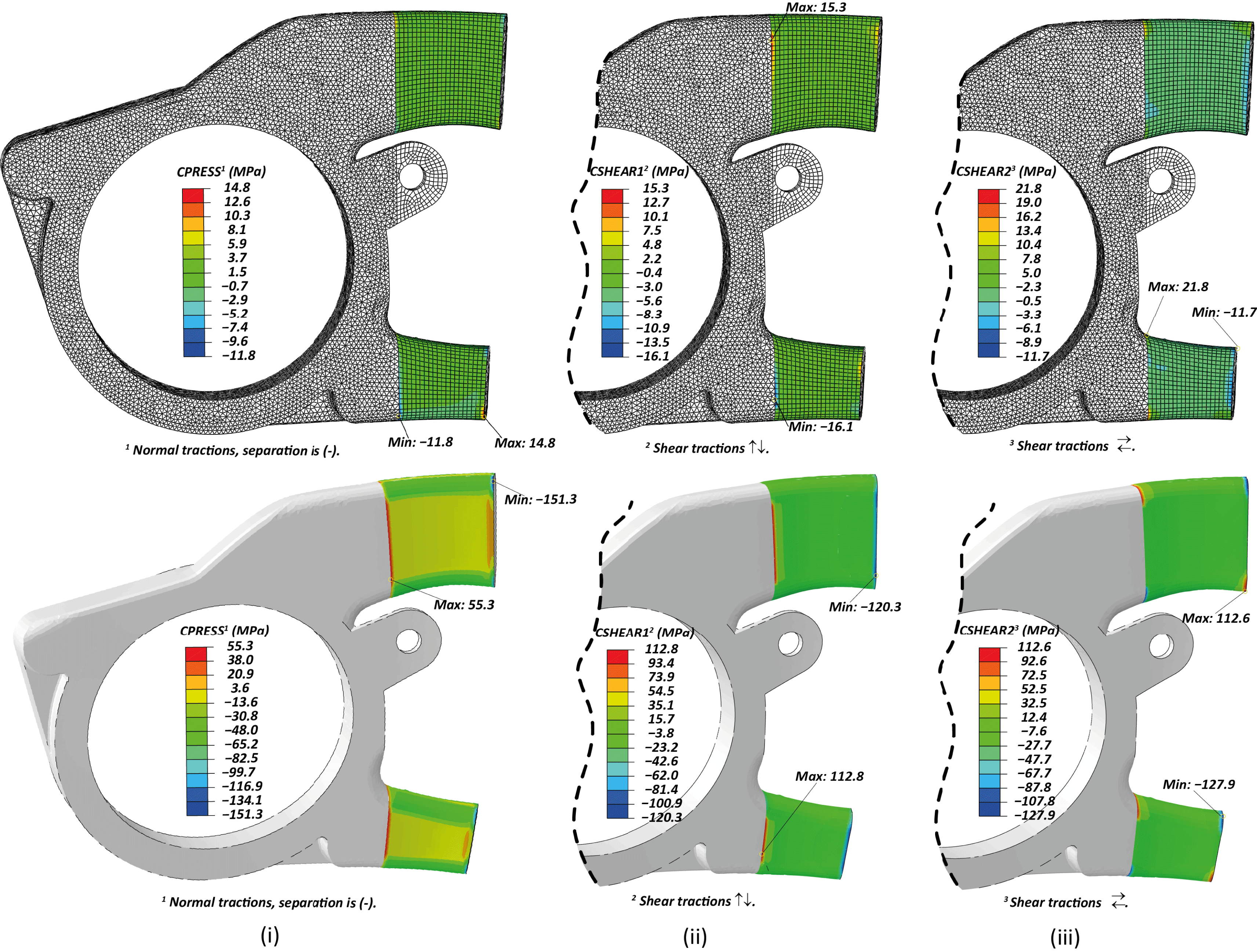
Figure 3. FE results of cohesive contact stress profile: (i) Normal; negative is in tension, (ii) Shear Vertical, (iii) Shear Horizontal. (Top): Iteration 1a. (Bottom): Iteration 1b.
4 Methods
4.1 Numerical scheme
In order to evaluate the stresses developed in the bonded aluminum–CFRP region, pertinent numerical models are built-in Abaqus Standard v6.12 implementing the built-in contact interaction algorithm (Dassault Systèmes © 2012). A representative geometry tailored to an 85 kg weighted patient is implemented in the FE models, which is considered an extreme for a paraplegic case. The symmetric half is only considered for these models to minimize the numerical processing time during the iterative optimization. The aluminum part is discretized using 3D linear tetrahedral and hexahedral elements (Abaqus C3D4 and C3D8 respectively, see also Figure 3 (Top)) and the CFRP structure with linear quadrilateral, shell elements with reduced integration (Abaqus S4R) and an assigned thickness of 2 mm. The complete model comprises approximately 430,000 elements. The two parts are connected using contact pairs with cohesive interaction properties in the bonded surfaces. Particular attention is applied on the meshing scheme to balance the need for mesh refinement and reasonable processing time. Thus, seeding of the geometry is performed in a way that provides coincidence for the vast majority of the nodes involved in the contact pairs and improve the robustness of the surface to surface discretization. The traction separation relation’s linear stiffness coefficients are set to default penalty values (10 × the stiffness of the involving elements). Initially, for the design optimization stages, no damage parameters are implemented, since the durability of the interface is primarily evaluated with a strength criterion, without considering damage tolerance based design at this stage.
Typical linear elastic isotropic material properties are considered for the aluminum region, with a Young’s modulus
![]() $E_{\text{Al}}=70~\text{GPa}$
and a Poisson’s ratio
$E_{\text{Al}}=70~\text{GPa}$
and a Poisson’s ratio
![]() $\unicode[STIX]{x1D708}_{\text{Al}}=0.33$
. Quasi-isotropic (or, quasi-iso) laminate (
$\unicode[STIX]{x1D708}_{\text{Al}}=0.33$
. Quasi-isotropic (or, quasi-iso) laminate (
![]() $[0/90,\pm 45]_{\text{xs}}$
) orthotropic properties are considered for the composite shell region, based on the chosen CFRP material which is a woven cross-ply with cured-ply thickness ∼0.2 mm (SIGRA TEX PREPREG CE 8201-200-45S). The resulted values, calculated by the single-ply properties and Classical Laminate Theory (CLT), are: elastic moduli,
$[0/90,\pm 45]_{\text{xs}}$
) orthotropic properties are considered for the composite shell region, based on the chosen CFRP material which is a woven cross-ply with cured-ply thickness ∼0.2 mm (SIGRA TEX PREPREG CE 8201-200-45S). The resulted values, calculated by the single-ply properties and Classical Laminate Theory (CLT), are: elastic moduli,
![]() $E_{1},E_{2}\simeq 42~\text{GPa}$
, shear moduli,
$E_{1},E_{2}\simeq 42~\text{GPa}$
, shear moduli,
![]() $G_{12}\simeq 17~\text{GPa}$
,
$G_{12}\simeq 17~\text{GPa}$
,
![]() $G_{13},G_{23}\simeq 5~\text{GPa}$
and Poisson ratio,
$G_{13},G_{23}\simeq 5~\text{GPa}$
and Poisson ratio,
![]() $\unicode[STIX]{x1D708}_{12}\simeq 0.31$
. These values were considered a good approximation of the final layup that resulted from a complex draping optimization (for details see Kussmaul et al.
Reference Kussmaul, Biedermann, Pappas, Jónasson, Winiger, Zogg, Türk, Meboldt and Ermanni2019).
$\unicode[STIX]{x1D708}_{12}\simeq 0.31$
. These values were considered a good approximation of the final layup that resulted from a complex draping optimization (for details see Kussmaul et al.
Reference Kussmaul, Biedermann, Pappas, Jónasson, Winiger, Zogg, Türk, Meboldt and Ermanni2019).
An effective torque,
![]() $T_{\text{eff}}$
, and a normal force,
$T_{\text{eff}}$
, and a normal force,
![]() $P_{\text{eff}}$
(causing moment
$P_{\text{eff}}$
(causing moment
![]() $M_{\text{eff}}$
), of 245 Nm and 300 N respectively, are applied in the center of hip actuation motor’s position (Figure 1 (Right)). These loads correspond to the extreme ones developed during the stair-climbing and were measured in situ, for an 85 kg patient, by the Laboratory for Mechanical Systems Engineering, EMPA, Dübendorf, Switzerland (Kussmaul et al.
Reference Kussmaul, Biedermann, Pappas, Jónasson, Winiger, Zogg, Türk, Meboldt and Ermanni2019). Fixed boundary conditions, both in displacement and rotation are implemented on the symmetry plane (see Figure 1 (Right)).
$M_{\text{eff}}$
), of 245 Nm and 300 N respectively, are applied in the center of hip actuation motor’s position (Figure 1 (Right)). These loads correspond to the extreme ones developed during the stair-climbing and were measured in situ, for an 85 kg patient, by the Laboratory for Mechanical Systems Engineering, EMPA, Dübendorf, Switzerland (Kussmaul et al.
Reference Kussmaul, Biedermann, Pappas, Jónasson, Winiger, Zogg, Türk, Meboldt and Ermanni2019). Fixed boundary conditions, both in displacement and rotation are implemented on the symmetry plane (see Figure 1 (Right)).
The stress state on the jointed interfaces is influenced not only by the service loads but also by the residual stresses on the interface. An important thermal expansion coefficient mismatch (about one order of magnitude) between aluminum and CFRP is present, originating from the minimal thermal expansion coefficient of the neat carbon fibers. In detail the thermal expansion coefficient of aluminum is
![]() $\unicode[STIX]{x1D6FC}_{\text{Al}}\simeq 24\times 10^{-6}~\text{K}^{-1}$
, while the estimated ones for a quasi-iso CFRP are
$\unicode[STIX]{x1D6FC}_{\text{Al}}\simeq 24\times 10^{-6}~\text{K}^{-1}$
, while the estimated ones for a quasi-iso CFRP are
![]() $\unicode[STIX]{x1D6FC}_{11},\unicode[STIX]{x1D6FC}_{22}\simeq 2.2\times 10^{-6}~\text{K}^{-1}$
and
$\unicode[STIX]{x1D6FC}_{11},\unicode[STIX]{x1D6FC}_{22}\simeq 2.2\times 10^{-6}~\text{K}^{-1}$
and
![]() $\unicode[STIX]{x1D6FC}_{33}\simeq 5.2\times 10^{-6}~\text{K}^{-1}$
(Daniel and Ishai Reference Daniel and Ishai1994). To evaluate the effect of this mismatch, a homogeneous temperature field was used in the numerical model with a gradient between the initial and the first step equal to the cool-down temperature descent, by implementing the corresponding thermal expansion coefficients for each used material, in order to simulate the thermal shrinkage of the part after curing. Thus, the calculated stress state at the end of the each iteration should correspond to the actual state condition of the part in service during the extreme loading.
$\unicode[STIX]{x1D6FC}_{33}\simeq 5.2\times 10^{-6}~\text{K}^{-1}$
(Daniel and Ishai Reference Daniel and Ishai1994). To evaluate the effect of this mismatch, a homogeneous temperature field was used in the numerical model with a gradient between the initial and the first step equal to the cool-down temperature descent, by implementing the corresponding thermal expansion coefficients for each used material, in order to simulate the thermal shrinkage of the part after curing. Thus, the calculated stress state at the end of the each iteration should correspond to the actual state condition of the part in service during the extreme loading.
Guided by the results and the revealed significance of each affecting parameter, the described model was solved in successive iterations by optimizing the local geometry and considering relevant modification of the interface to minimize the resulting normal and in-plane shear tractions on the bonded surfaces, pursuing improved durability.
4.2 Interface/surface modification & experimental scheme
To evaluate the durability safety factor of the designed bonded interface on the structure, the strength and toughness of bonded joint have to be known. However, as it has been already mentioned, strength and toughness of polymer–metallic interfaces vary significantly and depend on various parameters thus, it is difficult to characterize. Aluminum oxides are expected to form immediately after the exposure of pure aluminum to the ambient oxygen, thus they are expected to coat any aluminum surface completely with a film of a few nanometers, within 5–10 minutes (Krueger and Pollack Reference Krueger and Pollack1972; Dumas et al. Reference Dumas, Dubarry-Barbe, Rivière, Levy and Corset1983). Targeted tailoring of those oxides appears to have improvement on the adhesive properties of aluminum–polymeric interfaces. In detail, considerable toughening is obtained when a purer form of those oxides is achieved, by chemical treatment such as chromic-acid etching (Dickie et al. Reference Dickie, Haack, Jethwa, Kinloch and Watts1998), and when anodization is implemented (Bland, Kinloch and Watts, Reference Bland, Kinloch and Watts2013). The former one reduces the amount of carbon in the oxide coat, while the latter provides a uniform coating on the aluminum surface with a porous finishing on the scale of 50 nm (Edwards Reference Edwards1997). A controlled anodizing process has the advantage of high reproducibility. Nevertheless, anodize crazing may appear after the part is exposed to temperatures higher than 80 °C due to the thermal expansion coefficients mismatch of the anodic layer and the neat aluminum (Edwards Reference Edwards1997), the effect of which is unknown on polymeric joints.
As explained earlier, an important objective of the investigated design is to fulfill bonding and curing process in a single step, thus, to avoid anodize crazing due to the curing temperatures anodization was not considered. In addition, acid etching due to the low reproducibility of the result and the handling process was excluded. In this work, two types of aluminum surfaces are considered for the bonded region: (i) typical ones obtained by extrusion, rolling or a fine milling process (herein called plain) and (ii) grit-blasted (or sandblasted, SB). For the latter case, grit removal with abundant water and degreasing with alcohol and finally pure acetone was followed, while for the former one just the last two steps were needed, before laying the CFRP layers.
In order to measure the strength and toughness of the bonded joint an experimental characterization process is followed. To evaluate the shear strength of the interface double shear lap (DSL) specimens were fabricated and tested, following the guidelines of the ASTM standard (ASTM Standard D3528 – 96 2016). Double cantilever beam specimens were fabricated and tested based on the ISO standard (ISO 25217 2009) to measure the mode I fracture toughness. The mode II toughness was measured using the four point bend, end notched flexure (4ENF) configuration (Martin and Davidson Reference Martin and Davidson1999). As it will be discussed later, an adherent epoxy layer promotes the durability of the joint, thus the critical interface to evaluate is of aluminum-epoxy.
5 Results and discussion
5.1 Numerical modeling
As described already, the problem has been investigated through an iterative optimization process. Thus, guided by the results at the end of each step/iteration, the local design and concept are re-evaluated. These results and evaluation analysis are reported in this section.
5.1.1 1st Iteration
An initial design of the multi-material component was formed, guided mainly by the geometric and functional constraints. The resulted stress state on the aluminum–CFRP interface, of the first numerical iteration is illustrated in Figure 3. Initially, only the aforementioned extreme service loads were implemented and the normal and shear stresses developed were essentially low (±5 MPa) with some peaks of ∼15 MPa (Figure 3 (Top) – Iteration 1a). It should be noted that since the contact algorithm is employed, the normal tractions are referred to as contact pressure (Abaqus CPESS), thus they are reported negative (
![]() $-$
) when the surfaces tend to separate. Such values are expected to be on the safe side according to the literature (Ikegami et al.
Reference Ikegami, Fujii, Kawagoe, Kyogoku, Motoie, Nohno, Sugibayashi and Yoshida1996). However, when a thermal step of
$-$
) when the surfaces tend to separate. Such values are expected to be on the safe side according to the literature (Ikegami et al.
Reference Ikegami, Fujii, Kawagoe, Kyogoku, Motoie, Nohno, Sugibayashi and Yoshida1996). However, when a thermal step of
![]() $\unicode[STIX]{x0394}T=-80\,^{\circ }\text{C}$
(accounting for curing at 100 °C, corresponding to the nominal temperature recommended (SGL epo GmbH 2010)) was included in the model, the stresses were one order of magnitude higher than the previous sub-step (Figure 3 (Bottom) – Iteration 1b).
$\unicode[STIX]{x0394}T=-80\,^{\circ }\text{C}$
(accounting for curing at 100 °C, corresponding to the nominal temperature recommended (SGL epo GmbH 2010)) was included in the model, the stresses were one order of magnitude higher than the previous sub-step (Figure 3 (Bottom) – Iteration 1b).
These preliminary numerical results show that the thermal stresses, due to the cool-down step, account for more than 85% of the interface tractions at the extreme load conditions, especially in the normal to the surfaces direction. Therefore, the residual stresses play a critical role on the durability of the structure and should definitely not be excluded from the analysis. The reason for those high tractions is the important thermal expansion coefficient mismatch, since the one of the CFRP (in-plane) is one order of magnitude lower than that of aluminum. The calculated tractions on the interfaces of the initial design are comparable with the strengths of an ordinary epoxy (Fiedler et al. Reference Fiedler, Hojo, Ochiai, Schulte and Ando2001) or even the interlaminar shear strength of the CFRP material (SGL epo GmbH 2010), with some high peaks observed on the transition points, as depicted in Figure 3 (Bottom) – Iteration 1b. Thus, the designed geometry is expected to fail right after the end of autoclave’s cool-down step, and for this reason further adjustments were processed.
5.1.2 2nd Iteration
The results of the first iteration revealed that the high interface tractions originate from the higher shrinkage of the aluminum part against the CFRP shell, at the end of the curing process and room temperature. It is important to notice that the latter effect is exacerbated from the comparable moduli of CFRP and aluminum; thus the CFRP shell structure ‘resists’ on adapting to the aluminum domain. To reduce the later effect an additional compliant layer of pure epoxy is considered in the FE model. To preserve the production of the multi-material part in a single step, the epoxy is modeled to correspond to the Gurit SA-80 (Gurit SP™ 2017) prepreg epoxy adhesive film (
![]() $275~\text{g}/\text{m}^{2}$
), toughened with glass fibers (9% in mass), the use of which preserves all the characteristics of the fabrication concept. This epoxy film is optimized for sandwich structures and it can be laid on the aluminum surface before the CFRP layers, while the curing cycle is compatible with the one of the CFRP prepreg. In-house trials show that the cured-ply thickness of the film is ∼0.21 mm when it is used in between non-porous media.
$275~\text{g}/\text{m}^{2}$
), toughened with glass fibers (9% in mass), the use of which preserves all the characteristics of the fabrication concept. This epoxy film is optimized for sandwich structures and it can be laid on the aluminum surface before the CFRP layers, while the curing cycle is compatible with the one of the CFRP prepreg. In-house trials show that the cured-ply thickness of the film is ∼0.21 mm when it is used in between non-porous media.
The FE model was reconstructed to include the resin layers which were modeled as isotropic solid with
![]() $E_{Ep}=2.50~\text{GPa}$
,
$E_{Ep}=2.50~\text{GPa}$
,
![]() $\unicode[STIX]{x1D708}_{Ep}=0.33$
and
$\unicode[STIX]{x1D708}_{Ep}=0.33$
and
![]() $\unicode[STIX]{x1D6FC}_{Ep}\simeq 55\times 10^{-6}~\text{K}^{-1}$
(the Young’s modulus is provided by Gurit SP™ and the rest are typical values (Daniel and Ishai Reference Daniel and Ishai1994)).
$\unicode[STIX]{x1D6FC}_{Ep}\simeq 55\times 10^{-6}~\text{K}^{-1}$
(the Young’s modulus is provided by Gurit SP™ and the rest are typical values (Daniel and Ishai Reference Daniel and Ishai1994)).
The results of the FE model with one layer showed an important reduction of the interface tractions, nevertheless, two layers of epoxy were necessary to obtain a reduction of the maximum shear tractions at
![]() ${\sim}\frac{1}{5}$
and
${\sim}\frac{1}{5}$
and
![]() ${\sim}\frac{1}{3}$
on the normal ones compared to iteration 1b. Yet, the expected interface tractions after the curing process and under the extreme loading conditions are still high (>25 MPa) (see Figure 4 (Right)).
${\sim}\frac{1}{3}$
on the normal ones compared to iteration 1b. Yet, the expected interface tractions after the curing process and under the extreme loading conditions are still high (>25 MPa) (see Figure 4 (Right)).
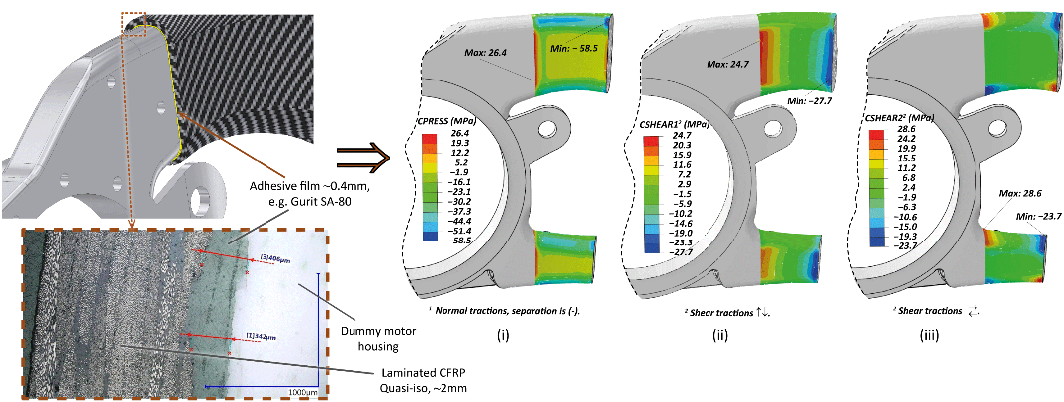
Figure 4. Iteration 2 with epoxy layer ∼0.4 mm. (Left): 3D CAD and micrograph of sectioned dummy/prototype part. (Right): FE results of cohesive contact stress profile: (i) Normal; negative is in tension, (ii) Shear Vertical, (iii) Shear Horizontal.
The numerical models were relaunched including damage behavior in the contact properties, in order to locate the regions that are most critical for failure. A quadratic traction criterion was employed, assuming an
![]() $\frac{1}{1}$
ratio between the maximum nominal normal and shear stress. These values are typical ones found in the literature and the references cited herein (Ikegami et al.
Reference Ikegami, Fujii, Kawagoe, Kyogoku, Motoie, Nohno, Sugibayashi and Yoshida1996; Sørensen, Goutianos and Jacobsen Reference Sørensen, Goutianos and Jacobsen2009; Sarrado et al.
Reference Sarrado, Turon, Costa and Renart2016; etc.) for equivalent bonded interfaces (
$\frac{1}{1}$
ratio between the maximum nominal normal and shear stress. These values are typical ones found in the literature and the references cited herein (Ikegami et al.
Reference Ikegami, Fujii, Kawagoe, Kyogoku, Motoie, Nohno, Sugibayashi and Yoshida1996; Sørensen, Goutianos and Jacobsen Reference Sørensen, Goutianos and Jacobsen2009; Sarrado et al.
Reference Sarrado, Turon, Costa and Renart2016; etc.) for equivalent bonded interfaces (
![]() $\frac{2}{1}$
to
$\frac{2}{1}$
to
![]() $\frac{1}{2}$
). With the assumed ratio, the most critical, prone to damage initiation region, appears to be on the upper branch of the aluminum motor housing (see Figure 5), where both opening and shear tractions escalate both, not only due to the residual stresses, but also due to the torsional moments and bending forces that induce shear tractions on that region.
$\frac{1}{2}$
). With the assumed ratio, the most critical, prone to damage initiation region, appears to be on the upper branch of the aluminum motor housing (see Figure 5), where both opening and shear tractions escalate both, not only due to the residual stresses, but also due to the torsional moments and bending forces that induce shear tractions on that region.
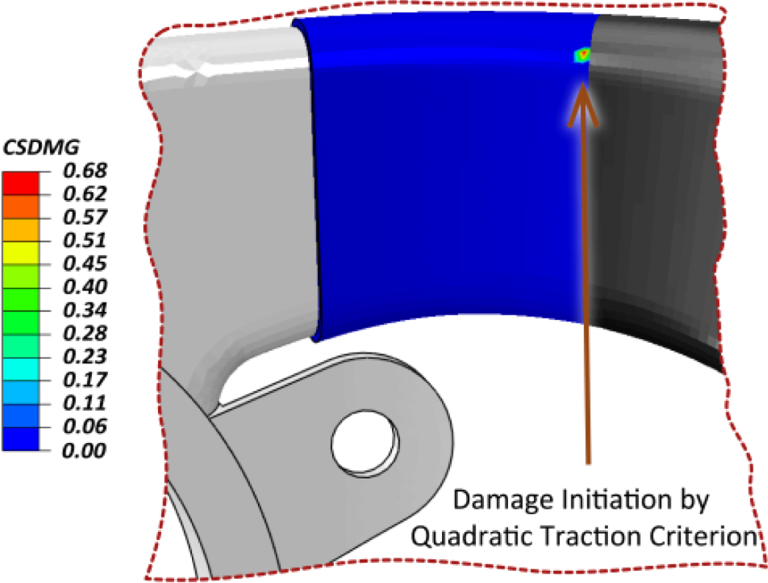
Figure 5. Iteration 2 with epoxy layer ∼0.4 mm: Damage localization based on a quadratic traction criterion.
The feasibility of the single step, co-curing concept (CFRP and adhesive epoxy layer) directly on the aluminum carrier has been attested in a prototype dummy-polymer motor-housing element created by additive manufacturing. The resulted prototype verified the feasibility of the process and a cross-section micrograph is shown in Figure 4 (Left), where it can be observed that the three domains are clearly distinct, with the adhesive epoxy layer to maintain its thickness that is critical for the relief of the local residual stresses.
5.1.3 3rd Iteration – design optimization for stress relief
Following the results of the previous iterations, further optimization is required to improve and assure the durability of the interface formed in the multi-material hip–pelvis component. Having identified that the main contributor in the interface stress state are the residual stresses after curing, which are intensified by the high local rigidity, the design was optimized by a compliant interphase layer during the 2nd iteration. In order to increase the compatibility of the main domains, aluminum and CFRP, the former one was revised to become more compliant in the region of bonding. To this end, the branches of the motor-housing aluminum carrier were extended and moreover they were redesigned to be hollow with ∼1.5 mm thick walls. Remarkably, this design revision provided a reduction of the anticipated normal surface tractions of ∼35% and on the shear stresses another 20%.
To further improve the stress state on the interface, the employed curing temperature was pushed to the lower required to cure both the epoxy layer and the prepreg CFRP, that is
![]() $80\,^{\circ }\text{C}$
. The solution of the FE models with redesigned geometry, and the modified temperature field at a
$80\,^{\circ }\text{C}$
. The solution of the FE models with redesigned geometry, and the modified temperature field at a
![]() $\unicode[STIX]{x0394}T=-60\,^{\circ }\text{C}$
, revealed a major reduction on the predicted stresses developed on the interface. In detail, the revised design plus the reduced temperature gradient provided a total reduction of ∼70% in normal surface tractions and ∼40% on the shear stresses. As a result, the reduction of the curing temperature by
$\unicode[STIX]{x0394}T=-60\,^{\circ }\text{C}$
, revealed a major reduction on the predicted stresses developed on the interface. In detail, the revised design plus the reduced temperature gradient provided a total reduction of ∼70% in normal surface tractions and ∼40% on the shear stresses. As a result, the reduction of the curing temperature by
![]() $20\,^{\circ }\text{C}$
, has an equivalent positive effect with the introduction of the hollow design as perceived by the aforementioned percentages of stress relief. The revised geometry and the corresponding results of the FE model are illustrated in Figure 6.
$20\,^{\circ }\text{C}$
, has an equivalent positive effect with the introduction of the hollow design as perceived by the aforementioned percentages of stress relief. The revised geometry and the corresponding results of the FE model are illustrated in Figure 6.
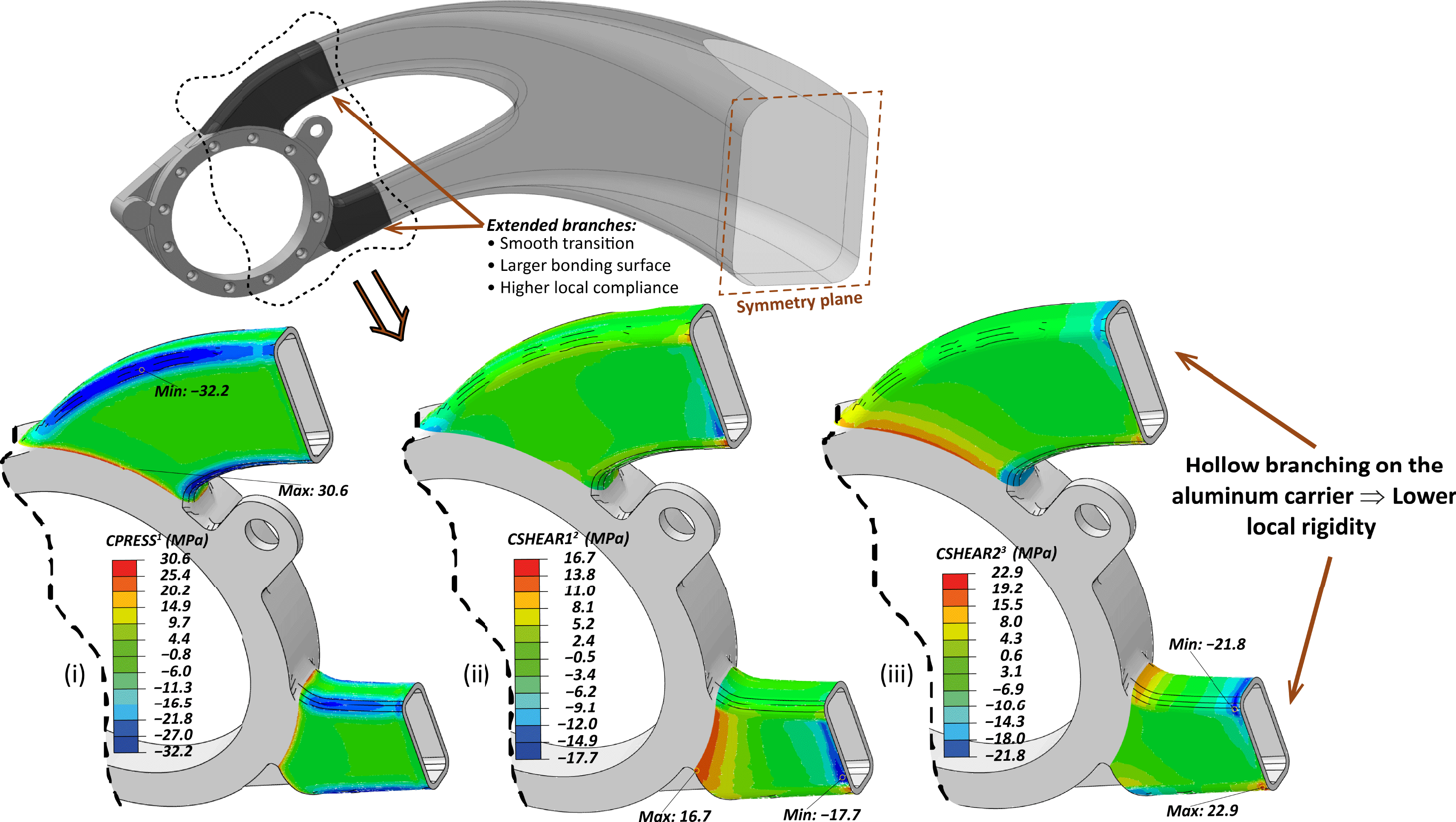
Figure 6. Iteration 3: (Top): Modified geometry. (Bottom): FE results of cohesive contact stress profile: (i) Normal; negative is in tension, (ii) Shear Vertical, (iii) Shear Horizontal.
5.1.4 Final iteration – optimum solution
The hollow sections tested with the FE scheme showed significant reduction of the developed surface tractions. However, some extended areas of high stresses, especially normal ones, are still present on the curved regions as seen in Figure 6. A better understanding of the process is provided by observing the deformed shape of the aluminum hollow branches in Figure 7 (Left). As depicted in this deformed state (scaled by
![]() $\times 100$
), after the thermal cool-down step, the aluminum part that has greater tendency for shrinkage, is blocked from the CFRP shell especially in the curved corners that its rigidity is higher, showing a tendency to a hourglass shape. As a result, the bonded interfaces of the planar subdomains suffer lower stresses than the curved ones.
$\times 100$
), after the thermal cool-down step, the aluminum part that has greater tendency for shrinkage, is blocked from the CFRP shell especially in the curved corners that its rigidity is higher, showing a tendency to a hourglass shape. As a result, the bonded interfaces of the planar subdomains suffer lower stresses than the curved ones.
Since the layered CFRP shell cannot become more flexible without sacrificing its durability, the focus is directed to the aluminum domain. To this end, slots were introduced in the geometry of the hollow sections and the solution of numerical model provided the stress state depicted in Figure 7 (Right). The existence of the slots gave rise to significant flexibility to the shape to adapt to the CFRP shell with some high stresses to persist on the curved areas, though.
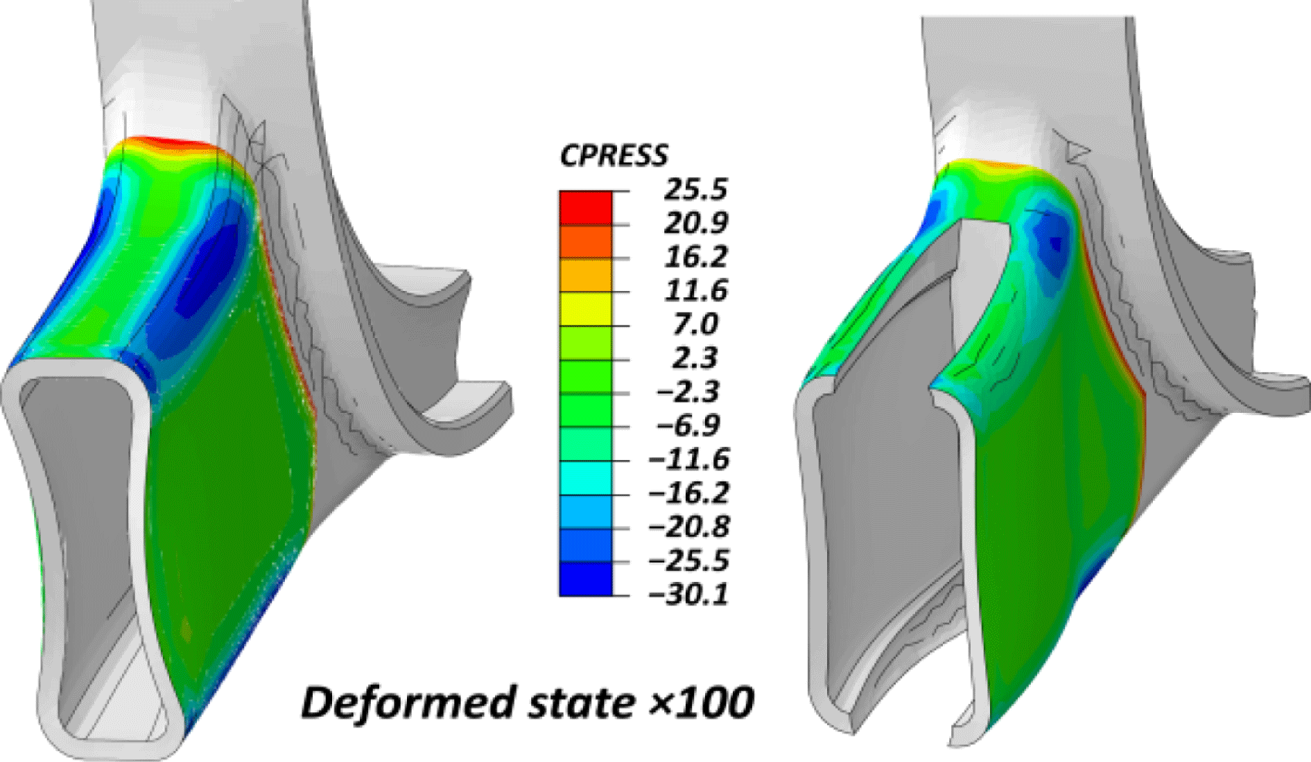
Figure 7. FE results of cohesive contact normal stress profile due to thermal shrinkage on the deformed state scaled by
![]() $\times$
100.
(Left): Continuous hollow section. (Right): Example with slots.
$\times$
100.
(Left): Continuous hollow section. (Right): Example with slots.
An optimal interface traction profile is obtained by the elimination of the curved regions that leads to relaxation of the local locking and the aluminum part can follow smoothly the shape imposed by the CFRP shell with the low or minimal shrinkage, as illustrated in Figure 8. Hence, the optimum slot placement was the one that eliminated the most stressed regions. Such slots can be machined during the fabrication of the aluminum part, with no trouble. Nevertheless, those regions have to be covered during the lamination and the curing process. 3D printed plastic inserts can be used to fill the created gap, as illustrated in Figure 9 (Left), and at the end of the process become integrated to the polymer shell. It is important to note that, the contours around the sharp edges of the slots have some limited stress concentrations (see Figure 8) that are diminished when the sharp edges are replaced by chamfers or radii of 1 mm. Corresponding edge smoothening should be adopted on the 3D printed plastic inserts to assure smooth transitions on the polymer counterpart.
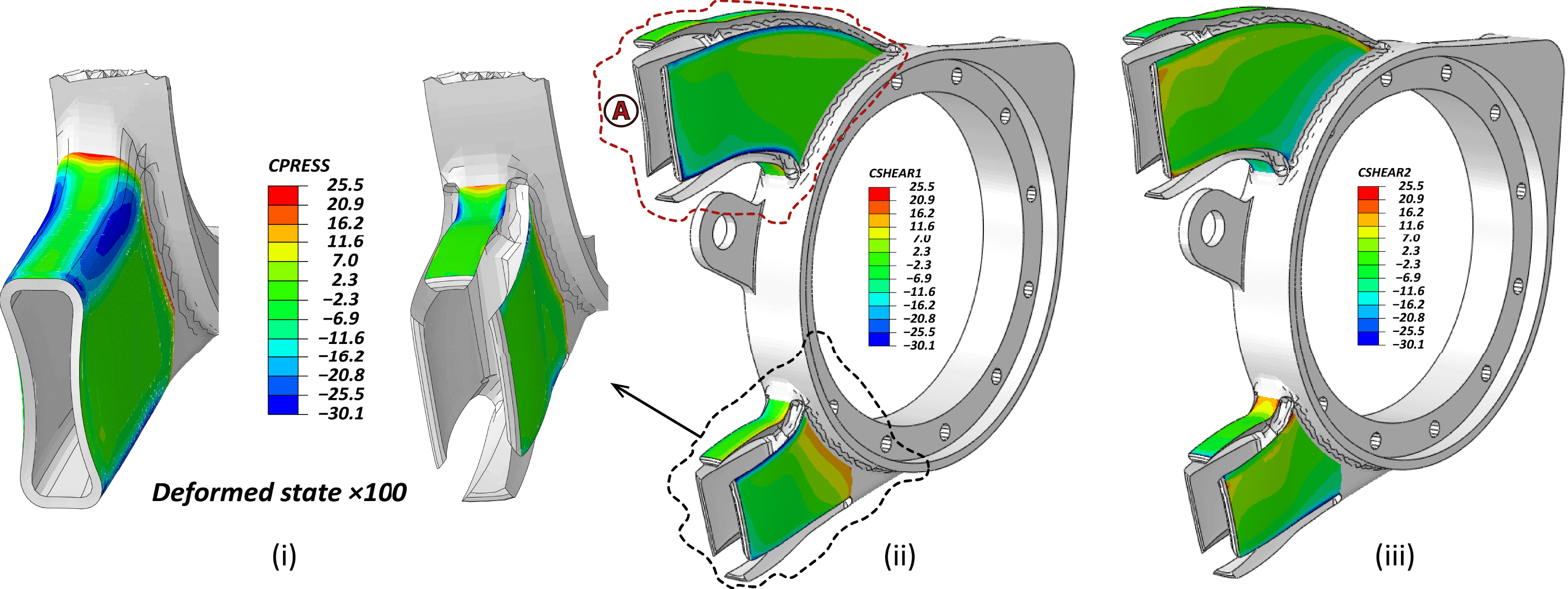
Figure 8. FE results of cohesive contact stress profile of the optimum geometry: (i) Normal; negative is in tension, (ii) Shear Vertical, (iii) Shear Horizontal.
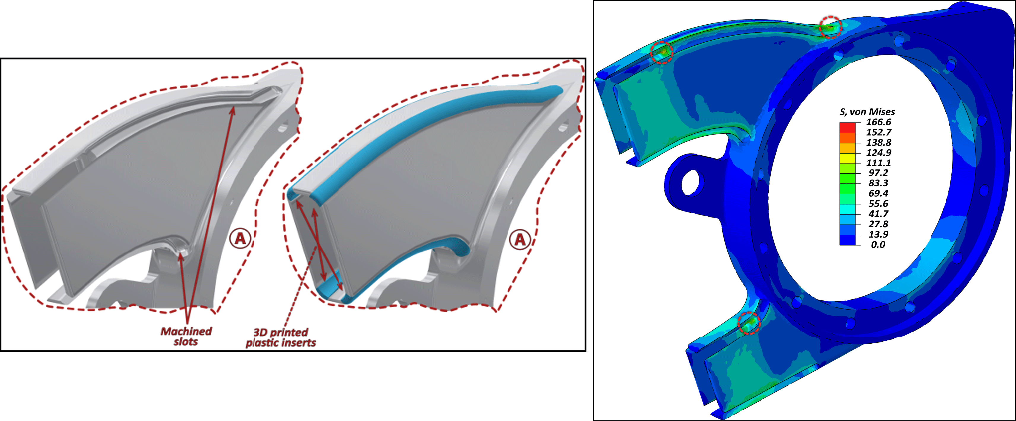
Figure 9. (Left): Detail on area Ⓐ of Figure 8: 3D representation of the machined slots and the 3D printed plastic inserts. (Right): Equivalent 3D von Mises stress state color plot on the aluminum domain, with slots induced.
Figure 9 (Right) shows the von Mises equivalent stress state of the loaded aluminum domain with designed slots. The maximum predicted stresses are below 170 MPa that are way below the yield limit of an aluminum material of EN AW 70XX family. Interestingly, no local weakening or stiffness reduction of overall branched geometry is observed, since the part is highly reinforced on the bonded regions that comprise hybrid aluminum and CFRP domains.
In summary, the proposed design is an optimum one, having modified at their most all parameters that can reduce the interface tractions due to residual stresses. Thus, curing temperature and local geometry design improvements, are proposed to achieve the compliance compatibility of the contributing multi-material domains, always respecting the given geometrical, functionality and single fabrication step conditions.
5.2 Experiments
The numerical optimization scheme showed that the optimum solution in terms of interface durability comprises tailored local geometry and a compliant interphase epoxy layer in between the aluminum and CFRP domains. Assuming that CFRP and epoxy have very good compatibility, since the two epoxy thermosets (matrix and adhesive) should blend and join during the curing, the critical interface to characterize is the one of aluminum epoxy. As a result the experimental campaign focused on acquiring representative values for strength and toughness of the aluminum–epoxy interface, considering typical plain and SB aluminum surface as discussed in Section 4.2.
A comparison between an SB and a ‘plain’ surface obtained by hot rolling (similar to a fine milling process, non-rectified) is illustrated in Figure 10. The micrographs obtained by a video microscope (Keyence VHX-5000) are illustrated on the left-hand side, with a color map to indicate the roughness measurements. Typical profile measurements are shown in the right-hand side for both plain and SB domain. For the plain surface the arithmetical mean height,
![]() $Ra$
, was ∼
$Ra$
, was ∼
![]() $0.7~\unicode[STIX]{x03BC}\text{m}$
and the root mean square deviation,
$0.7~\unicode[STIX]{x03BC}\text{m}$
and the root mean square deviation,
![]() $Rq$
, was
$Rq$
, was
![]() ${\sim}0.9~\unicode[STIX]{x03BC}\text{m}$
. The corresponding values for the SB were about three times higher with
${\sim}0.9~\unicode[STIX]{x03BC}\text{m}$
. The corresponding values for the SB were about three times higher with
![]() $Ra=2.1~\unicode[STIX]{x03BC}\text{m}$
and
$Ra=2.1~\unicode[STIX]{x03BC}\text{m}$
and
![]() $Rq=2.6~\unicode[STIX]{x03BC}\text{m}$
.
$Rq=2.6~\unicode[STIX]{x03BC}\text{m}$
.
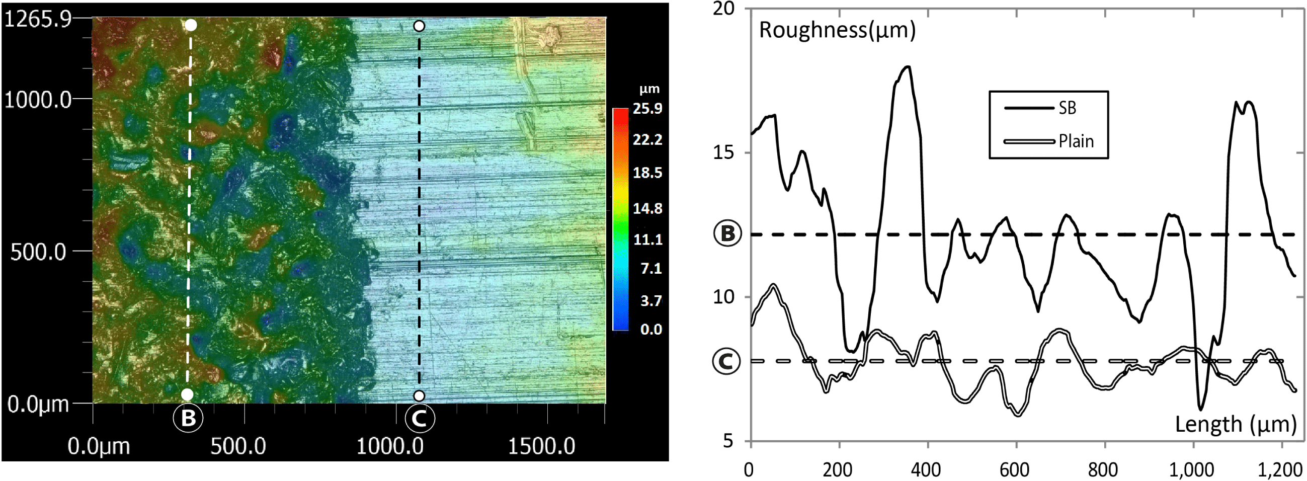
Figure 10. (Left): Microscopy and color map of the roughness obtained by the video microscope. (Right): Roughness profile measurements on two typical segments (SB and plain), with the mean lines indicated.
5.2.1 Fracture tests
To conduct the fracture experiments a sandwich plate (
![]() $400\times 280~\text{mm}^{2}$
) was fabricated comprising two 7022-T651 aluminum rolled panels of 8. 2 ± 0. 1 mm thickness and two plies of Gurit SA-80 prepreg adhesive with the anticipated ∼0.4 mm cured-ply thickness. Half of the available area on the aluminum plates was SB, while the rest was left intact. Surface purification was processed as described in Section 4.2. In the inner side of the plates, a
$400\times 280~\text{mm}^{2}$
) was fabricated comprising two 7022-T651 aluminum rolled panels of 8. 2 ± 0. 1 mm thickness and two plies of Gurit SA-80 prepreg adhesive with the anticipated ∼0.4 mm cured-ply thickness. Half of the available area on the aluminum plates was SB, while the rest was left intact. Surface purification was processed as described in Section 4.2. In the inner side of the plates, a
![]() $400\times 75~\text{mm}^{2}$
strip of ETFE 13 μm thick film was introduced during the fabrication procedure between the first aluminum panel and the prepreg plies to form the precrack on the aluminum–epoxy interface under investigation. This sandwich plate was cured at 80 °C for 12 h, under vacuum conditions and 3 bar pressure in an autoclave and used to cut specimens for both mode I and mode II fracture tests. All produced specimens had a total length of 280 mm. In order to optimize the use of material, the specimens for mode I, were cut in a width of 10 mm, expecting to follow a plane strain approximation according to Pappas and Botsis (Reference Pappas and Botsis2016), while the ones for mode II at 25 mm width, as in Mencattelli et al. (Reference Mencattelli, Borotto, Cugnoni, Lazzeri and Botsis2018). Specimen preparation and apparatus for the testing of the mode I experiments were the same with the ones reported in Pappas and Botsis (Reference Pappas and Botsis2016). The corresponding ones for mode II were the ones reported in Mencattelli et al. (Reference Mencattelli, Borotto, Cugnoni, Lazzeri and Botsis2018) using the 4ENF configuration with ball bearings, mounted though in an MTS® hydraulic testing machine equipped with a 100 kN load cell, since high loads were expected (loads up to 12 kN were finally measured). The choice of thickness of the aluminum panel was made to avoid any plastic deformation far from the crack front based on the range of anticipated toughness.
$400\times 75~\text{mm}^{2}$
strip of ETFE 13 μm thick film was introduced during the fabrication procedure between the first aluminum panel and the prepreg plies to form the precrack on the aluminum–epoxy interface under investigation. This sandwich plate was cured at 80 °C for 12 h, under vacuum conditions and 3 bar pressure in an autoclave and used to cut specimens for both mode I and mode II fracture tests. All produced specimens had a total length of 280 mm. In order to optimize the use of material, the specimens for mode I, were cut in a width of 10 mm, expecting to follow a plane strain approximation according to Pappas and Botsis (Reference Pappas and Botsis2016), while the ones for mode II at 25 mm width, as in Mencattelli et al. (Reference Mencattelli, Borotto, Cugnoni, Lazzeri and Botsis2018). Specimen preparation and apparatus for the testing of the mode I experiments were the same with the ones reported in Pappas and Botsis (Reference Pappas and Botsis2016). The corresponding ones for mode II were the ones reported in Mencattelli et al. (Reference Mencattelli, Borotto, Cugnoni, Lazzeri and Botsis2018) using the 4ENF configuration with ball bearings, mounted though in an MTS® hydraulic testing machine equipped with a 100 kN load cell, since high loads were expected (loads up to 12 kN were finally measured). The choice of thickness of the aluminum panel was made to avoid any plastic deformation far from the crack front based on the range of anticipated toughness.
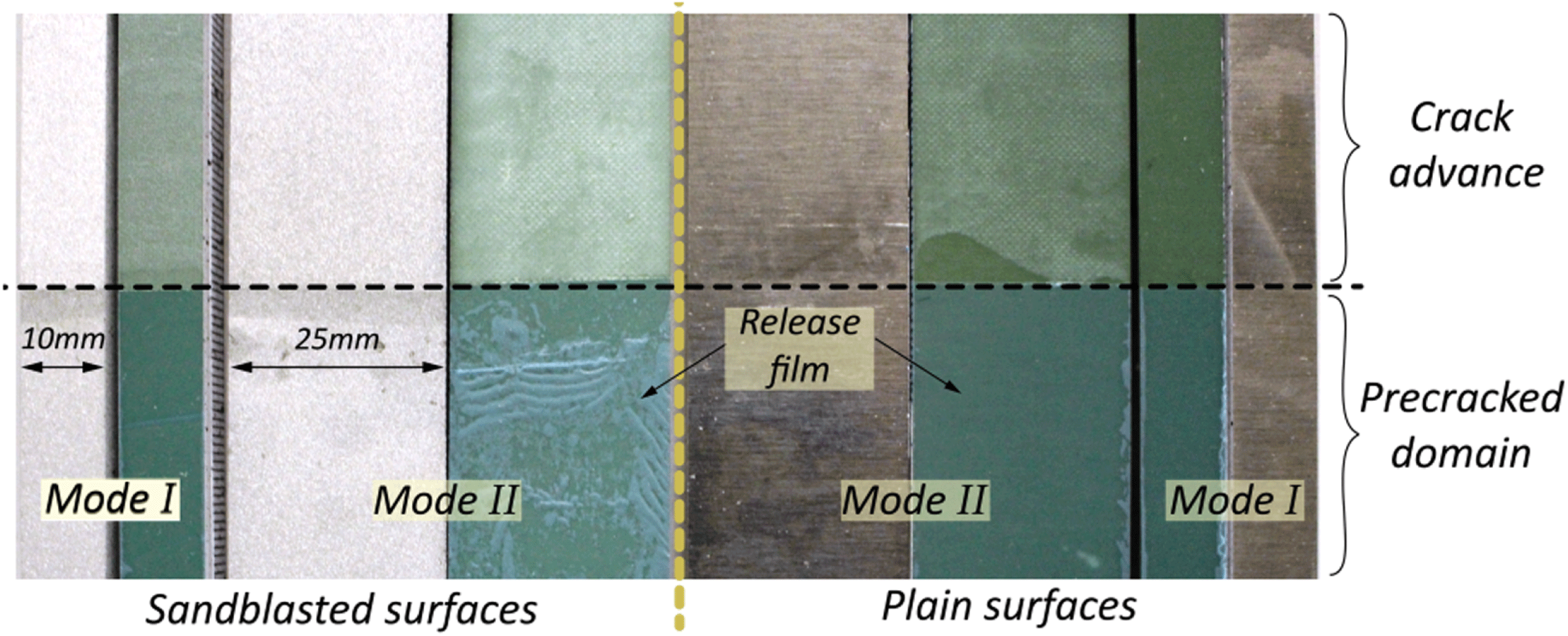
Figure 11. Typical conjugate fracture surfaces of mode I and II specimens: (Left): Sandblasted. (Right): Plain surfaces.
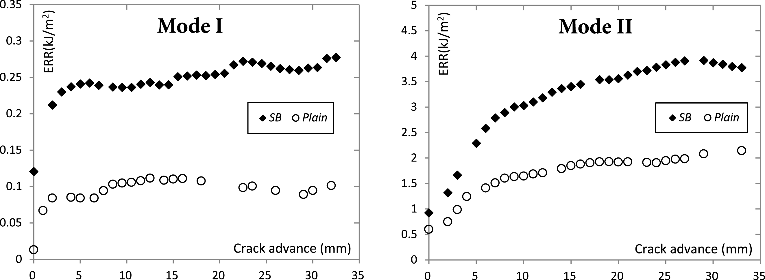
Figure 12. Mean experimental R-curves: (Left): Mode I. (Right): Mode II. A variation of up to 40% is observed for the plain-surface specimens, and 10% for the SB ones. These variations are not shown in the figure for better clarity.
Typical conjugate fracture surfaces of the experimental fracture testing series are illustrated in Figure 11. In all cases adhesive failure was observed, with some damage on the polymer to be noticed on the mode II series for both SB and plain surfaces by the whitish finish of the epoxy fracture faces. The calculated experimental R-curves of all series are depicted in Figure 12. For mode I, the compliance method was used (ISO 25217 2009), while for mode II the analytical expression included in Martin and Davidson (Reference Martin and Davidson1999). A significant positive effect of sandblasting was captured for the initial fracture toughness (by visual crack advance) in mode I with an increase of
![]() ${\sim}10\times$
, while the plateau values of both modes I and II and the initiation of the latter, are approximately double. The results reported in Figure 12, are averages of four specimens for mode I and three for mode II. A large scatter was observed for the plain-surface specimens due to stick–slip behavior leading to an approximate standard deviation as high as 40% for ERR and crack advance. Regarding the SB series, only a 10% of corresponding deviations were observed. As a result, the sandblasting has a positive effect in the toughness and damage tolerance of the interface and this is attributed to the increased roughness (Figure 10 (Right)) that increases the effective area (in mode I) and promotes locking (in mode II) in the microscale, despite the fact that interfacial failure occurs in both cases (Figure 11). Moreover, the epoxy has completely wetted the rough surface, as shown in Figure 11 and this allowed the positive effect to be revealed. Additionally, it is worth mentioning that sandblasting has the advantage of high reproducibility in comparison with manual abrasion process that is proposed in ISO 17212 (2004).
${\sim}10\times$
, while the plateau values of both modes I and II and the initiation of the latter, are approximately double. The results reported in Figure 12, are averages of four specimens for mode I and three for mode II. A large scatter was observed for the plain-surface specimens due to stick–slip behavior leading to an approximate standard deviation as high as 40% for ERR and crack advance. Regarding the SB series, only a 10% of corresponding deviations were observed. As a result, the sandblasting has a positive effect in the toughness and damage tolerance of the interface and this is attributed to the increased roughness (Figure 10 (Right)) that increases the effective area (in mode I) and promotes locking (in mode II) in the microscale, despite the fact that interfacial failure occurs in both cases (Figure 11). Moreover, the epoxy has completely wetted the rough surface, as shown in Figure 11 and this allowed the positive effect to be revealed. Additionally, it is worth mentioning that sandblasting has the advantage of high reproducibility in comparison with manual abrasion process that is proposed in ISO 17212 (2004).
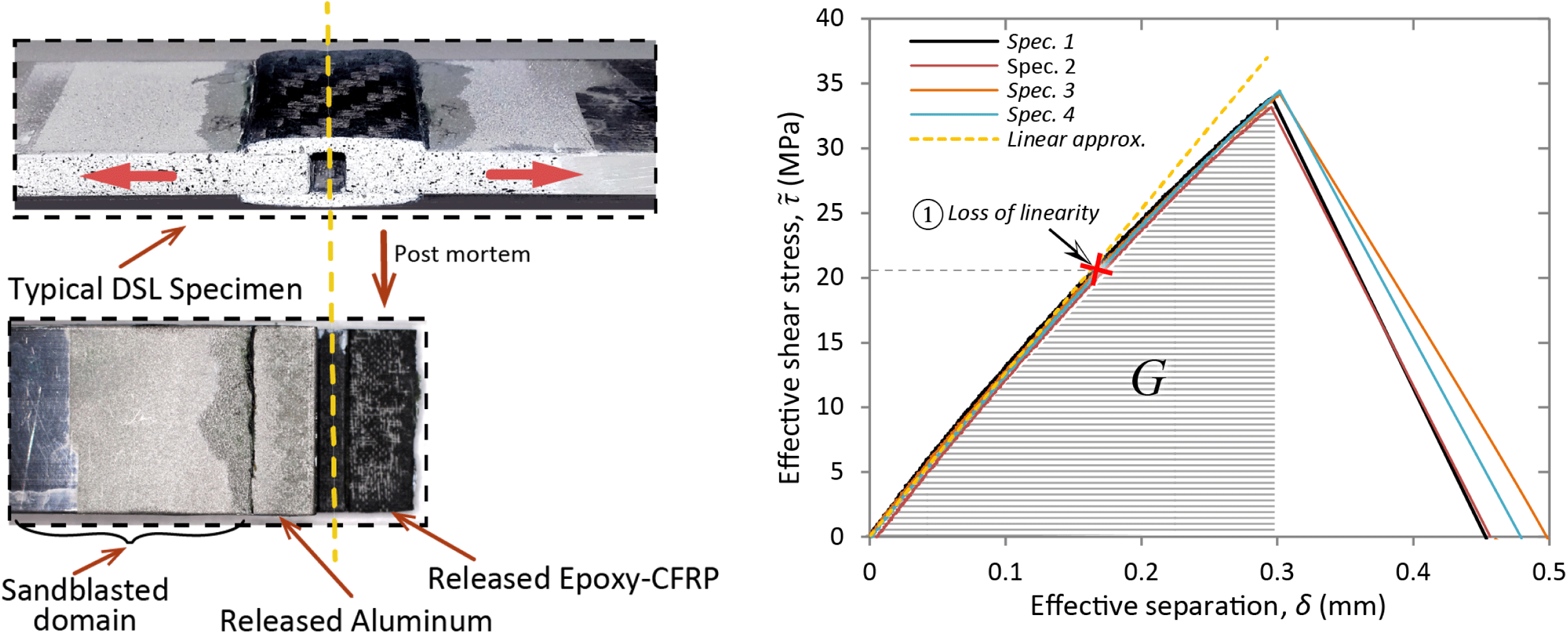
Figure 13. DSL experiments: (Left): Photograph of a typical specimen and the released surfaces post failure. (Right): Stress separation; see text for details.
5.2.2 DSL tests
Having identified that sandblasting has a significantly positive effect on the toughness of the interface, DSL experiments on solely SB surfaces were conducted to estimate the durability safety factor of the designed interface. DSL symmetric specimens of type B according to ASTM Standard D3528 – 96 (2016) were fabricated and tested. The middle adherend was aluminum (EN AW 6060-T6) bars of a
![]() $6\times 25~\text{mm}^{2}$
section, chosen to withstand the anticipated stresses without plasticity. The lower and upper adherends were patches of 2 mm thick quasi-iso layered CFRP, as in the final hip–pelvis component, adhered on the aluminum bars by two layers of Gurit SA-80 prepreg adhesive (Figure 13 (Left)). These specimens were cured using the aforementioned autoclave process, by means of a special mold. Therefore, the tested interface is equivalent to the one in the prototype structure. The overlap length, at the end of the curing, was
$6\times 25~\text{mm}^{2}$
section, chosen to withstand the anticipated stresses without plasticity. The lower and upper adherends were patches of 2 mm thick quasi-iso layered CFRP, as in the final hip–pelvis component, adhered on the aluminum bars by two layers of Gurit SA-80 prepreg adhesive (Figure 13 (Left)). These specimens were cured using the aforementioned autoclave process, by means of a special mold. Therefore, the tested interface is equivalent to the one in the prototype structure. The overlap length, at the end of the curing, was
![]() $\ell =8.75~\text{mm}$
.
$\ell =8.75~\text{mm}$
.
The DSL specimens were tested in the aforementioned MTS® hydraulic machine, measuring load and applied displacement (0.2 mm/min), while in a few specimens the local separation was acquired by means of digital image correlation (DIC). The DIC measurements showed that the local separation can be accurately deducted by subtracting the elongation of the non-adhered aluminum domain from the applied displacement. The experimental shear stress vs. the local separation data of the DSL tests are shown in Figure 13 (Right). Loss of linearity is identified at ∼21 MPa while the ultimate measured shear strength is ∼33.5 MPa.
The post-failure released surfaces depicted in Figure 13 (Left) show a mixed cohesive–adhesive failure with the cohesive regions to be close to the mid-plane of the DSL lap. This behavior can be explained by the stress state obtained by an FE model equivalent of the DSL specimen. The resolved model for an applied load of 9 kN (load at non-linearity point) showed that even though globally pure shear conditions are applied, locally some important normal stresses are developed, as depicted in Figure 14. The opening normal stresses appear on the domain where adhesive failure was observed, while compressive ones are developed toward the center of the specimen. Moreover, the effective shear stress, calculated by the applied load and the adhered area, is practically the mean value of the shear stresses developed on the interface. As a result the ultimate measured shear strength seen in Figure 13 (Right) represents a lower bound.
Interestingly, the area under the stress-separation curves (
![]() $G$
in Figure 13 (Right)) is ∼ 3. 5 kJ/m2, which corresponds to the measured mode II fracture toughness. The separation after the pick load is not considered in this measurement since it is mainly dominated by friction.
$G$
in Figure 13 (Right)) is ∼ 3. 5 kJ/m2, which corresponds to the measured mode II fracture toughness. The separation after the pick load is not considered in this measurement since it is mainly dominated by friction.
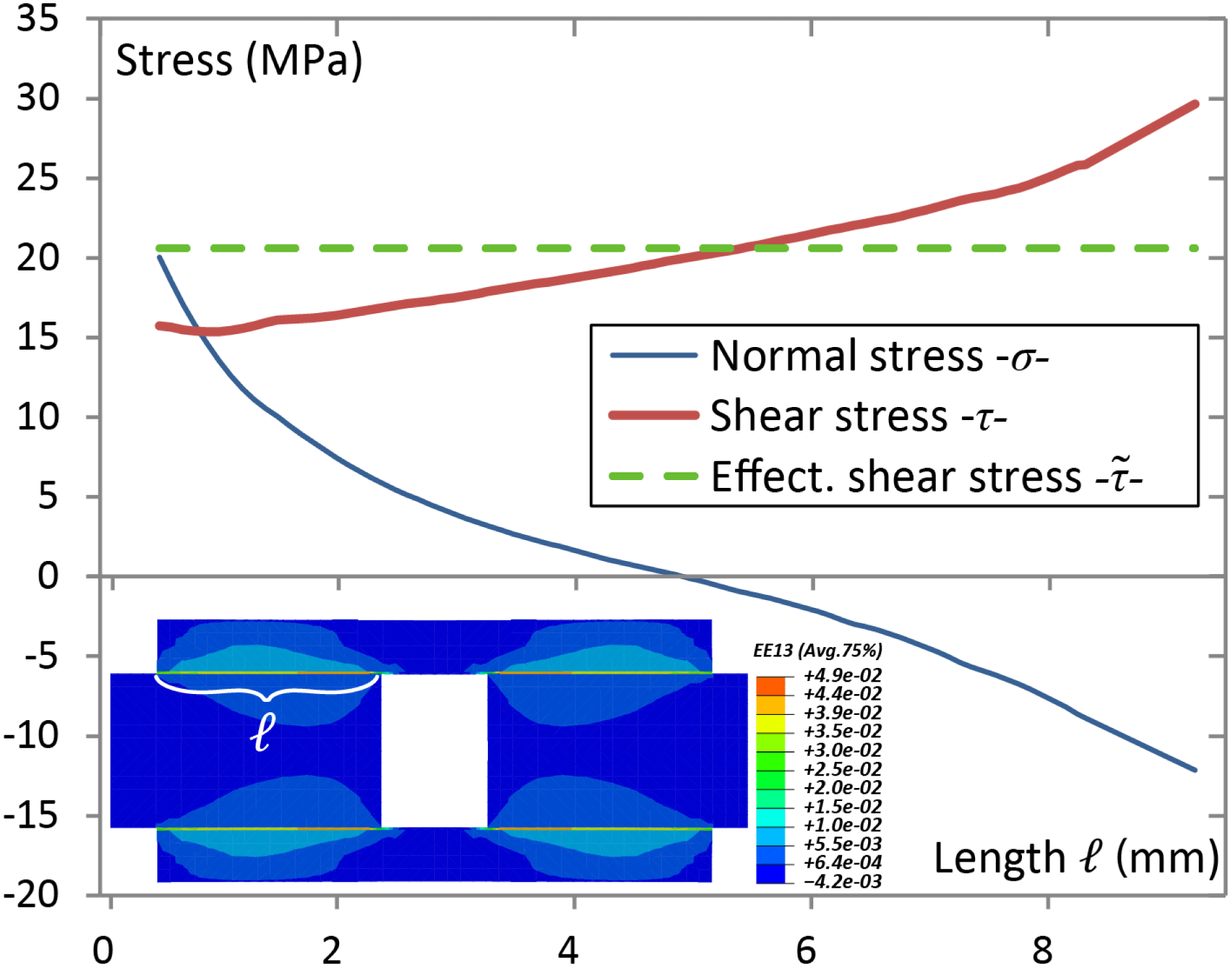
Figure 14. Stress state at the interface of the DSL specimen from FE model resolved for the state
![]() $\unicode[STIX]{x2460}$
indicated in Figure 13 (Right); see text for details.
$\unicode[STIX]{x2460}$
indicated in Figure 13 (Right); see text for details.
5.2.3 Identification of safety factor
The maximum expected stresses in the aluminum–epoxy interface of the designed hip–pelvis multi-material component should not exceed 16 MPa (shear) and 10 MPa (normal), according to the optimum joint geometry design (Figure 8, excluding the sharp edge effect, see Section 5.4). A
![]() $\frac{2}{1}$
ratio between the ultimate normal and shear strength for similar interfaces is reported in Ikegami et al. (Reference Ikegami, Fujii, Kawagoe, Kyogoku, Motoie, Nohno, Sugibayashi and Yoshida1996), Sarrado et al. (Reference Sarrado, Turon, Costa and Renart2016), which leads to a normal strength of ∼67 MPa. Referring to this value, an important safety factor, higher than 6 is formed with respect to the normal interface stresses that is considered a reasonable value, taking into account the very low mode I initial toughness and damage tolerance of the interface.
$\frac{2}{1}$
ratio between the ultimate normal and shear strength for similar interfaces is reported in Ikegami et al. (Reference Ikegami, Fujii, Kawagoe, Kyogoku, Motoie, Nohno, Sugibayashi and Yoshida1996), Sarrado et al. (Reference Sarrado, Turon, Costa and Renart2016), which leads to a normal strength of ∼67 MPa. Referring to this value, an important safety factor, higher than 6 is formed with respect to the normal interface stresses that is considered a reasonable value, taking into account the very low mode I initial toughness and damage tolerance of the interface.
Regarding the shear stresses’ safety factor, a value around 2.1 is approximated, which according to literature should be sufficient to satisfy the fatigue limit estimated approximately as 45% of the strength measured in quasi-static, monotonic conditions of such interfaces (Curley et al. Reference Curley, Jethwa, Kinloch and Taylor1998).
It is worth mentioning that the fabricated component following the optimum joint design presented herein, showed no damage on the interfaces when imposed to moments and forces three times higher than the service loads, under monotonic conditions (Kussmaul et al. Reference Kussmaul, Biedermann, Pappas, Jónasson, Winiger, Zogg, Türk, Meboldt and Ermanni2019).
6 Concluding remarks
The results of the current study show that a thorough optimization of the interfaces involved in a multi-material structural component enables the conception of a lightweight, highly durable FRP–aluminum part. A single fabrication step has plenty of advantages. Nevertheless, the residual stresses after curing play a critical role since it was demonstrated that stresses high enough to damage the interface may develop during the cool-down process. The origin of such stress state is the high thermal expansion coefficient mismatch originating from the very low coefficient of carbon fibers and the high one of light metals such as aluminum or titanium. A fundamental role in stress relaxation plays the modification of the local rigidity of the domains involved in the bonded region. The introduction of a compliant resin layer in combination with optimization of the metallic domain gave rise to a moderately stressed interface, allowing high durability. The proposed solution demonstrates that such interfaces can exist in multi-material structural components avoiding risk of damage, optimizing the lightweight nature of the part and allowing tailored geometry, as compared to the conventional bolting or riveting techniques that usually compromise the integrity of the CFRP domain.
The implemented design optimization approach to reduce the local rigidity of the metallic counterpart can be further generalized. The slotted rectangular transition domains were shown to be the optimum geometry since the multiple flat, thin-walled sections were capable of efficiently transferring the service loads allowing at the same time the residual thermal stresses to be relaxed. A general proposition that can serve as a guideline, when dealing with thin-walled structures on the interface, can be formed as: elimination of the regions where the interface is highly stressed, simply relaxes the overall stress level, such as the one conducted by elimination of the curved regions. This guideline is exactly the opposite of the one implemented in optimizing the stress state of a continuous component where extra material is introduced in the highly stressed domains.
This example can be projected to tubular/cylindrical sections commonly found in mass production. A cylindrical section has high and homogeneous rigidity that is expected to be troublesome in terms of residual interface stresses when used in an aluminum–CFRP structure. However, similar optimization approach to the one adopted in the current study, implemented on the example of the bioengineering application, can be applied. The proof of concept is illustrated in Figure 15 over the results of a numerical model–case study. Here a typical CFRP quasi-iso domain is coupled with a cylindrical aluminum one and the equivalent of the cool-down step after curing is modeled. The results for the normal interface stresses show that the cylindrical domain suffers high uniform stresses that can be significantly relaxed by implementing slots similar to the ones seen in Figures 8 and 9.

Figure 15. (Left): Concept and boundary condition of the numerical model with a cylindrical multi-material domain case study. (Right): FE results of cohesive contact normal stress profile on a hypothetical cylindrical connection. Negative is in tension. The color spectrum is reversed for better clarity.
The residual stresses problem analyzed herein resembles the one of the thermal stresses in service, such as the one described in the introduction for the gearbox casing. The approach described herein is expected to have equally positive effect in relieving thermal service stresses.
In this study it was demonstrated that the durability, of interfaces created in FRP–metallic hybrid components, can be optimized by both targeted design adjustment and enhancement of the strength and toughness of the interface with procedures such as sandblasting that is characterized by simple implementation and high repeatability.
Acknowledgments
Funding for this study has been provided by SFA-Advanced Manufacturing initiative of the ETH Board, under the ‘CFRP-AM, Individualized cost-efficient and sustainable ultra-lightweight structural components’ project and the work was carried out in collaboration with pd|z and CMASLab, ETHZ. The authors acknowledge the close cooperation with Mr. R. Kussmaul and Mr. M. Biedermann.


