Introduction
The WISSARD (Whillans Ice Stream Subglacial Access Research Drilling) traversable hot-water drill system (HWDS) was designed to create ice boreholes up to >1m in diameter, to a depth of >800 m. The system is considered a medium- to large-size drill and was designed to be modular and scalable (larger or smaller). Upon the University of Nebraska–Lincoln’s (UNL) receipt of the build contract, there was an 18 month window to complete the design, fabrication and delivery of the system. The project requirements dictated that the system be containerized for integration with the US Antarctic Program’s (USAP) South Pole traverse infrastructure and available ski kits provided by the Antarctic Support Contractor. While a preliminary concept of the WISSARD HWDS’s instrumentation had been sketched out prior to the build, the final architecture, instrument specifications and data management systems were all conceived and implemented in <6 months. The resulting control system, and associated instrumentation, performed well in the field without insurmountable problems and the project was considered a success.
Drill System Description
A description of the design and basic components of the WISSARD HWDS is provided in Reference RackRack and others (2014). The primary modules include: (1) a melt tank (MT), (2) a 14 000 L capacity water supply tank (WST), (3) a water filtration and decontamination unit (WFU) as a standard 12.2 m long ISO container, (4) two heater-pump units (HPU-1, HPU-2) as standard 12.2 m long ISO containers, (5) a hose reel unit (HRU) as a 12.2 m long hi-cube ISO container and (6) a command-and-control module (C&C) as a 6.1 m long ISO container. There are also several auxiliary modules transferred from the IceCube Enhanced HWDS (Reference BensonBenson and others, 2014) that were integrated into the final WISSARD HWDS design, such as: (1) two containerized 225 kW generators, (2) a power distribution module (PDM) and (3) a day fuel tank (DFT) (Fig. 1).
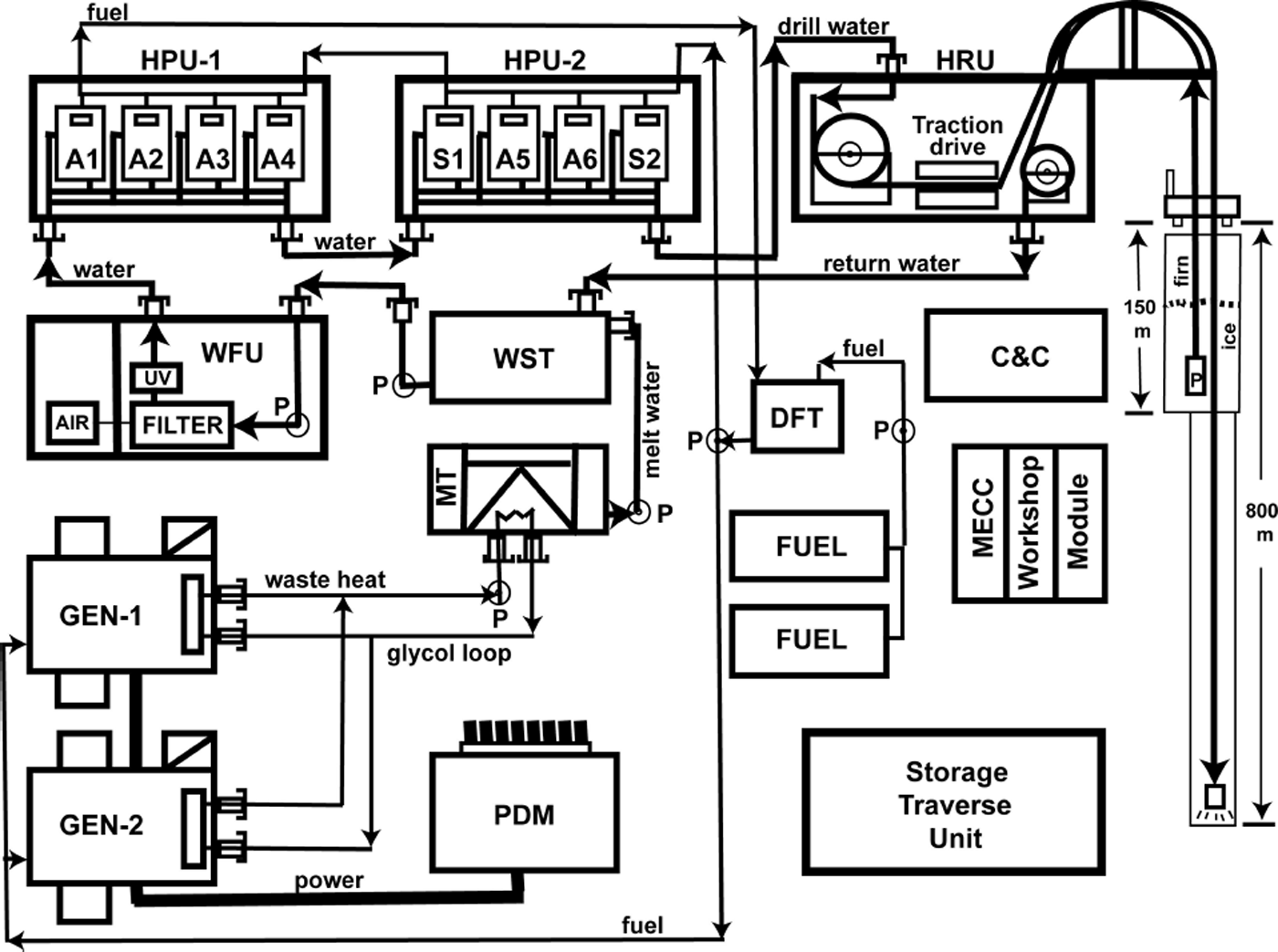
Fig. 1. Schematic diagram of the WISSARD hot-water drill system showing major modules described in the text, as well as circulation paths for power, fuel and water to the various modules.
Control System Overview
The control system was designed around a number of basic principles. First and foremost was the personal safety of the operators, followed by system reliability, modularity/flexibility and rapid deployability.
An off-the-shelf Allen-Bradley Compact Guardlogix® industrial Programmable Automation Controller (PAC) was chosen as the system controller, as this platform provided for easy future expansion. It was temperature-rated to –40°C, and possessed the ability to manage integrated multi-redundant safety systems with relative ease.
Safety-rated features of this system include redundant sets of electrical contacts on signal lines. Emergency process stops also included fully redundant signal lines to each device. Any safety-critical components were polled more frequently by the PAC at 20 ms (maximum) intervals compared to the standard 500 ms. Safety-critical packets also receive priority processing and transmission. Each hose or cable reel used a motor brake system for primary stopping power and a redundant hydraulic brake system attached directly to the drum shaft so that it could be stopped even in the event of a drive-chain, motor or gearbox failure.
The system-wide emergency stop system was implemented, such that any person could press an e-stop button and interrupt all processes that could potentially cause personal injury. This included stopping all high-pressure pumps, water heat generation, burner fuel flow, all heavy moving equipment (reels, level winds, traction device) and the power supply for the deck-mounted germicidal ultraviolet decontamination system. All containers had e-stops placed at building entrances, with additional camp-wide placements including the operations deck, and on all winch controls. The safety stop, designed per IEC standard 61508 (Edition 2.0 2010-04) and ISO 13849 (2006), is rated for a safety integrity level (SIL) of 3 in safety performance, which corresponds to a probability of dangerous failure between 10−8 and 10−7 h−1.
The control system was designed to allow the majority of drilling operations to be monitored and controlled by a single user. Despite this design intent, all measurement devices were also equipped with local readouts at the measurement point, and controls with local manual backups to ensure system usability and reliability. Analog measurements are made using analog-to-digital converters of 12-bit resolution. The operator is able to control motor speeds up to 0.1 Hz resolution.
EAD Control Systems, LLC, of Omaha, Nebraska, USA, was contracted to manage the control system development, as well as the fabrication and wiring of the electrical enclosures needed. During this process, two UNL drill operators integrated with EAD to become cross-trained as automation technicians and ensure that the infrastructure could be supported in the field.
Specific Instrumentation and Controls by Containerized System
Command-and-control module (C&C)
The command-and-control module housed the PAC along with two (redundant) laptop computers used for primary drill operation. All polled system values could be monitored from a total of three HMI (human–machine interface) screens, and all values were recorded to the local hard drive of both computers at 1 min intervals. The HMI screens updated and polled operator input at 4Hz. A local hardware e-stop trigger was also installed next to the drill operators in case of total computer failure.
Melt tank (MT)
The melt tank (see Reference Blythe, Duling and GibsonBlythe and others, 2014) was equipped with various gauges (local readout) and sensors (input to overall drill system data stream). Each manifold had a pressure and temperature gauge; the low-pressure submanifold had a temperature sensor tied into the main drill control system for remote monitoring of tank water temperature. A drop-in temperature probe was used for local monitoring of tank water temperature.
The glycol heating subsystem also had temperature and pressure sensors connected to the main control system. The water and glycol pumps were controlled using a local switch on a power distribution station near the melt tank. The main drill operator was able to monitor the status of these switches but was not permitted remote control over them. The MT operator interface can be seen in the upper left of Figure 2.
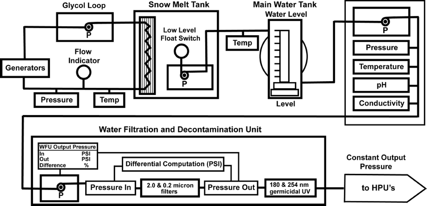
Fig. 2. HWDS user interface for monitoring and controlling the MT, WST and WFU.
Water storage tank (WST)
The water storage tank contained a submersible temperature sensor and pressure sensor for monitoring tank level. PH and conductivity sensors were placed on the output manifold as a means to measure drill water quality, and to help ensure brackish water is kept to a minimum in the system plumbing when operating the drill in sea-water access applications. Water is transferred from the tank via a pump with a motor contactor that can be controlled and monitored remotely. The WST operator interface can be seen in the upper right of Figure 2.
Water filtration and decontamination unit (WFU)
The water filtration and decontamination unit used two pressure sensors to measure differential pressure across the filters, and a system alarm was set in the event they become clogged. The container manifold has a local pump and motor, which are speed-controlled via closed loop PID (proportional-integral-derivative) control, to ensure a constant operator-defined output pressure from the filtration stages. This helps to consistently feed the heat generation stages even during system changes in tank pressure, heater activation or other system disturbances. Closed-loop PID gain tuning is handled programmatically through a series of set-up screens to define the process type, motor size, inertial load (provided automatically through motor controller setup) and user-desired response speed (fast, medium or slow). Gains can be further adjusted individually by the operator; however, no modification was needed past initial set-up at the ‘fast’ response speed. The WFU operator interface can be seen in the lower portion of Figure 2.
Heater pump unit(s) (HPU-1 and HPU-2)
The heater pump units contain up to four Alkota Cleaning Systems Inc. model 12257K pressure washers (i.e. high-pressure pump and diesel burner modules) inside each container. The flow rate and temperature (and hence energy production) for each module is monitored to determine individual system performance. These modules feed a common high-pressure manifold where pressure is monitored. The HPU container’s ambient temperature is monitored both for safety (to watch for signs of fire) and also for system performance as this room temperature slightly preheats both the incoming fuel and air intake to each unit. The remote operator can enable/disable fuel flow to each HPU container via a solenoid, and can also enable/disable pump motors. Remote starting of the diesel pump motors is not given, to ensure crew safety. The HMI screen for HPU-1 and HPU-2 can been in Figure 3.
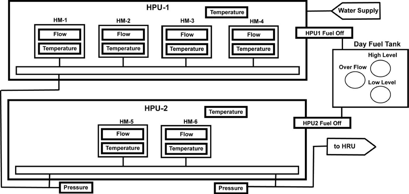
Fig. 3. HWDS user interface for monitoring and controlling HPU-1, HPU-2 and monitoring DFT.
Hose reel unit (HRU)
The hose reel unit’s main plumbing manifold monitors flow rate, pressure and temperature incoming from both HPU-1 and HPU-2. This manifold can supply hot water to a number of areas in the system, so a second flow measurement is taken at the hose reel input, to ensure accurate logging of energy added downhole.
The main drilling hose is paid out via a four-motor linear traction drive. Each motor has a shaft encoder, which is fed back to the motor controller. The operator inputs a desired payout speed and each motor operates at the same rate based on encoder feedback. The main hose reel is slave to the payout speed of the traction drive, and pays out hose to maintain a constant user-defined tension at the input of the traction drive. The amount of hose paid out is monitored with a separate encoder wheel to ensure accurate measurement even in the event of traction drive slippage. The hanging weight of the drill stem and hose is measured with a load cell, and monitored versus time on a scalable plot on the HMI in order to aid detection of unloading events indicative of excessive payout speed.
A separate manifold measures flow and temperature of the borehole water being returned by the downhole submersible pump, which is speed-controlled by the operator. Conductivity and PH are also monitored at this manifold to detect introduction of excessive amounts of sea water. The return water pump is raised and lowered with open-loop local manual controls. The level of water above the return pump is monitored with a submersible pressure sensor and is also displayed on a trend line similar to that of the load cell. The HMI screen for the HRU system can be seen in Figure 4.
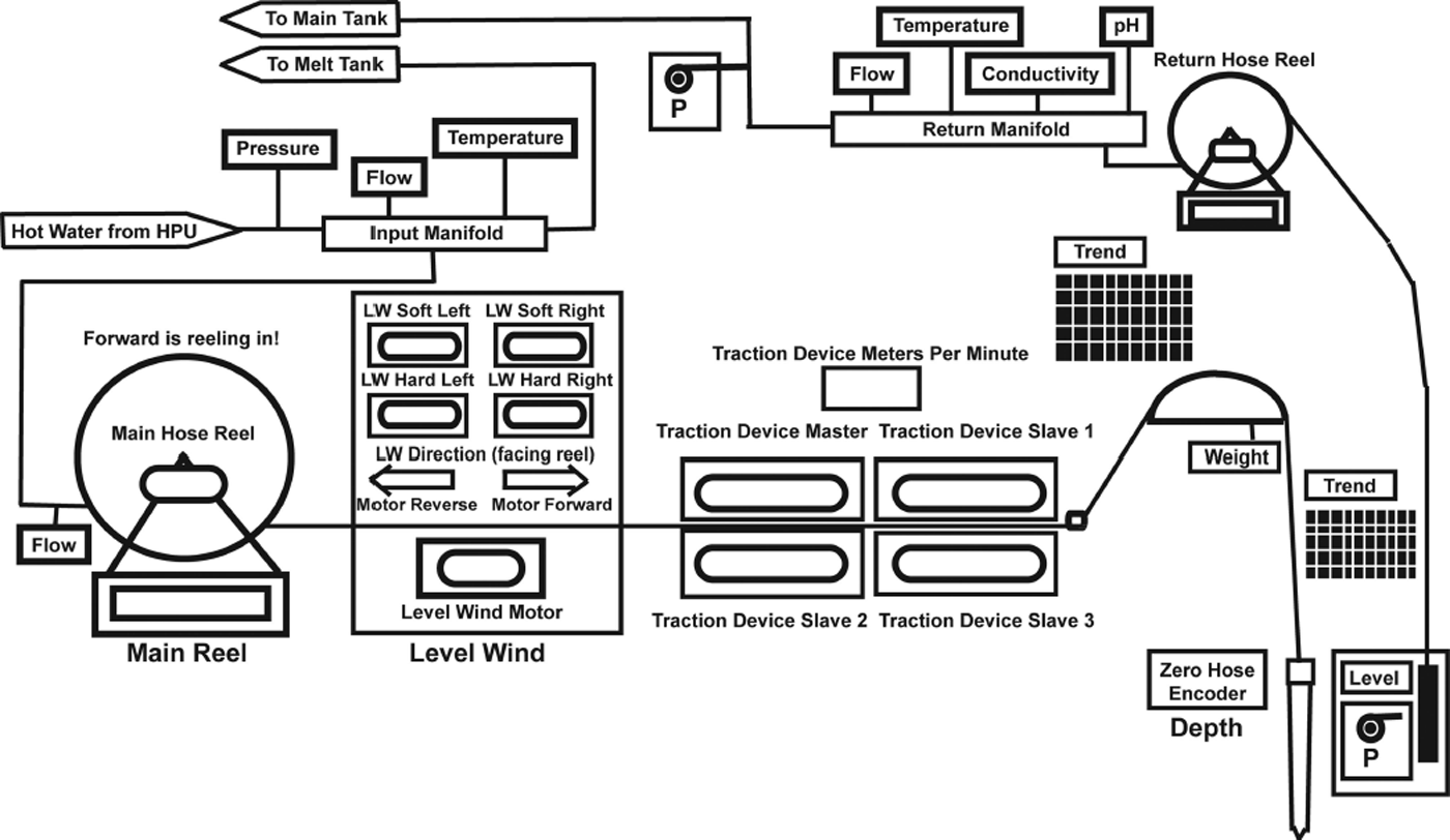
Fig. 4. HWDS user interface for monitoring and controlling the HRU.
Modular Input/Output Panel Description
Each of the seven main drill modules (C&C, HRU, HPU1&2, WFU, WST and MT) received its own input/output (I/O) panel, which aggregated their respective analog and digital sensor values, and sent control commands for local motors and relays. The panel itself was contained in a NEMA 4 (per NEMA 250-2003) rated enclosure, rated to withstand high-pressure and high-volume water directly to seals without allowing liquid penetration. Each enclosure contained a 20 W h battery backup in the form of a UPS (uninterruptible power supply) on the 120 V a.c. bus to maintain operations in case of power loss and to regulate potentially erratic a.c. waveforms created by the diesel generators. Each panel rectified incoming a.c. to a local 24 V d.c. bus for powering sensors and safety systems. An 800 W heater was installed for outdoor operation in extreme temperatures. Each I/O enclosure was powered through a single 30 A rated 120 V a.c. power line with watertight twist–lock connectors and watertight bulkheads. Each piece of instrumentation, as well as the Ethernet network connection, was also connected through NEMA 4 watertight bulkheads. This ensured minimal water intrusion and greatly simplified the system deployment and tear-down for deep-freeze winter storage (Figs 5 and 6).
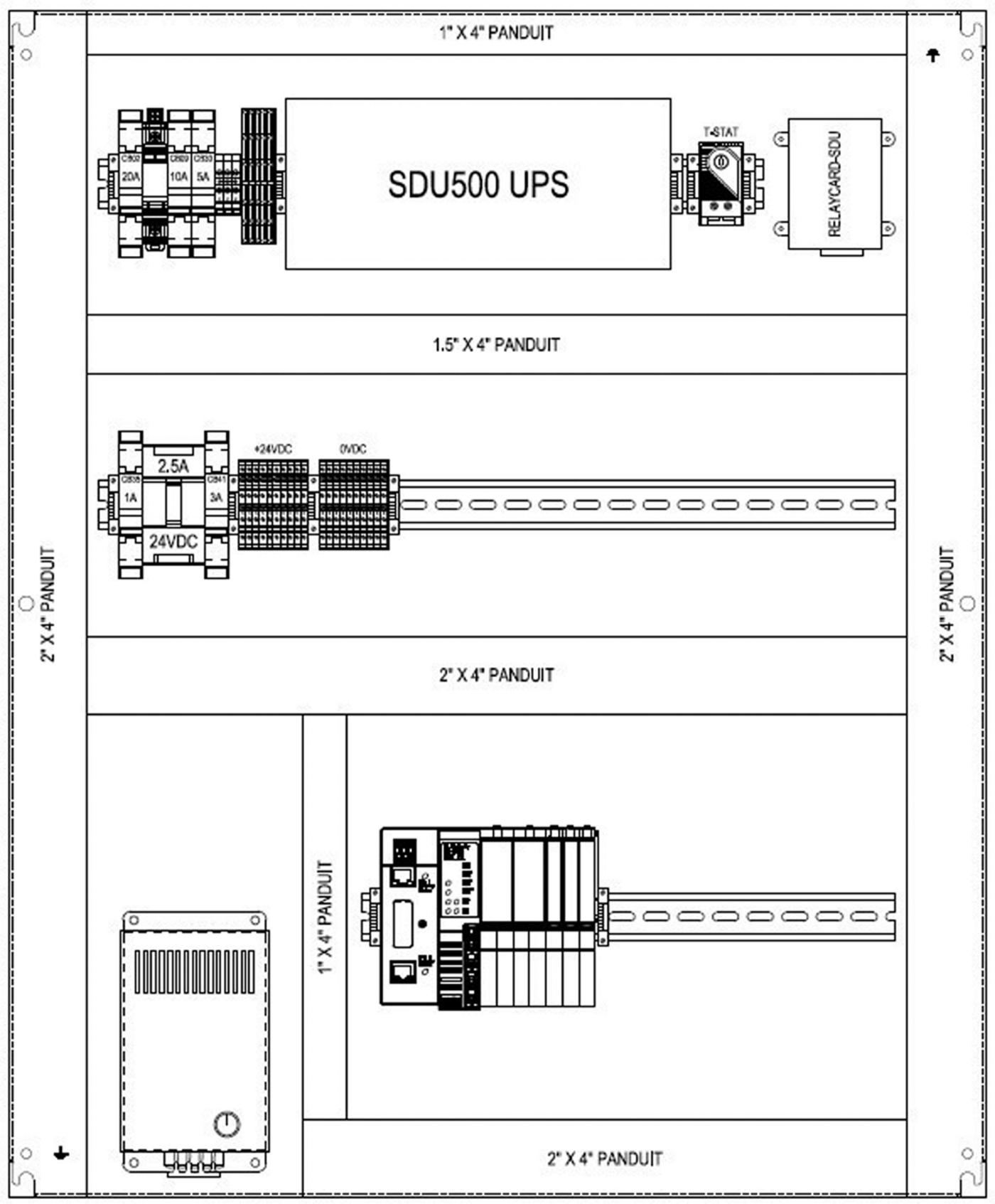
Fig. 5. Design drawing of a typical I/O panel.

Fig. 6. IO panel partially constructed (UPS has yet to be installed at top).
Component and Instrumentation Selection
The Allen-Bradley Compact Guardlogix® PAC accommodates standard as well as safety-rated components in the same system. The safety-rated line of industrial control components undergoes increased inspection and testing including shock, immersion, temperature, and full verification testing at the factory. Local sensors were aggregated into racks with easily expandable and replaceable I/O modules. Each of these racks communicates to the PAC via Ethernet in a ring network configuration.
All controllable safety features on the network were enabled or disabled using safe-off-style relays. The relay circuit is implemented such that the default (power off) position represents the shut-off or ‘safe’ state of the equipment. If a safe-off relay fails for any reason (e.g. an over-voltage event causing the contacts to weld shut), the spring constant of the contact arm is such that it will physically break the contact in its power off state.
System instrumentation was standardized to transmit data via 4–20 mA variable-current analog signals, which were loop-powered from the associated I/O panel’s 24 V d.c. supply. This allowed for longer cable runs, without the need to adjust for voltage line drop.
Software
Rockwell Automation offers a suite of software development tools, which are highly compatible with the PAC and associated hardware. RSLogix™ 5000 design and configuration software was implemented to create the system logic. This includes naming, addressing and scaling all sensor inputs, managing safety system activation, and sending motor control speed and direction commands to the variable frequency drives (VFD)-controlled reels and pumps. This software was also used to implement data logging for post-season analysis. RSLogix™ 5000 is a versatile design environment that offers an easy-to-use, IEC61131-3 compliant interface, providing ladder logic, structured text, function block diagram and sequential function chart editors for program development. For this application, function block diagram programming language was used with the standard library of functions for the specific VFDs and I/O modules. Behind the function block interface is sequential line scanned ladder logic, which can also be implemented by the user for specific tasking. The graphical user interface for the system (as seen in Figs 2–4) was developed using Factorytalk® View Studio.
The Ethernet network was arranged as a series of nodes in a ring architecture. This provided system redundancy, allowing the network to remain online if any one connection was damaged. Ethernet Industrial Protocol was used to transmit data between nodes. This protocol enables routing of safety-critical packets, and higher levels of error detection and correction than are found in standard internet protocols (Reference PigginPiggin, 2006). The implementation of this results in a network that is robust enough to manage system-wide emergency stop signals while maintaining the SIL3 rating of reliability and safety that the system was designed for.
Motor Control
The linear traction drives, along with the various reels and low-pressure pumps, were controlled exclusively with sensorless vector drive a.c. induction motors. This standardized mode of actuation was chosen over d.c. motors (brushed or brushless) as well as hydraulic systems for a number of reasons. Vector drive a.c. motors are able to achieve nearly full nameplate torque value when operating at zero angular velocity, which enables low-speed control of the drill head, needed during near-breakthrough operation. While brushed d.c.-driven motors offer similar low rpm torque characteristics they are typically more costly and have the added drawback of requiring routine maintenance of the brush commutators for proper operation. A.c. drive motors, on the other hand, are known for their reliability in rough environments with little or no maintenance (Reference Verma, Chakraborty, Maiti and HoriVerma and others, 2013). Brushless d.c. motors also represent a viable choice due to their longevity, low-speed torque and dynamic response characteristics which are all comparable to, or better than, a.c. drives. Brushless d.c. motors were, however, avoided both due to their cost and because they lack the redundancy of being controllable via direct application of a.c. power in the event of controller failure.
The largest drawback of a.c. (and d.c.) drives is the resulting electrical noise, which can be challenging in an ice-drilling environment that lacks true Earth ground. Appropriately sized line-reactors were installed inline prior to each motor controller in order to minimize line noise. Hydraulic systems can be used to isolate or remove electrical noise; however, hydraulics were avoided system-wide, partially to ensure environmental friendliness by preventing use of hydraulic fluid. Additionally, most hydraulic motors with large rpm ranges suffer from poor torque output at low speeds. Positional accuracy of hydraulically actuated systems can also be low compared to a.c. or d.c. drives, posing potential problems for proper level-wind or traction drive operation. This symptom can be exacerbated with large temperature fluctuations present in an ice-drilling environment (e.g. hydraulic lines passing from heated areas to a cold outside environment).
Speed control of the motors is achieved using Allen-Bradley Powerflex™ 755 VFDs, which were chosen for their highly flexible drive parameters and easy integration with the Allen-Bradley PAC network and RSLogix™ control software. In the event of a VFD field failure, the individual motor-drive programming is stored in a removable module, which can be transferred directly into a replacement drive, minimizing potential downtime. In a worst-case scenario where there is no replacement VFD unit available, a.c. motors can be run with a simple contactor connected directly to the system 480V power. This is not an ideal solution as speed cannot be varied with a contactor, but it offers an additional last-resort measure while operating in remote locations.
Identical motors were specified wherever possible with a common power rating, mounting pattern and body style (totally enclosed non-ventilated body). This enabled full-system redundancy with a vastly decreased volume of spares inventory.
The selected VFD units are capable of operating in a torque-limited mode, which regulates shaft speed based on current draw of the motor. As discussed, this was used on the main hose reel to ensure proper interaction with the traction device. The torque limit of the main reel was set such that the drum could be stopped by hand, an extremely valuable safety feature to have when operating a large reel in an enclosed area.
The Powerflex™ VFDs come with expansion card slots to accompany a variety of features. On any motor control that was to be interrupted during an emergency stop, a safe-torque-off module was added which provides redundant e-stop verification to maintain SIL3 safety standard. Expansion modules were also added to acquire encoder data from motors that used them. Specifically, the main hose reel drum and level wind used motor encoder feedback connected directly to the motor controller to ensure the level wind tracked drum motion precisely. Similarly, the VFDs regulated and matched speeds of the four motors of the linear traction drive using directly fed encoder data.
The VFDs themselves were housed in a similar fashion to the I/O panels. Each was placed in a NEMA 4 rated enclosure, with individual electric heaters and watertight power and data bulkhead connectors. The enclosure also contained a three-way Ethernet switch, such that the drive could operate in series with the network (one Ethernet port connected to the previous node, one port connected to the drive, and the third port continued to the next Ethernet node).
Selected Cabling and Connectors
Due to the environmental conditions encountered in Antarctica, selection and implementation of cabling and connectors were crucial to having a robust control system. All Ethernet cables were Teflon-coated with a Mylar shield overwrap. Electrical cables were made by Polar Wire Products Inc. temperature-rated to –70°C. Emerson Group Inc. Appleton® heavy-duty metal-pin and sleeve-style connectors were used for all exterior high-voltage cables and building receptacles. Exterior cable trays were attached to most of the drill modules to protect cables and reduce interference with normal drill operations. High-voltage power lines were placed inside the grounded cable trays, while parallel running data lines were routed outside of the trays through mounted hooks, crossing power lines only at right angles to reduce signal EMI.
Likewise, sensor and signal wire was fitted with gold-plated bulkhead connectors and was Teflon-jacketed for durability, with braid shielding to reduce EMI susceptibility. Connectors with screw terminals and strain reliefs were used whenever possible, and connector pins were crimp-connected, instead of soldered, to avoid potential thermal cracking.
To avoid downhole cable management issues, a custom data and power cable was fabricated for operating the system’s submersible pump and water-level pressure transducer. Four 8AWG conductors with 600V line insulation for motor power were bundled with four 24AWG twisted pairs with 1000 V line insulation for data lines. Each twisted pair had an individual shield and drain wire and the bundle had an overall shield and drain for safety. A braided Vectran® strength member was included along with a polyester outer jacket. Termination was achieved using a BIRNS, Inc. Millennium™ line of connectors (Fig. 7).

Fig. 7. Detail of the return water pump and instrumentation cable termination.
Results/Challenges
Due to the location of the drill site on the surface of the West Antarctic ice sheet (a perfect electrical isolator), a system Earth ground could not be established, increasing the potential for noise in analog signal lines. Each of the drill modules was electrically grounded to a central 480Va.c. power distribution unit via 2AWG cable, which is in turn connected to the star point of each generator using size 500MCM cable. Signal grounds were not completely isolated from high-voltage grounds, and were mutually bonded to the I/O panel enclosure. This configuration has proven adequate thus far, with one exception. This was the interaction between the analog downhole submersible pressure sensor and the 480 V a.c. submersible return water pump. The pump motor had a slight insulation leak in one motor coil, which was not substantial enough to trip the motor breaker but introduced a floating a.c. voltage onto the downhole signal ground through their surface side case grounding locations. The transducer could still read qualitative changes in borehole level; however, quantitative data had to be acquired by turning off the return water pump. It is worth noting that this instance likely would not have been avoided by having an overall system Earth ground, but rather shows the importance of signal and power ground isolation. Future projects are advised to bear this in mind, especially when constructing costly downhole power and data cabling.
One other difficulty was the overall weight of the individual I/O and motor control panels. The majority of this results from utilizing off-the-shelf NEMA 4 enclosures of steel construction, weighing ∼18kg each. While the weight was manageable, installation and transportation were not ideal, and future projects are advised to investigate aluminum or polymer enclosures, which maintain suitable sealing standards.
Finally, impeller-style flowmeters were used system-wide because of their relative cost-effectiveness, accuracy and low pressure loss; however, these impellers must be isolated anytime the plumbing system needs to be blown out with air (either for maintenance or end-of-season storage) or they risk destruction. This resulted in overly complicated bypass plumbing which increased the potential for human error. Flowmeters without moving parts (e.g. ultrasonic sensors) may represent a better option for simplified plumbing.
Conclusions
The WISSARD project’s 2012/13 field season successfully demonstrated implementation of a commercially available control system for a deep field-deployable, mid- to large-range hot-water drill system. Enlisting an experienced subcontractor (EAD Control Systems, LLC) for the design, component selection and build phases of the project streamlined the construction of the hot-water drill system in a way that allowed the overall project to fit within a highly compressed timeline. The emphasis on proven, available, safety-rated components increased system safety and reliability while decreasing overall project risk. The modular system design is in keeping with the drill’s scalability to larger or smaller architectures to fit a wide range of future science needs.
Acknowledgements
The hot-water drill system (HWDS) development for the WISSARD project was funded through sub-awards to the University of Nebraska–Lincoln originating from three primary research grants issued by the US National Science Foundation (NSF), Division of Polar Programs, namely: (1) Lake Ice Stream Subglacial Access Research Drilling (LISSARD) based at the University of California, Santa Cruz (UCSC, NSF-OPP ANT-0839142), (2) Robotic Access to Grounding-zones for Exploration and Science (RAGES) based at Northern Illinois University (NSF-OPP ANT-0839107), and (3) Geomicrobiology of Antarctic Subglacial Environments (GBASE) based at Montana State University (NSF-OPP ANT-0839142). This material is based upon work supported by the NSF, Division of Polar Programs, Section for Antarctic Sciences, as part of the interdisciplinary WISSARD (Whillans Ice Stream Subglacial Access Research Drilling) project.


