


1. Introduction
In the modern society, the human is increasingly relying on portable electronic devices, which range from biomedical devices such as pacemakers and electromechanical prostheses to consumer products such as mobile phones, global positioning systems (GPS), and personal digital assistants. Currently, all these electronic devices are powered by batteries, which increase the weight and size of the devices and bring inconvenience to the users. Therefore, it is impactful to develop other alternative sustainable energy for the power supply of these portable electronic devices. Some energy such as the solar energy [Reference Sorensen, Andersen-Ranberg, Hankamer and Moller1] and thermal energy [Reference Oliver, Neila and Garcia-Santos2] has been obtained from the environment. However, this energy is not suitable for the power supply of the portable electronic devices, since some external factors (such as the weather) can significantly affect the collection of the energy [Reference Cai, Yang, Cao and Liao3].
The portable electronic devices have the feature that they are attached to the users. Thus, one of the most feasible power supply schemes is to capture the energy from the human motion. The human walking is one of the necessary activities of daily life for normal people. The power of the human lower limbs during the normal walking is approximately 105.5 W in total, in which the negative work is approximately 72 W, accounting for approximately 68% [Reference Riemer and Shapiro4]. Regarding a human knee joint, the power that can be generated during the normal walking is approximately 36 W, in which the negative work accounts for approximately 90% [Reference Winter, Patla, Frank and Walt5]. During the deceleration stage of a normal gait cycle, the human muscles must generate a substantial negative work to realize the joint deceleration. Thus, the human lower limbs, especially the knee joints, are a good source of energy harvesting.
However, the power supply through energy harvesting based on the human biomechanics will more or less affect an individual’s walking efficiency. Taking the human knee joint as an example, it needs an approximately 6.4 W metabolic energy to obtain an approximately 1 W electrical energy when both the negative work and positive work are captured from the human knee motion, while a metabolic energy of approximately 0.7 W is needed to obtain the same electrical energy (1 W) when only the negative work is recycled [Reference Donelan, Li, Naing, Hoffer, Weber and Kuo6]. MacLean and Ferris [Reference MacLean and Ferris7] pointed out that when the wearer of a knee exoskeleton walked uphill or walked under a load, the efficiency of walking assistance was higher than that of the level walking. It implies that the exoskeleton can more effectively reduce the metabolic cost of the wearer when the wearer’s knee joint needs more negative work to perform a task. Therefore, it is feasible to capture the negative work from the human knee joint during walking to power portable electronic devices.
The currently available approaches used to capture the negative work from the human knee motion are primarily divided into three groups. The first one is to capture the negative work through a cable transmission mechanism and a spring. Chan et al. [Reference Chan, Gao, Chung, Liao and Cao8] designed a knee energy harvester for energy harvesting, which could achieve a variable transmission ratio to match the torque generated by the wearer’s knee joint through a variable radius drum-cable mechanism. The energy harvester could generate a power of approximately 0.384 ± 0.046 W at a speed of 4 km/h, and it required a metabolic energy of approximately 1.2 ± 7.7 W to wear the knee energy harvester. Xie et al. [Reference Xie, Huang, Huang, Cai and Li9] developed a knee exoskeleton utilizing a spring generator system. The designed coil spring could store the mechanical energy generated by the wearer’s lower limbs during the deceleration stage and release the energy that stored during the acceleration stage of a gait cycle. The knee exoskeleton could decrease the metabolic cost of walking by 3.12% at a speed of 4.5 km/h, and it could generate a maximum power of 6.47 W at a speed of 5.1 km/h. Chang et al. [Reference Chang, Wang and Fu10] designed a lower limb exoskeleton, which could capture the negative work from the wearer’s knee joint in the late swing phase and ankle joint in the mid-stance phase and could help the wearer’s ankle push-off in the late stance phase through a torsion spring and two clutches. The wearer’s peak plantarflexion torque could be reduced by 9.6% with the walking assistance from the exoskeleton. Etenzi et al. [Reference Etenzi, Borzuola and Grabowski11] proposed a knee-ankle exoskeleton with a spring and a system of ratchets and pawls, and the exoskeleton could capture the negative work from the wearer’s knee joint in the late swing phase and release the energy that stored to help the wearer’s ankle plantarflexion. The exoskeleton could reduce the wearer’s average net metabolic power by 11% in comparison with that of walking with the unassisted exoskeleton. However, in comparison with that of walking without the exoskeleton, the wearer’s average net metabolic power could be increased by 23% when walking with the assisted exoskeleton. Considering the portability and compactness, the structure of an exoskeleton and/or an energy harvester using the cable transmission mechanism and spring for energy harvesting is somewhat cumbersome. In addition, the human muscle stiffness is variable in the activities of daily living, and the spring stiffness of those exoskeletons and energy harvesters is generally fixed. Thus, the springs and other elastic elements with a fixed stiffness are inconvenient for the utilization of the human gait energy [Reference Wang, Zhao, Diao, Feng and Li12].
The second approach utilized to capture the negative work from the human knee motion is through the piezoelectric materials. Pozzi and Zhu [Reference Pozzi and Zhu13] developed a piezoelectric wearable energy harvester, which could realize the frequency up-conversion through deflecting the piezoelectric bimorph via a plectrum. Although the input excitation occurred at a lower frequency, the piezoelectric energy harvester could vibrate unimpeded at resonance, and the electrical energy could be generated from a part of the mechanical energy. The piezoelectric energy harvester had the potential to generate a power of several milliwatts during the human walking. Gao et al. [Reference Gao, Liu, Chung, Chan and Liao14, Reference Gao, Liu, Fu, Li and Liao15] developed a macro fiber composite-based energy harvester to capture the energy from the wearer’s knee motion. Two macro fiber composite slices attached to the bending beam could bend and deform to generate the electrical energy during walking. The energy harvester could generate an average power of approximately 13.2 mW at a speed of 4 km/h. Although the piezoelectric materials have the physical advantages such as high mechanical strength, high natural vibration frequency, and steady performance, their low power generation makes them only suitable for wearable electronic devices with low power (such as GPS trackers).
The third approach utilized to capture the negative work from the human knee motion is through a gear train-based transmission mechanism. Wu et al. [Reference Wu, Cao, Yu, Zhang, Leng and Zhang16] proposed a knee exoskeleton that could transform the bidirectional rotation of the wearer’s knee joint into the generator unidirectional rotation through a gear train and a one-way bearing. The knee exoskeleton was able to generate an average power of 5.4 W at a speed of 5 km/h. In the research of Xie et al. [Reference Xie, Li, Cai, Huang and Huang17], a knee-braced energy harvester was developed with a spiral spring and a gear train. The energy harvester combined the spring with a generator to form a spring-damper mechanism, which could decrease the biomechanical power and torque of the wearer’s knee joint during walking. An average power of 2.4 W could be generated by the energy harvester at a speed of 4.2 km/h. The energy harvester designed by Chen et al. [Reference Chen, Chau and Liao18] could convert the bidirectional rotation of the wearer’s knee joint into the unidirectional rotation of the generator through a gear train. The energy harvester could generate an average power of approximately 3.6 W at a speed of 1.5 m/s. However, some positive work was captured from the wearer’s knee motion, which could increase the wearer’s metabolic cost during walking. The research of Donelan et al. [Reference Donelan, Li, Naing, Hoffer, Weber and Kuo6] indicated that when both the negative work and positive work from the wearer’s knee motion were captured, the power generated was less than the metabolic power consumed owing to the use of the energy harvester. This means that the wearer of an energy harvester will have an increased metabolic cost of walking in comparison with that of walking without the energy harvester when the positive work from the wearer’s lower limbs is recycled. In addition, most of the currently available knee energy harvesters designed with a gear train-based transmission mechanism can only capture the negative work from the wearer’s knee motion in the swing extension stage, and the negative work from the wearer’s knee motion in the stance flexion and pre-swing stages is not recycled.
The primary goal of this study is to develop a knee exoskeleton for capturing the negative work from the wearer’s knee motion. In comparison with the other studies, the developed knee exoskeleton can recycle the negative work during all the stages that the negative work is performed of a normal gait cycle, namely, the stance flexion stage, pre-swing stage, and swing extension stage, and thus more power can be produced by the exoskeleton. The exoskeleton can also decrease the muscle activities of the wearer during walking while not affecting his/her gait. In addition, the exoskeleton is designed without any electronic components that consume electrical power, such as sensors, and the wearer’s gait stages can be automatically recognized through the mechanism design. This design method makes the exoskeleton lightweight and energy-saving, and it can also decrease the wearer’s metabolic cost during walking [Reference Viteckova, Kutilek, Boisboissel, Krupicka, Galajdova, Kauler, Lhotska and Szabo19]. Moreover, the support frame of the exoskeleton is designed with curved surfaces considering the ergonomics, and almost all of the mechanical components are fabricated by the 3D printing, which makes the exoskeleton lightweight and improves the wearing comfort. The exoskeleton mainly includes two one-way transmission mechanisms and a front transmission mechanism. The left one-way transmission mechanism can capture the negative work in the stance flexion and pre-swing stages, and the right one-way transmission mechanism can capture the negative work in the swing extension stage. The front transmission mechanism is designed to transform the bidirectional rotation of the wearer’s knee joint into the generator unidirectional rotation. This can avoid affecting the gait of the wearer and prolong the service life of the generator.
The rest of this paper is organized as follows. Section 2 describes the biomechanics of a human knee joint during walking. Section 3 introduces the hardware design of the knee exoskeleton. Section 4 focuses on the modeling and analysis of the exoskeleton. Section 5 presents the experiments and results. Section 6 is the discussions, and finally Section 7 concludes this paper.
2. Biomechanics of Human Knee Joint
The biomechanical properties of a human knee joint are essential for the research and development of a knee exoskeleton. In this section, the biomechanics of a human knee joint during the normal walking is briefly described. In general, a human gait cycle comprises a stance phase and a swing phase, and the stance phase accounts for approximately 60% of a normal gait cycle, as depicted in Fig. 1. The human knee flexor muscles are mainly responsible for the knee flexion, and the knee extensor muscles are mainly responsible for the knee extension [Reference Chen, Mu and Du20].

Figure 1. Human normal gait cycle. A human gait cycle comprises a stance phase and a swing phase, and the stance phase accounts for approximately 60% of a normal gait cycle.
The joint angle and torque of the human knee [Reference Han and Wang21] in a normal gait cycle are depicted in Fig. 2. It can be seen that the range of motion of the knee joint during walking is from approximately 8° to 68°. For a human knee joint, a normal gait cycle can be divided into a stance flexion stage, a stance extension stage, a pre-swing stage, a swing flexion stage, and a swing extension stage. The human knee joint power [Reference Han and Wang21] during a normal gait cycle is depicted in Fig. 3. Both the negative work and positive work are performed by the knee joint during the normal walking. The negative work is exerted to assist the deceleration of the knee joint, and the positive work is exerted to assist the acceleration of the knee joint [Reference Chen, Shi, Zheng, Zi, Zhao and Yuan22, Reference Chen, Zheng, Zi and Zhao23].

Figure 2. Joint angle and torque of the human knee in a normal gait cycle. For a human knee joint, a normal gait cycle can be divided into a stance flexion stage, a stance extension stage, a pre-swing stage, a swing flexion stage, and a swing extension stage.
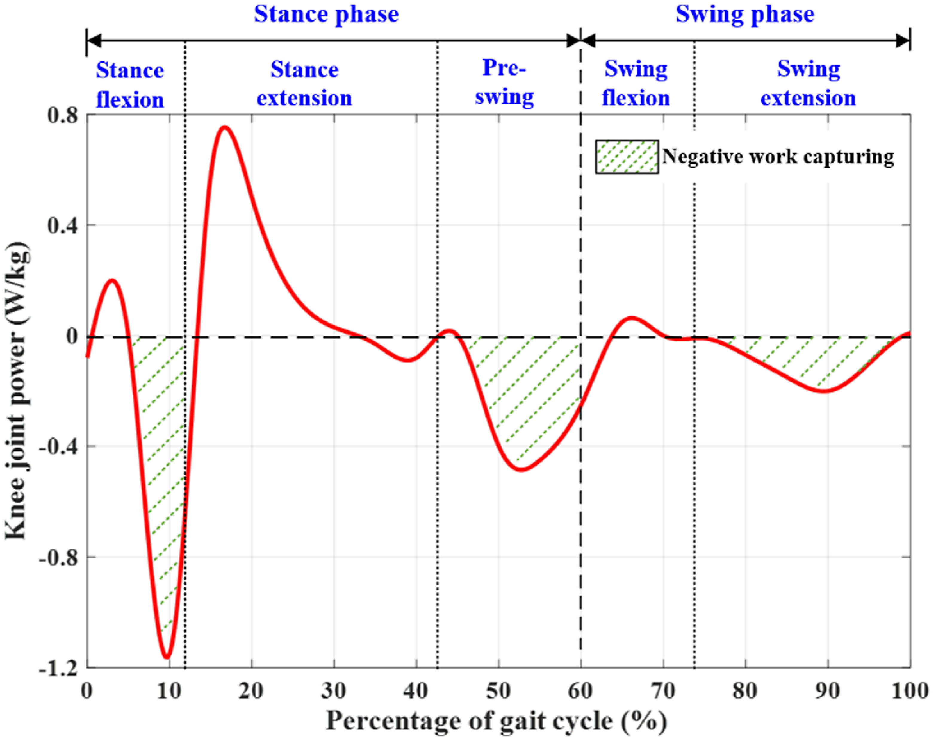
Figure 3. Joint power of the human knee in a normal gait cycle. The negative work can be generated from the knee motion in the stance flexion, pre-swing, and swing extension stages.
It can be seen from Fig. 3 that during most of the time of a gait cycle, the knee joint performs negative work with considerable power, which makes the knee joint a good source of negative work capturing. A human knee joint behaves like a spring in the stance flexion stage. In the swing phase, the knee joint torque and power tend to zero, which indicates that the knee muscle activities are not obvious during this phase. However, the knee angular velocity is very large during the swing extension stage, and a large amount of power can be produced by the knee energy harvester through a transmission mechanism during this stage. In this study, the knee exoskeleton is developed to capture the negative work from the wearer’s knee motion in the stance flexion, pre-swing, and swing extension stages, as depicted in Fig. 3.
3. Hardware Design of Knee Exoskeleton
In this study, a knee exoskeleton is proposed to capture the negative work from the wearer’s knee motion during walking, and the electrical power produced by the exoskeleton has the potential to power portable electronic devices. The exoskeleton is attached to the wearer’s thigh and shank, and it is primarily composed of a shank brace, a thigh brace, a left one-way transmission mechanism, a right one-way transmission mechanism, and a front transmission mechanism, as depicted in Fig. 4(a). The left one-way transmission mechanism is designed at the left side of the exoskeleton to capture the negative work from the wearer’s knee motion in the stance phase. The right one-way transmission mechanism is designed at the right side of the exoskeleton to capture the negative work from the wearer’s knee motion in the swing phase. The front transmission mechanism is designed at the front of the exoskeleton, and it is responsible for transferring the mechanical energy output from the left and right one-way transmission mechanisms to the generator. A prototype of the exoskeleton is fabricated, and it weighs approximately 1.24 kg, as depicted in Fig. 4(b). The main components of the exoskeleton are fabricated using the 3D printing technology. A brushless direct current motor (EC32 Flat, Maxon) is selected as the generator, and a planetary gearbox (GP32A, Maxon) is selected to amplify the angular velocity from the wearer’s knee joint to the generator.

Figure 4. Developed knee exoskeleton. The exoskeleton is primarily composed of a shank brace, a thigh brace, a left one-way transmission mechanism, a right one-way transmission mechanism, and a front transmission mechanism. (a) Mechanical structure of the knee exoskeleton. (b) Prototype of the knee exoskeleton.
The thigh and shank braces are connected through two transmission shafts, as shown in Fig. 5(a). A U-shaped upper fixed frame is designed at the front of the thigh brace in an integrated manner, and a thigh strap is connected to the back of the upper fixed frame. A U-shaped lower fixed frame is designed at the front of the shank brace in an integrated manner, and a shank strap is connected to the back of the lower fixed frame. The traditional rod-shaped design of the support frame is not adopted. In this study, the thigh and shank braces are designed with curved surfaces considering the ergonomics, which conforms to the human body curve and improves the wearing comfort of the exoskeleton.

Figure 5. Mechanical structure of the key modules of the knee exoskeleton. (a) Thigh and shank braces. (b) Left one-way transmission mechanism. (c) Right one-way transmission mechanism. (d) Front transmission mechanism.
The left one-way transmission mechanism mainly consists of a transmission shaft, a short shaft, a left rack, a gear turntable, a ratchet disk, two pawls, and five gears (namely, the gear A1, gear B1, gear C1, gear D1, and gear E1), as shown in Fig. 5(b). The left rack rotates synchronously with the transmission shaft. When the shank brace rotates relative to the thigh brace, it will drive the transmission shaft to rotate and, hence, drive the left rack to rotate synchronously. The structure of the left rack is divided into a rod part and an internal gear part. The rod part is connected to the transmission shaft, and the internal gear part engages with the gear A1. The function of the designed left rack is similar to that of a switch. The sector angle and radius of the internal gear part of the left rack are determined by the maximum angle of the wearer’s knee joint in the stance phase. The left rack is engaged with the gear A1 when the wearer’s knee angle is less than the maximum angle in the stance phase; otherwise, the left rack is disengaged with the gear A1. The gear A1, short shaft, and gear B1 rotate synchronously. The gear turntable is divided into a gear part and a turntable part. The gear B1 is engaged with the gear part of the gear turntable. The turntable part is a shuttle structure with pawls designed at both ends of the turntable part. The pawls are engaged with the ratchet disk when the wearer’s knee joint angle increases in the stance phase, and hence, the rotation of the gear turntable drives the rotation of the ratchet disk. When the knee joint angle decreases in the stance phase, the pawls are disengaged with the ratchet disk. The ratchet disk rotates synchronously with the gear C1. The gear C1, gear D1, and gear E1 form a left-side gear train, which transfers the mechanical energy to the left gear shaft of the front transmission mechanism. Therefore, the left one-way transmission mechanism is able to recognize the wearer’s gait stages, and the negative work from the wearer’s knee motion in the stance flexion and pre-swing stages is captured, as shown in Fig. 6.
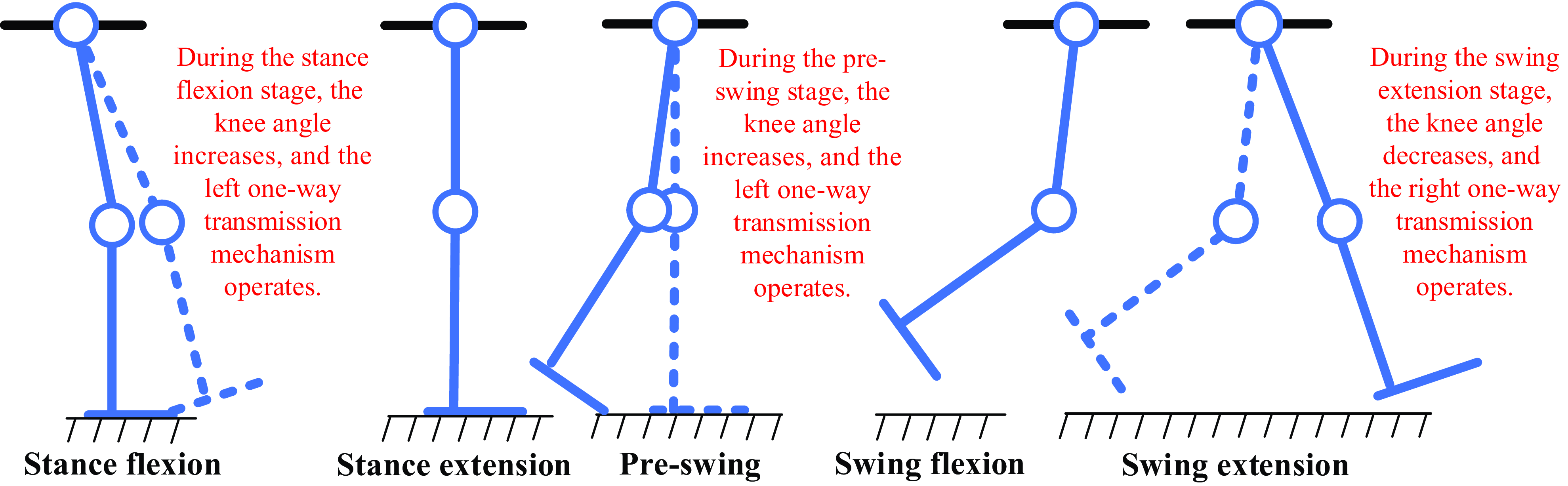
Figure 6. Negative work capturing during the stance flexion, pre-swing, and swing extension stages of a gait cycle. During the stance flexion, pre-swing, and swing extension stages, the leg in the dashed line is at the beginning of this stage, and the leg in the solid line is at the end of this stage.
The right one-way transmission mechanism is primarily composed of a transmission shaft, a short shaft, a right rack, a gear turntable, a ratchet disk, two pawls, and six gears (namely, the gear A2, gear B2, gear C2, gear D2, gear E2, and gear F2), as shown in Fig. 5(c). The structure of the right one-way transmission mechanism is similar to that of the left one-way transmission mechanism. The difference is that the formed right-side gear train has one more gear, namely, the gear F2, and hence, the right gear shaft of the front transmission mechanism can rotate in the same direction as the left gear shaft with the mechanical energy received. In addition, the sector angle and radius of the internal gear part of the right rack are determined by the maximum angle of the wearer’s knee joint in the stance extension stage. The right rack is engaged with the gear A2 when the wearer’s knee angle is larger than the maximum angle in the stance extension stage; otherwise, the right rack is disengaged with the gear A2. Similarly, the pawls are engaged with the ratchet disk when the wearer’s knee joint angle decreases in the swing phase; otherwise, the pawls are disengaged with the ratchet disk. Therefore, the right one-way transmission mechanism is able to recognize the wearer’s gait stages, and the negative work from the wearer’s knee motion in the swing extension stage is captured, as shown in Fig. 6.
The front transmission mechanism mainly includes a left gear shaft, a right gear shaft, 2 bearing supports, 2 pawl turntables, 12 pawls, a ratchet wheel, a planetary gearbox, and a generator, as shown in Fig. 5(d). The gear E1 and gear F2 are one of the gears of the gear trains in the left and right one-way transmission mechanisms, respectively, and their rotations drive the synchronous rotations of the left gear shaft and right gear shaft, respectively. The pawl turntable rotates synchronously with the gear shaft. The pawls are designed on the pawl turntable to drive the ratchet wheel, and hence, both the rotations of the left and right gear shafts can lead to the rotation of the ratchet wheel. The left-side and right-side gear trains make the rotation directions of the left and right gear shafts the same. Thus, the wearer’s knee flexion and knee extension can be converted into the generator unidirectional rotation. Due to the inertia of the generator when changing its rotation direction, the unidirectional rotation of the generator during the operation of the exoskeleton can improve the exoskeleton robustness and avoid affecting the wearer’s gait.
4. Modeling and Analysis of Energy Harvesting
The rotational input from the wearer’s knee joint to the knee exoskeleton is accelerated through the designed gear trains and the planetary gearbox connected to the generator. The designed left and right one-way transmission mechanisms of the exoskeleton are used to capture the negative work from the wearer’s knee motion in the stance and swing phases, respectively, and they are designed with different transmission ratios. Regarding the left one-way transmission mechanism, five gears, a rack, and a gear turntable are designed, and the numbers of their teeth are
 $z_{1},z_{1},z_{2},z_{3},z_{3},z_{4},z_{3}$
. For the right one-way transmission mechanism, six gears, a rack, and a gear turntable are designed, and the numbers of their teeth are
$z_{1},z_{1},z_{2},z_{3},z_{3},z_{4},z_{3}$
. For the right one-way transmission mechanism, six gears, a rack, and a gear turntable are designed, and the numbers of their teeth are
 $z_{1},z_{3},z_{3},z_{3},z_{3},z_{3},z_{5},z_{3}$
. Thus, the transmission ratio of the whole system of the exoskeleton can be obtained as follows:
$z_{1},z_{3},z_{3},z_{3},z_{3},z_{3},z_{5},z_{3}$
. Thus, the transmission ratio of the whole system of the exoskeleton can be obtained as follows:
 \begin{equation}i_{1}=i_{g1}i_{p}=\frac{z_{1}^{2}z_{2}z_{4}}{z_{2}z_{3}^{3}}i_{p}=\frac{z_{1}^{2}z_{4}}{z_{3}^{3}}i_{p}\end{equation}
 \begin{equation}i_{2}=i_{g2}i_{p}=\frac{z_{1}z_{3}^{3}z_{5}}{z_{3}^{5}}i_{p}=\frac{z_{1}z_{5}}{z_{3}^{2}}i_{p}\end{equation}
where
 $i_{1}$
represents the exoskeleton transmission ratio during the stance phase,
$i_{1}$
represents the exoskeleton transmission ratio during the stance phase,
 $i_{2}$
represents the exoskeleton transmission ratio during the swing phase,
$i_{2}$
represents the exoskeleton transmission ratio during the swing phase,
 $i_{g1}$
represents the transmission ratio of the left one-way transmission mechanism,
$i_{g1}$
represents the transmission ratio of the left one-way transmission mechanism,
 $i_{g2}$
represents the transmission ratio of the right one-way transmission mechanism, and
$i_{g2}$
represents the transmission ratio of the right one-way transmission mechanism, and
 $i_{p}$
represents the transmission ratio of the planetary gearbox.
$i_{p}$
represents the transmission ratio of the planetary gearbox.
Then, the angular velocities of the generator in the stance and swing phases can be obtained as follows:
 \begin{equation}\dot{\theta }_{g1}=i_{1}\dot{\theta }_{\text{knee}}\end{equation}
 \begin{equation}\dot{\theta }_{g2}=i_{2}\dot{\theta }_{\text{knee}}\end{equation}
where
 $\dot{\theta }_{\text{knee}}$
is the angular velocity of the wearer’s knee joint.
$\dot{\theta }_{\text{knee}}$
is the angular velocity of the wearer’s knee joint.
A back electromotive force can be produced by the rotation of the generator, which can be obtained as follows:
 \begin{equation}E_{1}=K_{V}\dot{\theta }_{g1}\end{equation}
 \begin{equation}E_{2}=K_{V}\dot{\theta }_{g2}\end{equation}
where
 $E_{1}$
and
$E_{1}$
and
 $E_{2}$
are the back electromotive forces generated during the stance phase and swing phase, respectively, and K
V
is the generator speed constant.
$E_{2}$
are the back electromotive forces generated during the stance phase and swing phase, respectively, and K
V
is the generator speed constant.
In addition, an instantaneous induced reaction torque is generated with the rotation of the generator, which can be calculated as follows:
 \begin{equation}T_{i1}=K_{T}I_{1}\end{equation}
 \begin{equation}T_{i2}=K_{T}I_{2}\end{equation}
where
 $T_{i1}$
and
$T_{i1}$
and
 $T_{i2}$
are the instantaneous induced reaction torques generated during the stance phase and swing phase, respectively, K
T
is the generator torque constant, and
$T_{i2}$
are the instantaneous induced reaction torques generated during the stance phase and swing phase, respectively, K
T
is the generator torque constant, and
 $I_{1}$
and
$I_{1}$
and
 $I_{2}$
are the currents flowing through the generator during the stance phase and swing phase, respectively.
$I_{2}$
are the currents flowing through the generator during the stance phase and swing phase, respectively.
Based on Kirchhoff’s voltage law, the back electromotive force is also equal to the sum of the electrical resistance voltage and the inductance voltage. Thus, we can obtain
 \begin{equation}E_{1}=I_{1}\left(R+R_{i}\right)+LI_{1}\dot{\theta }_{g1}\end{equation}
 \begin{equation}E_{2}=I_{2}\left(R+R_{i}\right)+LI_{2}\dot{\theta }_{g2}\end{equation}
where
 $R$
is the external electrical resistance connected to the generator,
$R$
is the external electrical resistance connected to the generator,
 $R_{i}$
is the internal electrical resistance of the generator, and
$R_{i}$
is the internal electrical resistance of the generator, and
 $L$
is the inductance of the generator.
$L$
is the inductance of the generator.
In this study, the term
 $(R+R_{i})$
is much larger than the term
$(R+R_{i})$
is much larger than the term
 $L\dot{\theta }_{g1}$
in Eq. (9) and the term
$L\dot{\theta }_{g1}$
in Eq. (9) and the term
 $L\dot{\theta }_{g2}$
in Eq. (10), and hence, the inductance of the generator is neglected. Then, the back electromotive forces
$L\dot{\theta }_{g2}$
in Eq. (10), and hence, the inductance of the generator is neglected. Then, the back electromotive forces
 $E_{1}$
and
$E_{1}$
and
 $E_{2}$
can be approximately calculated as follows:
$E_{2}$
can be approximately calculated as follows:
 \begin{equation}E_{1}=K_{V}\dot{\theta }_{g1}\approx I_{1}(R+R_{i})\end{equation}
 \begin{equation}E_{2}=K_{V}\dot{\theta }_{g2}\approx I_{2}(R+R_{i})\end{equation}
During the process of the power generation, the energy loss exists owing to the friction of the transmission mechanism and the generator heat dissipation. The mechanical transmission efficiency is mainly determined by the planetary gearbox and the designed gear trains and ratchet pawl mechanisms, and it can be expressed as follows:
 \begin{equation}\eta _{m}=\eta _{p}\eta _{gt}\eta _{r}\end{equation}
where
 $\eta _{p}$
,
$\eta _{p}$
,
 $\eta _{gt}$
, and
$\eta _{gt}$
, and
 $\eta _{r}$
are the efficiencies of the planetary gearbox, gear trains, and ratchet pawl mechanisms, respectively.
$\eta _{r}$
are the efficiencies of the planetary gearbox, gear trains, and ratchet pawl mechanisms, respectively.
During the stance phase, the corresponding mechanical transmission efficiency is approximately 42.5% (mainly including a planetary gearbox, a left-side gear train, and two ratchet pawl mechanisms), and the corresponding mechanical transmission efficiency during the swing phase is approximately 37.4% (mainly including a planetary gearbox, a right-side gear train, and two ratchet pawl mechanisms). Regarding the generator heat dissipation, the generator inductance is considerably small and is neglected in this study. Thus, the electrical efficiency of the power generation can be calculated as follows:
 \begin{equation}\eta _{e}=\frac{R}{R+R_{i}}\end{equation}
Then, the power generation efficiency of the designed knee exoskeleton can be approximately calculated as follows:
 \begin{equation}\eta =\eta _{m}\eta _{e}\end{equation}
The external electrical resistance is designed to be equal to the internal electrical resistance of the generator to obtain a maximum power generation, and hence, an electrical efficiency of approximately 50% can be obtained. Thus, the power generation efficiencies of the exoskeleton during the stance phase and swing phase are approximately 21.2% and 18.7%, respectively. Finally, the effective power captured from the wearer’s knee motion in the stance and swing phases can be calculated as follows:
 \begin{equation}P_{e1}=I_{1}^{2}R=\frac{K_{V}^{2}i_{1}^{2}\dot{\theta }_{\text{knee}}^{2}R}{(R{+R_{i}})^{2}}\end{equation}
 \begin{equation}P_{e2}=I_{2}^{2}R=\frac{K_{V}^{2}i_{2}^{2}\dot{\theta }_{\text{knee}}^{2}R}{(R{+R_{i}})^{2}}\end{equation}
The designed gear trains and planetary gearbox serve as an angular velocity multiplier in this study. Thus, they can amplify the induced reaction torque, which can assist the deceleration of the wearer’s knee joint. Considering the mechanical transmission efficiency, the torques generated to assist the wearer’s knee joint deceleration in the stance and swing phases can be obtained using Eqs. (18) and (19), respectively. It can be seen that with an increased angular velocity of the wearer’s knee joint, the generated power and torque can be increased:
 \begin{equation}T_{g1}=\frac{i_{1}T_{i1}}{\eta _{m1}}=\frac{K_{T}K_{V}i_{1}^{2}\dot{\theta }_{\text{knee}}}{\eta _{m1}(R+R_{i})}\end{equation}
 \begin{equation}T_{g2}=\frac{i_{2}T_{i2}}{\eta _{m2}}=\frac{K_{T}K_{V}i_{2}^{2}\dot{\theta }_{\text{knee}}}{\eta _{m2}(R+R_{i})}\end{equation}
where
 $\eta _{m1}$
and
$\eta _{m1}$
and
 $\eta _{m2}$
are the mechanical transmission efficiencies of the exoskeleton in the stance and swing phases, respectively.
$\eta _{m2}$
are the mechanical transmission efficiencies of the exoskeleton in the stance and swing phases, respectively.
5. Experiments and Results
Walking experiments were performed to verify the effectiveness of the developed knee exoskeleton. Eight participants (healthy males, 24 ± 3 years old, weight 70 ± 11 kg, height 1.72 ± 0.07 m) were recruited in the human trials. The developed knee exoskeleton was tested under the following three conditions: (1) walking on a treadmill without the exoskeleton (NO-EXO), (2) walking on a treadmill with the exoskeleton in a not-working condition (EXO-OFF), and (3) walking on a treadmill with the exoskeleton in a working condition. Before the experiments were conducted, the participants walked on the treadmill while wearing the exoskeleton in the not-working condition for 15 min to facilitate the adaptation to the added weight of the exoskeleton to their legs. The experimental setup is illustrated in Fig. 7. In the experiments, the treadmill was used for the accurate walking speed control of the participants. To obtain the power produced by the exoskeleton, we utilized an oscilloscope to measure the voltage of the external electrical resistance. A wired electromyographic (EMG) system was utilized to collect the rectus femoris and semitendinosus activities of the participants. Besides, we used a motion capture system to collect the participants’ knee joint angles under the three walking conditions.

Figure 7. Experimental setup of the walking experiments. The treadmill is used to control the walking speed. The oscilloscope is used to measure the voltage of the external electrical resistance. The EMG system is used to collect the muscles activities. The motion capture system is used to collect the participants’ knee joint angles.
In the first group of walking experiments, the participants walked on the treadmill at a speed of 4.5 km/h while not wearing the knee exoskeleton. Each participant conducted three walking trials, and a 5-min break was provided for each participant between the consecutive trials. In addition, each walking trial lasted three min, and the data measured in the last minute were utilized to evaluate the performance of the exoskeleton. In the second group of walking experiments, the participants also walked on the treadmill at a speed of 4.5 km/h while wearing the knee exoskeleton, and the exoskeleton was in the not-working condition. In the third group of walking experiments, the participants wore the exoskeleton and walked on the treadmill at a speed of 4.5 km/h, and the exoskeleton was in the working condition. The negative work captured by the exoskeleton from the participant’s knee motion was recorded by the oscilloscope. In the second and third groups of walking experiments, the participants repeated the walking process of the first group of walking experiments, respectively.
Under each walking condition, 24 walking trials in total were conducted for the 8 participants, and the experimental data measured in the 24 walking trials were averaged. The average of the power produced by the exoskeleton and the average of the participants’ knee joint angles and muscle activities over the eight participants under the three walking conditions were used to validate the effectiveness of the exoskeleton. The testing results are shown in Figs. 8–10. The power produced by the exoskeleton in the third group of walking experiments is shown in Fig. 8, which is calculated based on the measured voltage of the external electrical resistance. The participants’ knee joint angles in the three groups of walking experiments are shown in Fig. 9, and the rectus femoris and semitendinosus activities of the participants in the three groups of walking experiments are shown in Fig. 10.
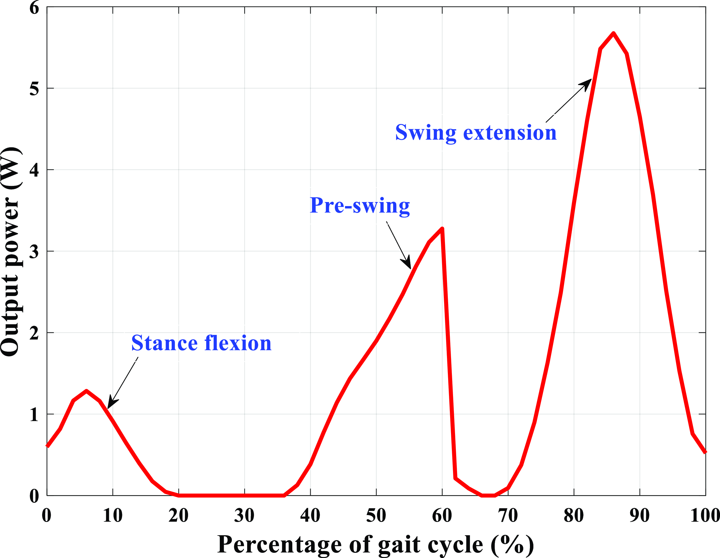
Figure 8. Power produced by the knee exoskeleton. The exoskeleton captures the negative work from the wearer’s knee motion during the stance flexion, pre-swing, and swing extension stages of a gait cycle.

Figure 9. Knee joint angles of the participants in the three groups of walking experiments. p < 0.05 indicates statistically significant difference, and p > 0.05 indicates no statistically significant difference. (a) Knee joint trajectories. (b) Statistical analysis results of the overall knee joint trajectories.

Figure 10. Muscle activities of the rectus femoris and semitendinosus of the participants in the three groups of walking experiments. p < 0.05 indicates statistically significant difference, and p > 0.05 indicates no statistically significant difference. (a) Rectus femoris activities. (b) Statistical analysis results of the overall rectus femoris activities. (c) Semitendinosus activities. (d) Statistical analysis results of the overall semitendinosus activities.
The raw EMG signals collected in the experiments were low-pass filtered at 10 Hz using a second-order Butterworth filter, full-wave rectified, and high-pass filtered at 20 Hz using a second-order Butterworth filter, and the sampling frequency was 1000 Hz. To detect the statistically significant differences in the knee joint angles and muscle activities of the participants in the three groups of walking experiments, one-way repeated measures analyses of variance was conducted. The statistical analyses were performed in the IBM SPSS software with the significance level set at α = 0.05.
6. Discussions
The proposed knee exoskeleton can capture the negative work from the wearer’s knee motion during all the stages that the negative work is performed of a gait cycle and realize the power generation function while decreasing the muscle activities of the wearer. The electrical energy produced by the exoskeleton has the potential to be utilized in charging a battery and powering some portable electronic devices. The effectiveness of the proposed exoskeleton is demonstrated by analyzing the recycled energy of the exoskeleton and the knee joint angles and rectus femoris and semitendinosus activities of the participants collected in the walking experiments.
One-way transmission mechanisms are designed to transmit the mechanical energy of the exoskeleton, and the angular velocities of the one-way transmission mechanisms are determined by the wearer’s knee angular velocities. Thus, the amount of energy captured from the wearer’s knee motion is positively correlated with the angular velocity of the wearer’s knee joint. During the stance flexion and swing extension stages, the angular velocity of the participant’s knee joint increases first and then decreases, and hence, the corresponding output power of the exoskeleton also increases first and then decreases, as shown in Fig. 8. During the pre-swing stage, the exoskeleton also works, and the angular velocity of the participant’s knee joint continues increasing. However, the exoskeleton does not work during the swing flexion stage. Thus, the corresponding power produced by the exoskeleton continues increasing during the pre-swing stage and then decreases sharply to zero during the swing flexion stage. In a normal gait cycle, the human knee angular velocities during the stance flexion, pre-swing, and swing extension stages increase in sequence, and hence, the output powers of the exoskeleton also increase in sequence during the three stages. Based on the power produced by the exoskeleton (Fig. 8) in the third group of walking experiments, we can see that the proposed exoskeleton can capture the negative work from the participant’s knee motion during the stance flexion, pre-swing, and swing extension stages, covering all the stages that the negative work is performed during walking. The peak and average output powers of the exoskeleton during the stance flexion stage are approximately 1.28 ± 0.18 and 0.80 ± 0.07 W, respectively. During the pre-swing stage, the peak and average output powers of the exoskeleton are approximately 3.28 ± 0.25 and 1.78 ± 0.13 W, respectively, and the peak and average output powers of the exoskeleton during the swing extension stage are approximately 5.68 ± 0.23 and 2.92 ± 0.12 W, respectively. In addition, the average power produced by the exoskeleton during a gait cycle is approximately 1.45 ± 0.13 W.
With the knee joint trajectories (Fig. 9(a)) obtained in the three groups of walking experiments, it can be seen that the knee joint trajectories in the second and third groups of walking experiments are consistent with that of the first group of experiments. This implies that the additional weight of the proposed exoskeleton on the participants has little effect on their gaits. Based on the statistical analysis results of the overall knee joint trajectories of the participants (Fig. 9(b)), no statistically significant difference in the participants’ knee joint trajectories is observed in the walking experiments conducted under the three conditions (NO-EXO condition vs. EXO-OFF condition: p = 0.414 > 0.05; NO-EXO condition vs. EXO-ON condition: p = 0.778 > 0.05; EXO-OFF condition vs. EXO-ON condition: p = 0.823 > 0.05).
The human rectus femoris is primarily responsible for the knee extension in a gait cycle, and it can also help for the knee flexion by performing negative work in the late stance phase. From the experimental results in Fig. 10(a), it can be observed that in comparison with those (157.59 ± 5.49 and 108.71 ± 9.57 μV, respectively) of the first group of walking experiments, the peak (167.30 ± 10.62 μV) and average (112.57 ± 7.34 μV) rectus femoris activities during a gait cycle in the second group of walking experiments are increased by 6.16% (p = 0.075 > 0.05, without statistically significant difference) and 3.55% (p = 0.668 > 0.05, without statistically significant difference), respectively, and the peak (149.52 ± 7.10 μV) and average (104.71 ± 6.12 μV) rectus femoris activities during a gait cycle in the third group of walking experiments are decreased by 5.12% (p = 0.217 > 0.05, without statistically significant difference) and 3.68% (p = 0.413 > 0.05, without statistically significant difference), respectively. In addition, the peak and average rectus femoris activities during a gait cycle in the third group of walking experiments are decreased by 10.63% (p = 0.008 < 0.05, with statistically significant difference) and 6.98% (p = 0.139 > 0.05, without statistically significant difference), respectively, in comparison with those of the second group of walking experiments.
The human semitendinosus is mainly responsible for the knee flexion in a gait cycle, and it can also help for the knee extension and slowing down of the lower leg by performing negative work in the swing phase. It can be seen from Fig. 10(c) that in comparison with those (146.63 ± 5.91 and 82.13 ± 5.56 μV, respectively) of the first group of walking experiments, the peak (160.25 ± 8.69 μV) and average (85.03 ± 7.62 μV) semitendinosus activities during a gait cycle in the second group of walking experiments are increased by 9.29% (p = 0.042 < 0.05, with statistically significant difference) and 3.54% (p = 0.670 > 0.05, without statistically significant difference), respectively, and the peak (142.12 ± 8.46 ;μV) and average (79.34 ± 7.09 μV) semitendinosus activities during a gait cycle in the third group of walking experiments are decreased by 3.08% (p = 0.604 > 0.05, without statistically significant difference) and 3.40% (p = 0.588 > 0.05, without statistically significant difference), respectively. In addition, we can see that the peak and average semitendinosus activities in a gait cycle in the third group of walking experiments are decreased by 11.31% (p = 0.013 < 0.05, with statistically significant difference) and 6.69% (p = 0.216 > 0.05, without statistically significant difference), respectively, in comparison with those of the second group of walking experiments.
The overall muscle activities of the rectus femoris and semitendinosus of the participants in the three groups of walking experiments are analyzed, as shown in Figs. 10(b) and (d). It can be seen that no statistically significant differences in the rectus femoris activities are observed between the first group of walking experiments and each of the second (p = 0.315) and third (p = 0.286) groups of walking experiments. However, statistically significant difference in the rectus femoris activities is observed between the second and third groups of walking experiments (p = 0.009). Regarding the semitendinosus, no statistically significant differences are observed between the first group of walking experiments and each of the second (p = 0.419) and third (p = 0.446) groups of walking experiments. However, statistically significant difference in the semitendinosus activities is observed between the second and third groups of walking experiments (p = 0.036). On the whole, the experimental results demonstrate that the additional weight of the exoskeleton on the participants has little effect on the knee muscle activities of the participants, and the exoskeleton can assist the participants’ knee joints to perform negative work to achieve walking assistance.
The proposed knee exoskeleton is compared with the other existing exoskeletons (energy harvesters), and the comparison results are given in Table I. In comparison with the other studies that can only recycle the negative work from the wearer’s knee motion during two stages of a gait cycle, the exoskeleton developed in this study can capture the negative work during three stages (namely, the stance flexion, pre-swing, and swing extension) of a gait cycle, which can produce more electrical energy and can assist the deceleration of the wearer’s knee joint. In addition to recycling the negative work from the wearer’s knee motion, some amount of positive work is also recycled in most of the other studies, and it can generate more power. However, the wearer’s metabolic cost can be increased by recycling the positive work. In this study, only the negative work can be recycled from the wearer’s knee motion by the exoskeleton. It can be seen from Table I that the developed knee exoskeleton is a little heavy in comparison with the other existing exoskeletons (energy harvesters) in the current study. The proposed exoskeleton will be optimized to make the structure more compact and lighter in our future studies.
Table I. Comparison between the developed knee exoskeleton and other studies.

KEH, knee energy harvester; KE, knee exoskeleton; KAE, knee-ankle exoskeleton; /, not applicable.
Other limitations of our present study are as follows. The power produced by the proposed knee exoskeleton is measured, and it is not utilized in practical applications in our current study. In future studies, we will design a power management circuit to power portable electronic devices or charge a battery with the negative work captured from the wearer’s knee motion. In addition, the wearer’s soft tissue will have some deformations during the normal walking, which may lead to a slight misalignment between the exoskeleton and the human body. In future studies, we will adopt some smart materials (such as the shape memory alloy and/or the shape memory polymer) employing 3D printing to create 4D printing technology for the development of the knee exoskeleton and, hence, to improve the connection between the wearer and the exoskeleton. Moreover, more human trials will be performed to further validate the effectiveness of the proposed knee exoskeleton in future studies, and the metabolic cost of the participants will be evaluated by measuring the CO2 production and O2 consumption continuously through wearing a face mask connected to a gas analysis system.
7. Conclusions
In this paper, we presented the design and testing of a knee exoskeleton for energy recycling during all the stages that the negative work was performed by the wearer’s knee joint during walking. The human knee joint biomechanics, hardware design of the exoskeleton, and modeling and analysis of the energy harvesting system were described. With the front transmission mechanism, the left one-way transmission mechanism could capture the negative work from the wearer’s knee motion in the stance flexion and pre-swing stages, and the right one-way transmission mechanism could capture the negative work in the swing extension stage. A prototype of the knee exoskeleton was fabricated, and experiments were performed to evaluate the performance of the proposed exoskeleton. The testing results validated that when wearing the exoskeleton at a walking speed of 4.5 km/h, the exoskeleton could produce an average and maximum electrical power of 1.45 ± 0.13 and 5.68 ± 0.23 W, respectively, during a gait cycle. In addition, reductions of 3.68% and 3.40% of the average rectus femoris and semitendinosus activities were observed, respectively, during a gait cycle.
Acknowledgments
The authors thank Chengwang Zheng, Xiang Ni, Lei Zhou, Ruijin Wang, Yadong Wu, and Kenan Ye for supporting in the experiments.
Author contributions
Bing Chen and Bin Zi conceived and designed the study. Jialiang Tan conducted data gathering. Chenpu Shi performed statistical analyses. Bing Chen and Jialiang Tan wrote the article.
Financial support
This work is supported by the National Natural Science Foundation of China (Grant Nos. 52275242, 51925502, and 72188101).
Competing interests
The authors declare no competing interest exist.


