


1. Introduction
Flying insects, e.g. bees, flies and moths, are remarkable flyers in nature, considering their miniature bodies, stable and sustained hovering capability, and agile manoeuvres (Dudley Reference Dudley2002). Researchers have been focusing on understanding the physics of the augmented lift generation of flying insects for decades, and several unsteady mechanisms have been proposed (Sane Reference Sane2003; Sun Reference Sun2014; Chin & Lentink Reference Chin and Lentink2016). The absence of stall, which is attributed to the formation and stable attachment of a leading-edge vortex (LEV), can produce a sustained high lift on a flapping wing (Ellington et al. Reference Ellington, Van Den Berg, Willmott and Thomas1996). A similar phenomenon is also observed on unidirectionally revolving wings at high angles of attack  $\alpha$ (Wu & Sun Reference Wu and Sun2004; Poelma, Dickson & Dickinson Reference Poelma, Dickson and Dickinson2006; Garmann, Visbal & Orkwis Reference Garmann, Visbal and Orkwis2013; Carr, DeVoria & Ringuette Reference Carr, DeVoria and Ringuette2015; Jardin Reference Jardin2017; Smith et al. Reference Smith, Rockwell, Sheridan and Thompson2017; Chen, Wu & Cheng Reference Chen, Wu and Cheng2019, Reference Chen, Wu and Cheng2020; Werner et al. Reference Werner, Chung, Wang, Liu, Cimbala, Dong and Cheng2019) and on small-scale wind turbines (Lentink & Dickinson Reference Lentink and Dickinson2009; Zhao et al. Reference Zhao, Yan, Li and Wang2022). However, no attached LEV is observed on steady-state translating wings at a high
  $\alpha$ and comparable range of Reynolds number
  $\textit {Re}$ (Dickinson & Gotz Reference Dickinson and Gotz1993; Chen, Colonius & Taira Reference Chen, Colonius and Taira2010), suggesting that the revolving motion and its associated unique three-dimensional (3-D) effects are responsible for the LEV stability. Therefore, numerous studies have investigated the 3-D vortex structures and underlying vorticity dynamics on revolving wings, aiming at elucidating the mechanisms for the LEV stability.
One of the earliest attempts to understand the LEV stability was conducted by Ellington and his colleagues, who examined experimentally the flow patterns on hawkmoth wings (Ellington et al. Reference Ellington, Van Den Berg, Willmott and Thomas1996) and bio-mimicry model wings (Van Den Berg & Ellington Reference Van Den Berg and Ellington1997). They concluded that the vorticity convection due to spanwise flow (tip-ward) can transport the vorticity inside the LEV towards the wingtip, therefore contributing to LEV stability. They further showed that the tip-ward spanwise flow can be generated by the spanwise pressure gradient, which was supported by following research (Jardin & David Reference Jardin and David2014). However, this mechanism was questioned by some other experimental and numerical research (Birch & Dickinson Reference Birch and Dickinson2001; Shyy & Liu Reference Shyy and Liu2007; Cheng et al. Reference Cheng, Sane, Barbera, Troolin, Strand and Deng2013), in which no significant spanwise flow was observed alongside a stable LEV when  $\textit {Re}$ is of the order of 100. It is further suggested by both Birch & Dickinson (Reference Birch and Dickinson2001) and Shyy & Liu (Reference Shyy and Liu2007) that the mechanisms of LEV stability can be dependent on
  $\textit {Re}$, and the spanwise vorticity convection may be a minor contributor to LEV stability at
  $\textit {Re}$ close to 100.
Alternatively, Lentink & Dickinson (Reference Lentink and Dickinson2009) proposed a rotational-acceleration-based mechanism to explain the stable LEV attachment and augmented lift. They proposed that the centrifugal and Coriolis accelerations are responsible for LEV stability, and since they are inversely proportional to the aspect ratio (AR), the low-AR natural flyers and revolving wings can maintain strong rotational accelerations and a stable LEV. This is supported by a survey of AR in natural flyers (Chin & Lentink Reference Chin and Lentink2016), the scaling analysis of Navier–Stokes equations (Lentink & Dickinson Reference Lentink and Dickinson2009) and experiments of dynamically scaled revolving wings (Kruyt et al. Reference Kruyt, Van Heijst, Altshuler and Lentink2015). To further unravel the role of rotational accelerations in LEV stability, Jardin & David (Reference Jardin and David2015) artificially adjusted the centrifugal and Coriolis accelerations in their simulations, and a breakdown of both LEV stability and associated high lift generation is observed when the Coriolis acceleration is removed. Jardin (Reference Jardin2017) concluded in his following research that the Coriolis acceleration is the major contributor to LEV stability at  $\textit {Re} > 200$. Werner et al. (Reference Werner, Chung, Wang, Liu, Cimbala, Dong and Cheng2019) proposed another mechanism related to Coriolis acceleration. They associated the tangential Coriolis acceleration to the radial tilting of planetary vorticity, i.e. PVT
 $_{r}$, and thereafter regarded PVT
 $_{r}$ as a universal contributor to LEV stability with
  $\textit {Re}=110\unicode{x2013}1400$ and
  $\textit {AR}=3\unicode{x2013}7$. In contrast to these studies, Garmann & Visbal (Reference Garmann and Visbal2014) found that the normal component of the Coriolis acceleration tends to move the LEV away from the wing, thus questioning the direct effects of Coriolis acceleration.
Although the above two major mechanisms for LEV stability (i.e. those due to spanwise flow or rotational accelerations) were usually studied separately, some studies showed the connections between Coriolis acceleration and the tip-ward spanwise flow (Lentink & Dickinson Reference Lentink and Dickinson2009; Jardin Reference Jardin2017). The Coriolis acceleration is suggested to drive the tip-ward spanwise flow (mostly within the LEV region), therefore the stable LEV is achieved due to spanwise vorticity convection. This is associated with the first mechanism since the ultimate mechanism that removes the vorticity inside the LEV is the spanwise vorticity convection, except that the formation of tip-ward spanwise flow is different. Besides, additional studies also proposed that the LEV stability can be maintained by downwash effects (Birch & Dickinson Reference Birch and Dickinson2001; Cheng et al. Reference Cheng, Sane, Barbera, Troolin, Strand and Deng2013) or vorticity annihilation (Wojcik & Buchholz Reference Wojcik and Buchholz2014). Birch & Dickinson (Reference Birch and Dickinson2001) placed fences along the leading edge of a revolving wing ( $\textit {Re}=110$) to block the spanwise flow. Surprisingly, the LEV remains attached without the spanwise flow. Therefore, they suggested that the tip-vortex-induced downwash can contribute to LEV stability by reducing the effective angle of attack. Moreover, Wojcik & Buchholz (Reference Wojcik and Buchholz2014) suggested that the oppositely signed vorticity between the LEV and the wing surface can balance the vorticity inside the LEV via an entrainment, which is regarded as the vorticity annihilation.
Our previous work on the vorticity dynamics within the LEV suggested a novel vortex-tilting-based mechanism that leads to a  $180^{\circ }$ reversal of the local radial vorticity component (Chen et al. Reference Chen, Wang, Zhou, Wu and Cheng2022), thus contributing to the LEV stability on revolving wings. This mechanism was named previously the radial–tangential vorticity balance; however, it is renamed in this work as dual-stage radial–tangential vortex tilting (DS-VT
 $_{r-t}$). In Chen et al. (Reference Chen, Wang, Zhou, Wu and Cheng2022), the underlying tangential vorticity transport of DS-VT
 $_{r-t}$ has not been fully quantified or discussed, and the effects of
  $\textit {Re}$, AR and Ro on this novel mechanism are not fully investigated. It has been concluded that the LEV dynamics and its stabilizing mechanisms depend strongly on these dimensionless parameters. For example, Harbig, Sheridan & Thompson (Reference Harbig, Sheridan and Thompson2013) defined a span-based Reynolds number
  $\textit {Re}_b$ to examine the coupled effects of
  $\textit {Re}$ and AR on the LEV stability of fruit fly wings, which led to improved prediction of LEV bursting. Later, Lee, Lua & Lim (Reference Lee, Lua and Lim2016) investigated numerically four degrees of coupling between AR and Ro in low
  $\textit {Re}$ revolving wings. They found that increasing AR can alleviate the wingtip effects on the LEV (beneficial to lift generation), while increasing Ro can reduce the LEV intensity (detrimental to lift generation). Moreover, Jardin & Colonius (Reference Jardin and Colonius2018) proposed an optimal AR (for wings revolving around their roots) that maximizes the region of stable LEV along the span. Taking the wingspan as the characteristic length, Bhat et al. (Reference Bhat, Zhao, Sheridan, Hourigan and Thompson2019a,Reference Bhat, Zhao, Sheridan, Hourigan and Thompsonb) decoupled the effects of
  $\textit {Re}$, AR and Ro on the LEV stability of revolving wings without further examining the underlying vorticity dynamics.
Continuing the work of our previous studies on LEV dynamics (Chen et al. Reference Chen, Wu and Cheng2019, Reference Chen, Wu and Cheng2020, Reference Chen, Wang, Zhou, Wu and Cheng2022), this research is to examine systematically the mechanism of DS-VT $_{r-t}$ and to elucidate its role in regulating the local radial vorticity component and in LEV stability under various
  $\textit {Re}$, AR and Ro. To the authors’ best knowledge, DS-VT
 $_{r-t}$ is the first proposed mechanism for LEV stability that involves a negative feedback loop, which is often a requirement for stability in dynamical systems (Åström & Murray Reference Åström and Murray2021). Based on the potential flow theory, Minotti & Speranza (Reference Minotti and Speranza2005) analysed the LEV stability and proposed an equilibrium condition that also inferred a feedback mechanism, while no evidence of vorticity dynamics was provided and this feedback mechanism was not identified. In this research, the flow data are simulated by an in-house computational fluid dynamics solver, and the analysis of vorticity dynamics is governed by the vorticity transport equation in a co-rotating frame. The wing geometry and kinematics, numerical solver, meshing procedure and validation are introduced in § 2. The constant ratio of radial and tangential vorticity components within the stable LEV is described in § 3.1, and the vorticity dynamics of DS-VT
 $_{r-t}$ is explained in § 3.2. The effects of
  $\textit {Re}$, AR and Ro are then discussed in §§ 3.3 and 3.4. Conclusions are provided in § 4.
2. Methodology
2.1. Problem set-up and numerical simulation
In this research, the revolving wing is simplified as a flat rectangular plate, which has been employed widely in previous works (Garmann & Visbal Reference Garmann and Visbal2014; Carr et al. Reference Carr, DeVoria and Ringuette2015; Smith et al. Reference Smith, Rockwell, Sheridan and Thompson2017; Chen et al. Reference Chen, Wang, Zhou, Wu and Cheng2022). Given a fixed wing thickness ( $h$), the dimensionless parameters of wing geometry are aspect ratio (AR) and root cutout (
 $r_{0}$, also known as root cutoff). Here, AR is defined as the ratio of wingspan (
 $b$) and chord (
 $c$), and
  $r_{0}$ represents the chord-normalized root cutout from the centre of rotation (CoR), as shown in figure 1(a). The Rossby number (Ro), representing the ratio of advection and Coriolis accelerations, is therefore defined as
 \begin{equation} \textit{Ro}=R_g/c=\frac{1}{c}\,\sqrt{\int_{r_0}^{b+{r_0}}r^2\,{\rm{d}}r/b}. \end{equation}
Here,  $R_g$ is the radius of gyration. According to (2.1), changes of AR and
  $r_{0}$ can both lead to a variation of Ro, indicating coupled effects of AR,
  $r_{0}$ and Ro. To elucidate this coupled effect, following the methods in Lee et al. (Reference Lee, Lua and Lim2016), two procedures are used in the discussion of AR and Ro (§ 3.3), i.e. Ro effects under a constant AR, and AR effects under a constant Ro. As shown in figure 1(b), the first procedure is achieved by changing
  $r_{0}$ under a constant AR, while the second procedure tunes AR and
  $r_{0}$ simultaneously to maintain a constant
  $R_g$. Details for the parameter space and the correspondence of AR,
  $r_{0}$ and Ro are provided in table 1.

Figure 1. Schematics of wing geometry and kinematics: (a) the rectangular wing model and revolving motion, and (b) two procedures in the research of AR and Ro. The global and rotating Cartesian coordinate frames at a selected point A  $({x}, {y}, {z})$ are shown by base axes
  $(\boldsymbol {e}_x,\boldsymbol {e}_y,\boldsymbol {e}_z)$ and
  $(\boldsymbol {e}_t,\boldsymbol {e}_y,\boldsymbol {e}_r)$, respectively. The tangential (
 $\boldsymbol {e}_t$) and radial (
 $\boldsymbol {e}_r$) axes vary with the azimuth angle (
 $\theta$) of point A.
Table 1. Parameter space of AR,  $r_{0}$, Ro and
  $\textit {Re}$ in the current research.

The wing kinematics is identical to our previous studies, and a chord-normalized travelling distance ( $\lambda =\phi R_g/c$, where
  $\phi$ is the revolving angle) is introduced to describe the revolving motion and flow patterns (Chen et al. Reference Chen, Wu and Cheng2019, Reference Chen, Wu and Cheng2020, Reference Chen, Wang, Zhou, Wu and Cheng2022). The wing undergoes a quick acceleration (at a constant angular acceleration) within
  $\lambda < 0.5$ and thereafter arrives at constant-speed revolving (
 $\varOmega _0$) until
  $\lambda =8$ (figure 1a). The angle of attack (
 $\alpha$) is fixed at 45
 $^{\circ }$ throughout the rotation. Therefore,
  $\textit {Re}$ is defined according to the constant velocity at
  $R_g$ as
 \begin{equation} Re=\varOmega_0R_gc/\nu. \end{equation}
 The flow of revolving wings at low  $\textit {Re}$ is simulated by solving numerically the 3-D incompressible unsteady Navier–Stokes equations,
 \begin{equation} \left. \begin{array}{l@{}} \displaystyle\boldsymbol{\nabla}\boldsymbol{\cdot}{\boldsymbol{u}}=\boldsymbol{0},\\[3pt] \displaystyle \partial{\boldsymbol{u}}/\partial{\tau}+(\boldsymbol{u}\boldsymbol{\cdot} \boldsymbol{\nabla})\boldsymbol{u}+\boldsymbol{\nabla} p-\nabla^2\boldsymbol{u}/\textit{Re}={\boldsymbol{0}}, \end{array}\right\} \end{equation}
where  $\boldsymbol {u}$ and
  $p$ denote the velocity and static pressure. The flow domain is discretized using an O-H (topology type) mesh (figure 2a), and all primitive variables are arranged in a node collocated fashion. An in-house solver is employed to solve the governing equations, and no turbulence model is considered due to the laminar vortical structures at low
  $\textit {Re}$ (Chen et al. Reference Chen, Wu and Cheng2020). According to a mesh convergence study (figure 2b), the mesh with a moderate density (i.e.
  $81\times 81\times 91$ nodes in wing-normal, chordwise and spanwise directions) is used to guarantee a converged solution at an appropriate computational cost. Moreover, the domain size, the first grid height from the wing surface, and the dimensionless time step are
  $30c$ (wing-normal and spanwise directions),
  $0.001c$ and 0.0075, respectively. The current numerical solver has been verified via a comparison with experiments (Chen et al. Reference Chen, Wu, Zhou, Hsu and Cheng2018; Wu et al. Reference Wu, Chen, Zhou, Hsu and Cheng2019).

Figure 2. The computational mesh and the validation of mesh density. Here,  $C_{L}$ denotes the lift coefficient.
2.2. Vorticity dynamics, definitions of convection, tilting and stretching components
The transient vorticity dynamics around the revolving wing is analysed under a set of rotating Cartesian frames, as shown in figure 1(a). The base axes  $(\boldsymbol {e}_t,\boldsymbol {e}_y,\boldsymbol {e}_r)$ of the rotating Cartesian frame at a specific point A in the flow field are defined according to the local azimuth angle (
 $\theta$), and this local frame is fixed relative to the global frame throughout the revolving motion. The tangential and radial axes of the local frame (
 $\boldsymbol {e}_t$ and
  $\boldsymbol {e}_r$) are perpendicular and parallel to the segment between point A and the CoR, with positive tangential and radial directions pointing backwards (with respect to the revolving motion) and radially inwards (with respect to the CoR), respectively. The local vertical axis is aligned with its global counterpart. Therefore, all vectors in the global frame can be projected into the local frames using a rotation matrix
 \begin{equation} \boldsymbol{\mathsf{J}}(\theta) = \left[\begin{array}{ccc} \sin(\theta) & 0 & -\cos(\theta) \\ 0 & 1 & 0 \\ \cos(\theta) & 0 & \sin(\theta) \end{array} \right] . \end{equation}
Following our previous research (Chen et al. Reference Chen, Wu and Cheng2019, Reference Chen, Wu and Cheng2020, Reference Chen, Wang, Zhou, Wu and Cheng2022), the following dimensionless vorticity transport equation in the co-rotating frame is employed to examine the LEV dynamics:
 \begin{equation} \partial{\boldsymbol{\omega}^*}/\partial{\tau}=-(\boldsymbol{u}^*\boldsymbol{\cdot} \boldsymbol{\nabla})\boldsymbol{\omega}^*+(\boldsymbol{\omega}^* \boldsymbol{\cdot}\boldsymbol{\nabla})\boldsymbol{u}^*+(2\boldsymbol{\varOmega} \boldsymbol{\cdot}\boldsymbol{\nabla})\boldsymbol{u}^*+\nabla^2\boldsymbol{\omega}^*/\textit{Re}, \end{equation}
where  $\boldsymbol {u}^*=\boldsymbol {u}-\boldsymbol {\varOmega }\boldsymbol {r}$ and
  $\boldsymbol {\omega }^*=\boldsymbol {\omega }-2\boldsymbol {\varOmega }$ are the relative velocity and vorticity in the co-rotating frame. Here,
  $\boldsymbol {\varOmega }$ denotes the vector of angular velocity. The terms on the right-hand side of (2.5) represent the convection, vortex tilting and stretching, planetary vorticity tilting (PVT), and diffusion (
 $D$), respectively. The PVT can be regarded as a vortex tilting of virtual planetary vorticity in the co-rotating frame (Werner et al. Reference Werner, Chung, Wang, Liu, Cimbala, Dong and Cheng2019). Since the LEV is constituted of mostly radial and tangential vorticity components (Chen et al. Reference Chen, Wang, Zhou, Wu and Cheng2022), our current research focuses on these components of (2.5):
 \begin{equation} \partial{\omega_t^*}/\partial{\tau}=-(\boldsymbol{u}^*\boldsymbol{\cdot} \boldsymbol{\nabla})\omega_t^*+(\boldsymbol{\omega}^* \boldsymbol{\cdot}\boldsymbol{\nabla})u_t^*+\underbrace{(2\boldsymbol{\varOmega}_y\, \partial{u_t^*}/\partial{y})}_{\text{PVT}_t}+\underbrace{\nabla^2\omega_t^*/\textit{Re}}_{D_t} \end{equation}
and
 \begin{equation} \partial{\omega_r^*}/\partial{\tau}=-(\boldsymbol{u}^*\boldsymbol{\cdot} \boldsymbol{\nabla})\omega_r^*+(\boldsymbol{\omega}^*\boldsymbol{\cdot}\boldsymbol{\nabla}) u_r^*+\underbrace{(2\boldsymbol{\varOmega}_y\,\partial{u_r^*}/\partial{y})}_{\text{PVT}_r}+ \underbrace{\nabla^2\omega_r^*/\textit{Re}}_{D_r}, \end{equation}
with
 $$\begin{gather} -(\boldsymbol{u}^*\boldsymbol{\cdot}\boldsymbol{\nabla})\omega_t^*=\underbrace{-u_t^*\,\partial{ \omega_t^*}/\partial{t}}_{C_{tt}}\underbrace{{}-u_y^*\,\partial{\omega_t^*}/\partial{y}}_{C_{ty}} \underbrace{{}-u_r^*\,\partial{\omega_t^*}/\partial{r}}_{C_{tr}}, \end{gather}$$
 $$\begin{gather}-(\boldsymbol{u}^*\boldsymbol{\cdot}\boldsymbol{\nabla})\omega_r^*= \underbrace{-u_t^*\,\partial{\omega_r^*}/\partial{t}}_{C_{rt}} \underbrace{{}-u_y^*\,\partial{\omega_r^*}/\partial{y}}_{C_{ry}} \underbrace{{}-u_r^*\,\partial{\omega_r^*}/\partial{r}}_{C_{rr}}, \end{gather}$$
 $$\begin{gather}(\boldsymbol{\omega}^*\boldsymbol{\cdot}\boldsymbol{\nabla}) u_t^*=\underbrace{\omega_t^*\,\partial{u_t^*}/\partial{t}}_{S_t}+ \underbrace{\omega_y^*\,\partial{u_t^*}/\partial{y}}_{T_{y\rightarrow t}}+ \underbrace{\omega_r^*\,\partial{u_t^*}/\partial{r}}_{T_{r\rightarrow t}}, \end{gather}$$
 $$\begin{gather}(\boldsymbol{\omega}^*\boldsymbol{\cdot}\boldsymbol{\nabla})u_r^*= \underbrace{\omega_t^*\,\partial{u_r^*}/\partial{t}}_{T_{t \rightarrow r}}+ \underbrace{\omega_y^*\,\partial{u_r^*}/\partial{y}}_{T_{y\rightarrow r}}+ \underbrace{\omega_r^*\,\partial{u_r^*}/\partial{r}}_{S_r}. \end{gather}$$
Here,  $C_{ij}$ (
 ${i}, j\in \{t, y, r\}$) represents the vorticity convection, e.g.
  $C_{rt}$ as the convection of radial vorticity component due to a tangential flow. Also,
  $T_{i\rightarrow j}$ (
 ${i}, {j}\in \{{t}, {y},{r}\}$) is the vortex tilting of the vorticity component from the
  $i$ direction into the
  $j$ direction, e.g.
  $T_{t\rightarrow r}$ is the vortex tilting of the tangential vorticity component into the radial direction. In addition,
  $S_t$ and
  $S_r$ are the vortex stretching/compression of tangential and radial vorticity components. Our following analysis is based on the spatial–temporal variation of tangential and radial vorticity transport components defined in (2.6)–(2.11).
2.3. Scaling and spatial integration
The analysis of vorticity dynamics is conducted in a dimensionless fashion to eliminate scaling effects. The characteristic length and velocity are the chord  $c$ and the constant revolving velocity at
  $R_g$, i.e.
  $U_{ref}=\varOmega _0R_g$. Based on (2.6)–(2.11), we calculated the individual vorticity transport terms at a specific grid point, and their respective spatial integrations within the LEV region, based on which their contributions in removing the negative radial vorticity component were examined. Following our previous research (Chen et al. Reference Chen, Wang, Zhou, Wu and Cheng2022), a two-step integration procedure is used based on a cylindrical discretization of the flow field in the spanwise direction. First, a set of 40 cylindrical slices is distributed evenly along the span and cut through the flow domain (figure 3). The LEV region on a specific cylindrical slice is defined by
  ${Q}=1$ and
  $\omega _r^*< 0$, where
  $Q$ is the second invariant of the velocity gradient tensor (Jeong & Hussain Reference Jeong and Hussain1995). The
  $Q$ threshold used here is determined according to a sensitivity test in our previous research (see online supplementary material in Chen et al. Reference Chen, Wang, Zhou, Wu and Cheng2022). The individual vorticity transport terms are then spatially integrated within the LEV region on a local cylindrical slice
  $j$, and the corresponding integration is labelled by a hat symbol, e.g. the integration of
  $C_{rt}$ within the LEV region on the local cylindrical slice is
  $\hat {C}_{rt}$. For simplicity, the first step of integration is approximated as a summation:
 \begin{equation} \hat{q}(\,j)=\sum_{\textrm{LEV region}}q(t,y,j)\,\Delta S(t,y,j). \end{equation}
Here,  $q$ denotes the selected vorticity transport term, and
  $\Delta S(t,y,j)$ is the area element of the grid point at
  $({t}, {y})$ on the cylindrical slice
  $j$. Note that the integration of the radial vorticity component within the LEV region on a cylindrical slice is named the local circulation
  ${\varGamma }$.

Figure 3. Schematics of cylindrical slices, the LEV region, and quantity integrations. Three cylindrical slices at radii  $r_1$,
  $r_2$ and
  $r_3$ are shown here as representatives.
The second step of integration corresponds to a spanwise averaging of locally integrated terms on cylindrical slices,
 \begin{equation} \tilde{q}=\frac{1}{{N}}\sum_{{{j}=1}}^{{N}}\hat{q}(\,j), \end{equation}
resulting in a volumetric integration, which is labelled by a wavy line above the variables, e.g.  $\tilde {C}_{rt}$. The range of cylindrical slices in the volumetric integration is determined by the effective region of each vorticity transport term (represented by
  $N$), which will be explained further in § 3. Note that this volumetric averaging process can remove the spanwise variation of selected terms and provides only a measure of its overall intensity within the stable LEV (Werner et al. Reference Werner, Chung, Wang, Liu, Cimbala, Dong and Cheng2019, Reference Werner, Wang, Dong, Panah and Cheng2020).
3. Results and discussions
3.1. Vorticity feature of a stable leading-edge vortex
A benchmark case (defined in table 1) is first examined to define the stable LEV region on a revolving wing at  $\textit {Re}=1500$ and to capture the underlying vorticity features. The temporal evolution of 3-D vortical structures of the benchmark case is shown in figure 4. The primary vortical structure generated by the revolving wing is characterized as a vortex loop constituted by LEV, trailing-edge vortex (TEV, also known as the starting vortex), tip vortex (TV) and root vortex (RV). During its early formation (
 $\lambda <2$), the LEV takes shape as a conical structure along the span with its size increasing continuously. However, the LEV is split into two regions during its further evolution (
 $2<\lambda <6$), i.e. the stable region and the unsteady region. The LEV retains its conical structure in the stable region and reaches a steady state of intensity around
  $\lambda =4$, whereas the LEV in the unsteady region experiences strong transient variations in its substructures and intensity. A closer examination at the outboard region indicates that a portion of the LEV is shed into the wake, while the remaining LEV retains its attachment to the wing. Another difference between the attached LEV in the stable region and unsteady region is the mixture ratio of their vorticity components (or the direction of vorticity). According to the RGB colours in figure 4, the attached LEV in the unsteady region is dominated by the negative radial vorticity component (
 $-\boldsymbol {e}_r$ direction), while that in the stable region is a mixture of comparable radial and tangential vorticity components (see regions outlined by yellow dashed lines). Due to the strong consistency of the radial and tangential vorticity ratio with the stable LEV region, this feature can be a reasonable indicator of the stable LEV region.

Figure 4. Evolution of 3-D vortical structures (outlined by  ${Q}=1$) of the benchmark case (defined in table 1). RGB values of the isosurface colour correspond to the magnitudes of vorticity components:
  $\omega _t^*$ in red,
  $\omega _y^*$ in green, and
  $-\omega _r^*$ in blue.
To further quantify the mixing of radial and tangential vorticity components, we calculate the local LEV circulation ( ${\varGamma }$, radial vorticity intensity), the local tangential vorticity intensity (
 $\hat {\omega }_t^*$) and their ratios, as shown in figure 5. During the LEV formation, the radial and tangential vorticity components in the stable LEV region both experience a linear increase over the span, and a steady state is achieved at approximately
  $\lambda =4$ (figures 5a,b). However, the vorticity distribution in the outboard region becomes unsteady beyond
  $\lambda =1.5$, and the spanwise limit separating the stable and unsteady LEV regions is approximately
  $r=2.5{c}$. Due to the linear span dependencies of both
  ${\varGamma }$ and
  $\hat {\omega }_t^*$ in the stable LEV region, a constant ratio of these two vorticity components is caused, as labelled by the grey box in figure 5(c). Therefore, the vorticity feature that indicates the stable LEV region can be featured quantitatively as a constant vorticity ratio of tangential and radial components (i.e. a constant
  $\hat {\omega }_t^*/{\varGamma }$) along the span. This constant ratio also indicates, in general, a fixed direction of the vortex line within a stable LEV. Moreover, the intensity of the tangential vorticity component drops significantly in the unsteady LEV region, while the radial vorticity component encounters only a slight decrease in strength. Therefore, the unsteady LEV behaviour is dominated by the radial vorticity component.

Figure 5. Mixing of radial and tangential vorticity components of the benchmark case: (a) local LEV circulation (radial vorticity intensity), (b) local tangential vorticity intensity and (c) intensity ratio.
3.2. Dual-stage radial–tangential vortex tilting (DS-VT $_{r-t}$)

Previous studies on LEV dynamics have focused mainly on the radial vorticity component (Cheng et al. Reference Cheng, Sane, Barbera, Troolin, Strand and Deng2013; Chen et al. Reference Chen, Wu and Cheng2019, Reference Chen, Wu and Cheng2020, Reference Chen, Wang, Zhou, Wu and Cheng2022), whereas its relationship with tangential vorticity component was not examined. However, the constant  $\hat {\omega }_t^*/{\varGamma }$ in the stable LEV region suggests an interdependency between radial and tangential vorticity transports. According to (2.10) and (2.11), a mutual conversion between radial and tangential vorticity components may be achieved via vortex tilting, i.e.
  $T_{r\rightarrow t}$ and
  $T_{t\rightarrow r}$. Such mutual conversion can potentially lead to a 180
 $^{\circ }$ reversal and therefore a reduction of radial vorticity component if the tilting or rotation of
  $T_{r\rightarrow t}$ and
  $T_{t\rightarrow r}$ are about the same direction. Therefore, we performed a detailed analysis on these vortex tilting terms.
3.2.1. First stage: radial-to-tangential
The tangential vorticity transport terms are first investigated to address the evolution of tangential vorticity component. According to (2.6), the evolution of local tangential vorticity component is controlled by all four terms on the right-hand side. However, the convection (the first right-hand-side term) represents a relocation of tangential vorticity component and does not represent any conversion of other vorticity components into the tangential direction. Moreover, the diffusion (the last right-hand-side term) consistently limits the growth of tangential vorticity component. Therefore, only the contributions of vortex tilting and stretching (the second and third right-hand-side terms), including the planetary vorticity tilting (PVT $_t$), are examined in detail here. The 3-D structures of these vorticity transport terms are shown in figure 6, with positive values corresponding to increases in the tangential vorticity component. As shown in figure 6(a), there is an obvious positive
  $T_{r\rightarrow t}$ (
 $T_{r\rightarrow t}^{(+)}$, where the superscript
  ${}{(+)}$ denotes positive values) region located along the downstream boundary of the stable LEV (
 $\lambda =4$), which indicates a conversion from negative radial vorticity component (in the LEV) into positive tangential vorticity component via vortex tilting. In contrast, the vortex tilting of the vertical vorticity component (
 $T_{y\rightarrow t}$) in the stable LEV region is mostly negative and thus results in an attenuation of tangential vorticity component (figure 6b). Consequently,
  $T_{y\rightarrow t}$ is ignored in the following sectional analysis. Moreover, the tangential planetary vorticity tilting (PVT
 $_{t}$) contributes consistently to the increment of tangential vorticity component along the entire span (figure 6c). The vortex stretching can also enhance the tangential vorticity component within most of the LEV, except for the downstream boundary of the stable LEV where a vortex compression of tangential vorticity component (negative
  $S_t$) results (figure 6d). Note that although vortex stretching/compression can alter the local vorticity value, the circulation with respect to the vortex line should be retained.

Figure 6. Three-dimensional structures of critical vorticity transport terms in the tangential direction: (a) vortex tilting of radial vorticity component ( $T_{r\rightarrow t}$); (b) vortex tilting of vertical vorticity component (
 $T_{y\rightarrow t}$); (c) PVT
 $_t$; and (d) vortex stretching/compression (
 $S_t$).
Sectional analyses of  $T_{r\rightarrow t}$,
  $\mathrm {PVT}_{t}$ and
  $S_{t}$ are then conducted to further explain the evolution of the tangential vorticity component (figure 7). Note that only positive sub-terms of these vorticity transport terms are considered in the integration (curves in figures 7a–c); thus
  $\hat {T}_{r\rightarrow t}^+$ is close to zero within the entire stable LEV region during
  $\lambda =0- 1.5$ since the local
  $T_{r \rightarrow t}$ is dominated by negative values (see cylindrical slices). Here,
  $\hat{T}_{r{\rightarrow}t}^+$ is the integration of
  $T_{r{\rightarrow}t}^{(+)}$ within the LEV region. At
  $\lambda =2$, an obvious
  $\hat {T}_{r\rightarrow t}^+$ is observed around the mid-span and maintained within the entire stable LEV region until
  $\lambda =6$. Moreover, according to the cylindrical slices in figure 7(a), the positive
  $T_{r\rightarrow t}$ (
 $T_{r\rightarrow t}^{(+)}$) is located around the LEV core, extending from the vicinity of the wing to the farthest LEV boundary orthogonal to the dorsal surface (
 $\lambda =6$). Since the radial vorticity component within the LEV is almost negative (figure 5a), the formation of
  $T_{r\rightarrow t}^{(+)}$ infers a negative radial gradient of relative tangential velocity
  $\partial {u_t^*}/\partial {r}$ (figure 7d). This further indicates that the relative tangential velocity, which is always positive within the co-rotating frame (except for the reverse flow above the upper surface), should be increased towards the wingtip.
Figure 7(b) shows that the positive PVT $_t$ is mostly overlapped with the local LEV region in the cylindrical slice, thus also enhancing the tangential vorticity component. The strength of this positive PVT
 $_t$ increases along the span, including the unsteady LEV region, and a steady state of intensity is observed in the stable LEV region. Consequently, the increment of the local tangential vorticity component can result from both positive
  $T_{r\rightarrow t}$ and PVT
 $_t$. According to the derivation of Werner et al. (Reference Werner, Chung, Wang, Liu, Cimbala, Dong and Cheng2019), PVT
 $_t$ mathematically equals the vertical gradient of radial Coriolis acceleration as follows:
 \begin{equation}
(2\boldsymbol{\varOmega}\boldsymbol{\cdot}\boldsymbol{\nabla})\boldsymbol{u}^*=\left[
\begin{array}{@{}c@{}} \mathrm{PVT}_t \\ \mathrm{PVT}_y \\
\mathrm{PVT}_r \end{array} \right]=2\omega_y\left[
\begin{array}{@{}c@{}} \partial{u_t^*}/\partial{y} \\
\partial{u_y^*}/\partial{y} \\ \partial{u_r^*}/\partial{y}
\end{array} \right]=\left[ \begin{array}{@{}c@{}}
\partial{(2\omega_yu_t^*)}/\partial{y} \\
\partial{(2\omega_yu_y^*)}/\partial{y} \\
\partial{(2\omega_yu_r^*)}/\partial{y} \end{array}
\right]=\left[ \begin{array}{@{}c@{}} \partial
\mathrm{Cor}_r/\partial{y} \\ \partial
\mathrm{Cor}_y/\partial{y} \\ \partial
\mathrm{Cor}_t/\partial{y} \end{array} \right].
\end{equation}
\begin{equation}
(2\boldsymbol{\varOmega}\boldsymbol{\cdot}\boldsymbol{\nabla})\boldsymbol{u}^*=\left[
\begin{array}{@{}c@{}} \mathrm{PVT}_t \\ \mathrm{PVT}_y \\
\mathrm{PVT}_r \end{array} \right]=2\omega_y\left[
\begin{array}{@{}c@{}} \partial{u_t^*}/\partial{y} \\
\partial{u_y^*}/\partial{y} \\ \partial{u_r^*}/\partial{y}
\end{array} \right]=\left[ \begin{array}{@{}c@{}}
\partial{(2\omega_yu_t^*)}/\partial{y} \\
\partial{(2\omega_yu_y^*)}/\partial{y} \\
\partial{(2\omega_yu_r^*)}/\partial{y} \end{array}
\right]=\left[ \begin{array}{@{}c@{}} \partial
\mathrm{Cor}_r/\partial{y} \\ \partial
\mathrm{Cor}_y/\partial{y} \\ \partial
\mathrm{Cor}_t/\partial{y} \end{array} \right].
\end{equation}
Here,  $\mathrm {Cor}_t$,
  $\mathrm {Cor}_y$ and
  $\mathrm {Cor}_r$ are the components of Coriolis acceleration in the
  $t$,
$t$,  $y$ and
  $r$ directions. Our results show that an appropriate vertical gradient of radial Coriolis acceleration can benefit the generation of the tangential vorticity component. This is also supported by the contour of
  $u_t^*$ shown in figure 7(d), where the vertical gradient of
  $u_t^*$ is positive within the LEV. Besides the PVT
 $_t$, a strong vortex stretching is observed within the entire stable LEV region (figure 7c), which can also enhance the tangential vorticity component. However, this vortex stretching is not a conversion of other vorticity components but a self-elongation of tangential vorticity component.

Figure 7. Spanwise distribution and cylindrical slice of critical vorticity transport terms in the tangential direction: (a)  $T_{r\rightarrow t}$, (b) PVT
 $_t$, (c)
  $S_t$ and (d)
  $u_{t}^*$ and its radial gradient. All cylindrical slices are located at 25
  $\%$ span, and the positive sub-terms of vorticity transport are integrated within the LEV region as
  $\hat {T}_{r\rightarrow t}^+$,
  $\widehat {\mathrm {PVT}}_{t}^+$ and
  $\hat {S}_{t}^+$.
3.2.2. Second stage: tangential-to-radial
The vortex tilting of the tangential vorticity component back to the radial direction is represented by  $T_{t\rightarrow r}$, which is one of the most critical terms in the radial vorticity transport (Chen et al. Reference Chen, Wang, Zhou, Wu and Cheng2022). As shown in figure 8(a), a strong positive
  $T_{t\rightarrow r}$, i.e.
  $T_{t\rightarrow r}^{(+)}$, exists within the stable LEV region after
  $\lambda =1.5$ and maintains its peak within the stable LEV region. The cylindrical slices at 25
 $\%$ span show that
  $T_{t\rightarrow r}^{(+)}$ is mostly overlapped with the LEV region (outlined by green dashed lines) throughout its evolution (figure 8b). Since the radial vorticity component in the stable LEV region is mostly negative (
 $-\boldsymbol {e}_r$ direction),
  $T_{t\rightarrow r}^{(+)}$ indicates that the vortex tilting can reorient the tangential vorticity component into the
  $\boldsymbol {e}_r$ direction, which is opposite to the existing radial vorticity component. Therefore, the radial vorticity component in the LEV can be attenuated by
  $T_{t\rightarrow r}^{(+)}$. Note that the radial vorticity component in the stable LEV region can also be limited by tip-ward spanwise convection (Chen et al. Reference Chen, Wang, Zhou, Wu and Cheng2022), which is not examined here. Compared to figure 7(a), the peak intensity of
  $\hat {T}_{t\rightarrow r}^+$ is almost four times of that of
  $\hat {T}_{r\rightarrow t}^+$, suggesting that the participation of PVT
 $_t$ and
  $S_t$ in increasing the tangential vorticity component may be essential.

Figure 8. Vortex tilting of the tangential vorticity component ( $T_{t\rightarrow r}$) attenuates the radial vorticity component in the LEV: (a) spanwise distribution of
  $\hat {T}_{t\rightarrow r}^+$; (b) cylindrical slices of
  $T_{t\rightarrow r}$ at 25 % span; and (c) comparison of spanwise flow and its tangential gradient at 25 % span.
According to (2.11), the sign of  $T_{t\rightarrow r}$ is determined by the relative tangential vorticity component (
 $\omega _t^*$) and the tangential gradient of relative radial velocity (
 $\partial {u_r^*}/\partial {t}$). As shown in figure 5(b), most
  $\omega _t^*$ in the stable LEV region is positive, therefore a positive
  $\partial {u_r^*}/\partial {t}$, indicating a reduction of tip-ward flow along the tangential direction, should exist within the LEV to ensure a positive
  $T_{t\rightarrow r}$. Our results confirm the existence of this tangential reduction of tip-ward flow within the LEV region at 25 % span (figure 8c). Note that previous research usually focused on the magnitude of tip-ward spanwise flow, which is related to the formation of spanwise vorticity convection (Wu & Sun Reference Wu and Sun2004; Shyy & Liu Reference Shyy and Liu2007). However, our results further suggest that the tangential gradient of the tip-ward spanwise flow is also crucial to LEV stability due to its role in
  $T_{t\rightarrow r}$.
3.2.3. A negative feedback loop for radial vorticity and the role of Coriolis acceleration
According to above analyses, the DS-VT $_{r-t}$ that contributes to a stable local LEV is summarized in figure 9. For a specific grid point around the downstream boundary of the stable LEV (white box in figure 9a), the first stage of DS-VT
 $_{r-t}$ manifests as a vortex tilting of negative radial vorticity components into the positive tangential direction (
 $T_{r\rightarrow t}^{(+)}$), thus increasing the local tangential vorticity component (figure 9b). This radial-to-tangential vortex tilting is driven by a negative
  $\partial {u_t^*}/\partial {r}$. As shown in figure 6(d), the relative tangential flow
  $u_t^*$ in the dorsal side of the wing is dominated by positive values (backwards with respect to the revolving motion), except for the reversed flows beneath the LEV. The negative
  $\partial {u_t^*}/\partial {r}$ (or an increment of
  $u_t^*$ towards the tip) is located mostly within the positive
  $u_t^*$ region (figure 9b). The second stage of DS-VT
 $_{r-t}$ is a conversion of the positive tangential vorticity component into the positive radial vorticity component (
 $T_{t\rightarrow r}^{(+)}$), which can thus contribute to limiting the growth of negative radial vorticity component in the LEV. This tangential-to-radial conversion is strongly dependent on the existence of a positive
  $\partial {u_r^*}/\partial {t}$, which locates mainly at the region above the upper surface of the wing. This is because the spanwise flow
  $u_r^*$ in the stable LEV is pointing towards the tip (figure 8c), and a rapid increment of
  $u_r^*$ in the tangential direction, i.e. a negative
  $\partial {u_r^*}/\partial {t}$, is first generated above the wing (
 $u_r^*$ is zero on the surface), followed by a continuous reduction along the tangential direction, i.e. a positive
  $\partial {u_r^*}/\partial {t}$.

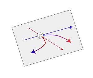
Figure 9. Schematics of DS-VT $_{r-t}$: (a) sketch of the local LEV structure; and (b)
  $180^{\circ }$ reversal of the local radial vorticity component via DS-VT
 $_{r-t}$. The white box represents a specific grid point, and blue and red lines indicate negative radial and positive tangential directions, respectively.
Thus the dual stages of DS-VT $_{r-t}$ tend to reverse the local radial vorticity inside the LEV and can remove, at least partly, the newly generated radial vorticity (due to the shear at the leading edge). More importantly, the DS-VT
 $_{r-t}$ can also be interpreted as a negative feedback loop for the radial vorticity component, with the feedback paths as
  $T_{r\rightarrow t}^{(+)}$ and
  $T_{t\rightarrow r}^{(+)}$. This feedback process starts with an increase of negative radial vorticity component inside the LEV, and then enhances the positive tangential vorticity component via
  $T_{r\rightarrow t}^{(+)}$. Subsequently, the enhanced positive tangential vorticity component is further reoriented into a positive radial vorticity component via
  $T_{t\rightarrow r}^{(+)}$, and thus alleviates the growth of the negative radial vorticity component. Note that although we are currently unable to to prove the stability of this negative feedback loop in a control-theoretic framework, the DS-VT
 $_{r-t}$ separates itself from other proposed mechanisms in that its negative feedback nature is a necessary condition for stability in dynamical systems. Moreover, PVT
 $_t$ and
  $S_t$ are also involved to sustain the growth of the tangential vorticity component, and the radial vorticity component is also regulated by
  $C_{rr}$ and PVT
 $_r$ (Chen et al. Reference Chen, Wang, Zhou, Wu and Cheng2022).
In addition, the role of radial and tangential Coriolis accelerations in the LEV stability can now be shown further based on our previous study (Chen et al. Reference Chen, Wang, Zhou, Wu and Cheng2022) and current analysis. An appropriate vertical gradient of tangential Coriolis acceleration can lead to a tilting of planetary vorticity into the radial direction opposite to the leading-edge vorticity and thus directly reduces the radial vorticity, i.e. PVT $_r$, which is almost
  $\textit {Re}$-independent (Chen et al. Reference Chen, Wang, Zhou, Wu and Cheng2022). Our current analysis further shows that the vertical gradient of radial Coriolis acceleration can reorient the planetary vorticity into enhancing the tangential vorticity component in the LEV. This enhancement can further increase the vortex tilting of the tangential vorticity component into the radial direction opposite to the radial vorticity in the LEV (
 $T_{t\rightarrow r}^{(+)}$ in figure 8), thus limiting the growth of the LEV. Unlike previous numerical manipulations of the Navier–Stokes equations (Jardin & David Reference Jardin and David2015), our analysis provides an explicit understanding of the Coriolis acceleration in LEV stability in terms of its direct relationship with vorticity transport (3.1).
3.3. $\textit {Re}$ effects

The  $\textit {Re}$ effects on the achievement of a constant
  $\hat {\omega }_t^*/{\varGamma }$ and DS-VT
 $_{r-t}$ are examined here. As shown in figure 10(a), the LEV at
  $\textit {Re}=100$ remains stable until the wingtip, while the evolution of LEV at
  $\textit {Re}=5000$ is almost identical to that at
  $\textit {Re}=500$ and 1500. Given a
  $\textit {Re}$ value higher than 500, the stable LEV region is retained within the mid-span, and the constant
  $\hat {\omega }_t^*/{\varGamma }$ region is enlarged in both the vertical and tangential directions (figures 10c,e). However, the constant
  $\hat {\omega }_t^*/\varGamma$ at
  $\textit {Re}> 500$ almost follows an identical trend over the span (figures 10b,d), suggesting that a further increase of
  $\textit {Re}$ above 500 leads to negligible variations in the overall LEV intensity. Therefore, the
  $\hat {\omega }_t^*/{\varGamma }$ within the stable LEV region is almost a constant at
  $\textit {Re}>500$, and the spanwise limit of the stable LEV is also retained (figure 10f). In contrast, the intensities of the radial and tangential vorticity components at
  $\textit {Re}=100$ are both lower than those at a higher
  $\textit {Re}$, and less unsteady behaviour results in the outboard region. It is remarkable that the constant
  $\hat {\omega }_t^*/\varGamma$ at
  $\textit {Re}=100$ is also close to that at
  $\textit {Re}> 500$, and this constant
  $\hat {\omega }_t^*/\varGamma$ is maintained beyond the mid-span (towards
  $|r|=3$) at
  $\textit {Re}=100$, corresponding to a spanwise expansion of the stable LEV region at
  $\textit {Re}<500$.

Figure 10. Effects of  $\textit {Re}$ on the LEV structure and its vorticity components: (a) 3-D vortical structures at
  $\textit {Re}=100$, (b) LEV circulation, (c) 3-D vortical structures at
  $\textit {Re}=500$, (d) local tangential vorticity intensity, (e) 3-D vortical structures at
  $\textit {Re}=5000$ and (f) intensity ratio. The 3-D vortical structures are outlined by
  ${Q}=1$. The curves in (b,d,f) are at
  $\lambda =4$.
The critical vorticity transport terms that participate in the DS-VT $_{r-t}$ and regulate the tangential vorticity component at different
  $\textit {Re}$ values are shown in figure 11. The volumetric averages of these terms are calculated within the stable LEV regions (figure 11a), i.e.
  $|r|=r_0\approx 2.4$ at
  $\textit {Re} > 500$, and
  $|r|=r_0\approx 3$ at
  $\textit {Re}=100$. To eliminate the difference in LEV strength, the vorticity transport terms are scaled by the local LEV circulation and tangential vorticity intensity ahead of calculating their volumetric averages. It is shown that all critical vorticity transport terms are enhanced as
  $\textit {Re}$ increases from 100 to 1000, except for
  $\widetilde {\mathrm {PVT}}_{t}^+$, the intensity of which is almost
  $\textit {Re}$-independent. A further increase of
  $\textit {Re}$ above 1000 can result in only minor enhancements. This indicates that the DS-VT
 $_{r-t}$, which is driven by vortex tilting, is highly
  $\textit {Re}$-dependent at
  $\textit {Re}< 1000$. At
  $\textit {Re}>1000$,
  $\tilde {T}_{r\rightarrow t}^+$ becomes comparable to
  $\widetilde {\mathrm {PVT}}_{t}^+$, and both contribute to the increase of the tangential vorticity component (figure 11). Note that the vortex stretching (
 $\tilde {S}_t^+$) can also intensify the tangential vorticity component. In contrast,
  $\tilde {T}_{r\rightarrow t}^+$ is almost negligible at
  $\textit {Re}<500$ (figure 11), and the contribution of vortex tilting in increasing the tangential vorticity component is dominated by
  $\widetilde {\mathrm {PVT}}_{t}^+$. Therefore, despite the fact that the constant
  $\hat {\omega }_t^*/\varGamma$ can be achieved at
  $\textit {Re}< 500$, the underlying mechanisms in the evolution of the tangential vorticity component may be distinct. At these
  $\textit {Re}$ values, the DS-VT
 $_{r-t}$ is almost absent due to a negligible
  $\tilde {T}_{r\rightarrow t}^+$, and, as alternatives,
  $\widehat {\mathrm {PVT}}_{t}^+$ and
  $\hat {S}_t^+$ contribute to the increment of the tangential vorticity component.

Figure 11. Comparison of critical vorticity transport terms related to DS-VT $_{r-t}$ at the steady states (
 $\lambda =4$) of different
  $\textit {Re}$ values.
3.4. AR and Ro effects
The impacts of AR and Ro are investigated separately under two procedures (figure 1b). This is because a conventional enlargement of AR can result in a concomitant increase of Ro, thus leading to coupled effects of AR and Ro. In our research, the first procedure moves the wing (with a fixed AR) centrifugally at  $\textit {Re}=1500$, therefore the spanwise gradient of the incoming velocity, as well as rotational accelerations, is reduced, indicating a reduction of rotational effects. The second procedure varies the tip and root effects while preserving the local incoming velocity (and its gradient) at a certain revolving radius. Therefore, the complex effects of AR and Ro can be separated mostly into the rotational effects and wingtip/root interactions.
3.4.1. Ro effects under a constant AR
The rotational effects on the constant  $\hat {\omega }_t^*/\varGamma$, the critical vorticity transport of DS-VT
 $_{r-t}$ and other relevant tangential vorticity transport components are examined here. As shown in figure 4 (
 $\textit {Ro}=2.56$ and
  $r_0=0.9$) and figure 12, the unsteady LEV region can be enlarged significantly when the wing is shifted centrifugally, i.e. an increase of
  $r_0$ and Ro. Moreover, the unsteady LEV behaviour at a larger Ro can be featured as the shedding of a horseshoe-like vortical structure (figure 12c), which resembles the LEV shedding in two-dimensional translating wings (Visbal & Garmann Reference Visbal and Garmann2019). Since the constant
  $\hat {\omega }_t^*/\varGamma$ is located within the stable LEV region, an increase of Ro can compress the steady-state
  $\hat {\omega }_t^*/\varGamma$ towards the wing root (figure 12c). Note that a constant
  $\hat {\omega }_t^*/\varGamma$ can still be observed during the LEV formation period at a high Ro value (figures 12b,c) when the LEV is stable along the span and less unsteady behaviour is developed.

Figure 12. Effects of Ro on the 3-D vortical structures of revolving wings: (a)  $\textit {Ro}=1.73$ and
  $r_0=0$, (b)
  $\textit {Ro}=4$ and
  $r_0=2.41$ and (c)
  $\textit {Ro}=6$ and
  $r_0=4.44$. The 3-D vortical structures are outlined by
  ${Q}=1$.
A sectional analysis at  $\textit {Ro}=1.73$, 2.56, 4 and 6 shows that as Ro increases, the radial vorticity intensity at
  $R_g$ is almost unchanged since the local incoming velocity is retained (figures 13a,b). Here, the
  $x$-axes of figure 13 are normalized by the span, and the root cutout is excluded, thus not representing the local revolving radius. Moreover, an increase of Ro can enlarge the local incoming velocity within
  $R_g$ while reducing the local incoming velocity beyond
  $R_g$, leading to a weaker spanwise gradient of incoming velocity. Therefore, as Ro increases, the LEV circulation within
  $R_g$ is increased, while that beyond
  $R_g$ is attenuated. The increase of Ro can also moderate the linear spanwise increment of the tangential vorticity component during the LEV formation period, and results in an almost levelled profile at
  $\textit {Ro}=4$ and 6 (figure 13c). This levelled distribution can be compressed further towards the root at the steady state, and strong unsteady variations are observed in the outboard region (figure 13d). Therefore, the constant
  $\hat {\omega }_t^*/{\varGamma }$ is quickly established for the revolving wing at
  $\textit {Ro}=1.73$, and can cover most of the span until
  $R_g$ (figure 13e). As Ro increases, the steady-state
  $\hat {\omega }_t^*/{\varGamma }$ is remarkably compressed towards the root, and almost no steady-state
  $\hat {\omega }_t^*/{\varGamma }$ is observed at
  $\textit {Ro}=6$ (figures 13f–h). Together with the 3-D structures in figure 12, it is shown that the constant
  $\hat {\omega }_t^*/{\varGamma }$ and the stable LEV region are still mostly overlapped as Ro varies.

Figure 13. Effects of Ro on the vorticity component distribution within the LEV: (a,b) LEV circulation at  $\lambda =2$ and 4; (c,d) intensity of tangential vorticity component at
  $\lambda =2$ and 4; (e–h) intensity ratio at
  $\textit {Ro}=1.73$, 2.56, 4 and 6, respectively. The LEV circulation and local intensity of the tangential vorticity component at
  $\lambda =6$ are also plotted, by dashed lines, in (b,d).
Moreover, the local revolving radius corresponding to the spanwise limits of the constant  $\hat {\omega }_t^*/{\varGamma }$ (
 $r_{{lim}}$) at a higher Ro can still maintain a
  $r_{\mathrm {lim}}$ close to 3 (see table 2). This further indicates that the formation of a constant
  $\hat {\omega }_t^*/{\varGamma }$ is strongly dependent on rotational accelerations, which are argued to be strong within a revolving radius of 3 (Lentink & Dickinson Reference Lentink and Dickinson2009; Jardin & Colonius Reference Jardin and Colonius2018). Note that the revolving radius of the wing root exceeds 3 at
  $\textit {Ro}=5- 7$, thus almost no constant
  $\hat {\omega }_t^*/{\varGamma }$ occurs (figure 13h). In addition,
  $r_{{lim}}$ at
  $\textit {Ro}=1.73$ and 2.1 can be slightly lower than 3. This may be attributed to the interaction of the tip vortex, which can break down the stable flow pattern within a certain chord length from the wingtip. Therefore, despite the fact that, ideally,
  $r_{{lim}}$ at these Ro values can be up to 3, the constant
  $\hat {\omega }_t^*/{\varGamma }$ still cannot cover the wingtip region.
Table 2. Spanwise limits ( $r_{{lim}}$) of the constant
  $\hat {\omega }_t^*/{\varGamma }$ at various Ro values.

The critical vorticity transport terms that are relevant to DS-VT $_{r-t}$ are also examined at representative Ro values (figure 14). Since an increase of Ro can moderate rotational accelerations,
  $\widehat {\mathrm {PVT}}_t^+$ within the LEV is significantly reduced as Ro increases to 6, and the linear increase over the span is levelled off, indicating attenuated Coriolis effects (figures 14c,d). Moreover, a strong vortex tilting of the radial vorticity component into the positive tangential direction (
 $\hat {T}_{r\rightarrow t}^+$) is generated around
  $R_g$ at
  $\textit {Ro}=1.73$, whereas no steady-state
  $\hat {T}_{r\rightarrow t}^+$ is observed along the entire span at
  $\textit {Ro}=6$ (figures 14a,b). A similar pattern is also observed in the vortex tilting of the tangential vorticity component into the positive radial direction (
 $\hat {T}_{t\rightarrow r}^+$), except for the difference in magnitudes (figures 14g,h). The transient
  $\hat {T}_{t\rightarrow r}^+$ peaks at
  $\textit {Ro}=6$ and
  $\lambda =3- 5$ are located within the detached (or being detached) LEV (figure 14h), and this is not regarded as a contributor to LEV stability since it is attributed to the complex unsteady flow in the detached (or being detached) LEV. Considering the enhancement of
  $\hat {T}_{r\rightarrow t}^+$ and
  $\hat {T}_{t\rightarrow r}^+$ at a lower Ro value, it is inferred that the establishment of DS-VT
 $_{r-t}$ is underpinned by strong rotational accelerations, and increasing Ro can moderate the contribution of DS-VT
 $_{r-t}$ in regulating the LEV circulation. In addition, the vortex stretching (
 $\hat {S}_t^+$) can be a stable contributor to the increment of the tangential vorticity component at a low Ro value (figure 14e), whereas its effects are significantly reduced as Ro increases (figure 14f). As for
  $\hat {T}_{t\rightarrow r}^+$, the transient peaks of
  $\hat {S}_t^+$ at
  $\lambda =2- 5$ also result from the complex unsteady flows. As discussed above, it can be concluded that the breakdown of constant
  $\hat {\omega }_t^*/{\varGamma }$ at a higher Ro value is attributed to the remarkable reduction of all these vortex tilting and stretching terms, which is further led by a weaker rotational nature.

Figure 14. Effects of Ro on the critical vortex tilting and stretching terms in the tangential and radial directions: (a,b)  $\hat {T}_{r\rightarrow t}^+$ at
  $\textit {Ro}=1.73$ and 6; (c,d)
  $\widehat {\mathrm {PVT}}_t^+$ at
  $\textit {Ro}=1.73$ and 6; (e,f)
  $\hat {S}_t^+$ at
  $\textit {Ro}=1.73$ and 6; (g,h)
  $\hat {T}_{t\rightarrow r}^+$ at
  $\textit {Ro}=1.73$ and 6. The transient cylindrical slices at 30 % span are given in (f,h).
3.4.2. AR effects under a constant Ro
The effects of tip vortex and root vortex on the constant  $\hat {\omega }_t^*/{\varGamma }$ and critical vorticity transport terms are elucidated through a variation of AR at
  $\textit {Ro}=2.56$. Compared to the benchmark case (figure 4), the constant
  $\hat {\omega }_t^*/{\varGamma }$, as well as the stable LEV region, can be extended beyond
  $R_g$ when AR increases to 4.44 (figures 15b,d), indicating that the spanwise limit of the stable LEV at
  $\textit {AR}=3$ may be affected by the interaction of the tip vortex. Alternatively, a reduction of AR can still retain a stable LEV within most of the span, whereas the constant
  $\hat {\omega }_t^*/{\varGamma }$ is significantly attenuated due to the interaction of a stronger root vortex (figures 15a,c). Note that the
  $x$-axis denotes the relative position with respect to the span in these plots, instead of the local revolving radius. It is shown that the constant
  $\hat {\omega }_t^*/{\varGamma }$ covers almost 60 % span at
  $\textit {AR}=4.44$, while occurring only around the mid-span at
  $\textit {AR}=1$. Therefore, it is indicated that although a stable LEV may be retained at
  $\textit {AR}=1$, an interaction with strong tip and root vortices can break down the constant
  $\hat {\omega }_t^*/{\varGamma }$.

Figure 15. Effects of AR on the LEV structure and its vorticity components at  $\textit {Ro}=2.56$: (a,b) 3-D vortical structures at
  $\textit {AR}=1$ (
 $r_0=2.05$) and
  $\textit {AR}=4.44$ (
 $r_0=0$); and (c,d) the intensity ratios at
  $\textit {AR}=1$ (
 $r_0=2.05$) and
  $\textit {AR}=4.44$ (
 $r_0=0$). The 3-D vortical structures are outlined by
  ${Q}=1$.
A further examination of the critical vortex tilting and stretching terms at  $\textit {AR}=3$ and 4.44 shows that due to a reduction of AR, the enhancement of the root vortex leads to a local increase of
  $\hat {T}_{r\rightarrow t}^+$,
  $\hat {S}_t^+$ and
  $\hat {T}_{t\rightarrow r}^+$ within the 25 % span (figures 16a,e,g), which is beneficial to limit the local radial vorticity component, and contributes to LEV stability. On the contrary, an obvious peak of
  $\hat {T}_{r\rightarrow t}^+$ is generated around
  $R_g$ at
  $\textit {AR}=4.44$ due to reduced root vortex effects (figure 16b). This
  $\hat {T}_{r\rightarrow t}^+$ peak can contribute to the enlargement of the DS-VT
 $_{r-t}$ and the constant
  $\hat {\omega }_t^*/{\varGamma }$ towards the wingtip. The enhancement of the root vortex, despite the increment in the wing root
  $\hat {T}_{r\rightarrow t}^+$, reduces the
  $\hat {T}_{r\rightarrow t}^+$ peak around
  $R_g$ (figure 16a). In addition, the variation of AR under a constant Ro results in trivial variations of
  $\widehat {\mathrm {PVT}}_t^+$ (figures 16c,d). According to figure 16, the role of the root vortex in stabilizing the local LEV can be concluded as a local enhancement of vortex tilting and stretching, and therefore intensifies the local DS-VT
 $_{r-t}$. However, this enhancement fails to maintain a constant
  $\hat {\omega }_t^*/{\varGamma }$ due to the significant changes of other vorticity transport terms around the wing root (e.g.
  $\hat {S}_t^+$).

Figure 16. Effects of AR on the critical vortex tilting and stretching terms at  $\textit {Ro}=2.56$: (a,b)
  $\hat {T}_{r\rightarrow t}^+$ at
  $\textit {AR}=3$ and 4.44; (c,d)
  $\widehat {\mathrm {PVT}}_t^+$ at
  $\textit {AR}=3$ and 4.44; (e,f)
  $\hat {S}_t^+$ at
  $\textit {AR}=3$ and 4.44; (g,h)
  $\hat {T}_{t\rightarrow r}^+$ at
  $\textit {AR}=3$ and 4.44.
4. Conclusions
The vorticity features of a stable leading-edge vortex (LEV) and a novel mechanism, i.e. a dual-stage vortex tilting of radial and tangential vorticity components (DS-VT $_{r-t}$), that contributes to LEV stability are investigated systematically in this study, including the effects of Reynolds number (Re), aspect ratio (AR) and Rossby number (Ro). The revolving wing is modelled as a rectangular plate with a fixed angle of attack (45
 $^{\circ }$) and undergoes a constant angular acceleration within the first 0.5 chord length of travel at the radius of gyration, followed by a constant speed revolving. The unsteady flow around the wing is simulated via an in-house solver, and an analysis of vorticity transport is conducted in the co-rotating frame. Our results show that a constant ratio of tangential and radial vorticity components exists in the stable LEV region, and the DS-VT
 $_{r-t}$ mechanism can reduce the radial vorticity in the LEV and contribute to LEV stability. This vortex-tilting-based mechanism acts as a negative feedback loop that reverses the direction of radial vorticity component in the LEV, thereby contributing to its stability. The achievement of DS-VT
 $_{r-t}$ depends on properly established velocity gradients in both the radial and tangential directions. Moreover, the vertical gradient of radial Coriolis acceleration can enhance the tangential vorticity component and thus enhances the second stage of this negative feedback loop to reduce the radial vorticity component. Further analysis suggests that DS-VT
 $_{r-t}$ is significant when
  $\textit {Re}>1000$, and becomes negligible at
  $\textit {Re}<500$. This is because the conversion of the radial vorticity component into the tangential vorticity component becomes negligible at
  $\textit {Re}<500$, and the tangential vorticity component is mostly enhanced by the radial Coriolis acceleration. In addition, an increase of Ro, i.e. a centrifugal movement of the wing, can shrink the DS-VT
 $_{r-t}$ and the stable LEV region towards the wing root, while the spanwise limit of the region with a constant vorticity ratio is maintained around 3 chord lengths with respect to the centre of rotation. The existence of a strong root vortex can enhance the local vortex tilting and stretching, which is beneficial to the local DS-VT
 $_{r-t}$ and LEV stability, while almost no constant vorticity ratio is achieved due to the concomitant change of other vorticity transport terms. Within our parameters investigated in this study, the ratio of tangential and radial vorticity components within the stable LEV region remains within the range of 0.3 and 0.6 in magnitude (except for the wing at
  $\textit {AR}=1$ and
  $\textit {Ro}=2.56$, with strong influences of root vortex and tip vortex), which suggests a correlation between LEV stability and the vorticity direction. These findings can provide insights regarding the DS-VT
 $_{r-t}$ and its dependence on
  $\textit {Re}$, AR and Ro, which strengthens our understanding of LEV stability on both bio-inspired flapping wings and autorotating seeds.
Funding
This research was financially supported by the National Natural Science Foundation of China (grant nos 12002082, 11902017, 12072013) and the Chinese Postdoctoral Science Foundation (National Postdoctoral Programme for Innovative Talents, grant no. BX20220368).
Declaration of interests
The authors report no conflict of interest.
Author contributions
L.C and C.Z. contributed equally to this work.


