


1. Introduction
This article presents a general description of vorticity generation on interfaces and boundaries in three-dimensional flows, which is a direct extension of our previous two-dimensional description of vorticity generation (Terrington, Hourigan & Thompson Reference Terrington, Hourigan and Thompson2020). This formulation considers a generalised interface, which may represent a wide range of boundaries, including no-slip and free-slip walls, free surfaces and fluid–fluid interfaces. This formulation effectively extends Morton's (Reference Morton1984) inviscid model of vorticity creation to general interfaces in three dimensions. Under this interpretation, vorticity creation is an inviscid process, due to the relative acceleration between fluid elements on each side of the interface, caused by tangential pressure gradients or body forces. Moreover, the current formulation is expressed as a conservation law for vorticity, and, given appropriate boundary conditions, the total circulation in many flow configurations remains constant throughout flow evolution.
Our prior two-dimensional description of interfacial vorticity dynamics (Terrington et al. Reference Terrington, Hourigan and Thompson2020) is expressed as a conservation law for the circulation in a two-dimensional region. We considered the system of control areas in figure 1, where  $I$ is the interface between two fluids,
  $A_1$ and
  $A_2$ are the portions of a control area,
  $A$, on each side of the interface, and
  $C$ is the outer boundary curve. The total circulation in this system includes vorticity in both fluids, as well as circulation contained in an interface vortex sheet representing the slip velocity on the interface:
 \begin{equation} \varGamma = \oint_{C} \boldsymbol{u} \boldsymbol{\cdot} \mathrm{d} \boldsymbol{s} = \int_{A_1} \omega \,\mathrm{d} A + \int_{A_2} \omega \,\mathrm{d} A + \int_I \gamma \,\mathrm{d} s, \end{equation}
where  $\gamma = \boldsymbol {\hat {t}} \boldsymbol {\cdot } (\boldsymbol {u}_2 - \boldsymbol {u}_1$) is the density of circulation contained in the interface vortex sheet.

Figure 1. The control area for Terrington et al.'s (Reference Terrington, Hourigan and Thompson2020) two-dimensional circulation balance (1.2). Here  $I$ is the interface between two fluids;
  $A_1$ and
  $A_2$ are the portions of a control area,
  $A$, in each fluid;
  $C$ is the outer boundary of
  $A$;
$A$;  $\boldsymbol {\hat {\bar n}}$ is the outwards-facing unit normal to
  $C$; and
  $\boldsymbol {\hat {n}}$ and
  $\boldsymbol {\hat {t}}$ are the unit normal and tangent vectors to
  $I$, respectively.
In Terrington et al. (Reference Terrington, Hourigan and Thompson2020), we give the following expression for the rate of change of total circulation:
 \begin{align} \frac{\mathrm{d} \varGamma}{\mathrm{d} t} & = \oint_C \nu \boldsymbol{\hat{\bar n}} \boldsymbol{\cdot} \boldsymbol{\nabla} \omega \,\mathrm{d} s + \oint_C \boldsymbol{\hat{\bar{n}}} \boldsymbol{\cdot} (\boldsymbol{v}^{b} - \boldsymbol{u})\omega \,\mathrm{d} s - [[ \frac{p}{\rho} ]]_b + [[ \frac{p}{\rho} ]]_a - [\kern-1pt[ \varPhi_g ]\kern-1pt]_b + [\kern-1pt[ \varPhi_g]\kern-1pt]_a \nonumber\\ &\quad + \left.\gamma (\boldsymbol{v}^b \boldsymbol{\cdot} \boldsymbol{\hat{t}})\right|_b - \left.\gamma (\boldsymbol{v}^b \boldsymbol{\cdot} \boldsymbol{\hat{t}})\right|_a + \frac{1}{2} [\kern-1pt[(\boldsymbol{u} \boldsymbol{\cdot} \boldsymbol{\hat{t}})^2 ]\kern-1pt]_a - \frac{1}{2} [\kern-1pt[(\boldsymbol{u} \boldsymbol{\cdot} \boldsymbol{\hat{t}})^2 ]\kern-1pt]_b, \end{align}
where double square brackets denote the jump in some quantity across the interface. The first two terms in this equation represent the transport of vorticity across the control area boundary, by both advection ( $\boldsymbol {\hat {\bar {n}}} \boldsymbol {\cdot } (\boldsymbol {v}^{b}-\boldsymbol {u})\omega$) and viscous diffusion (
 $\nu \boldsymbol {\hat {\bar {n}}} \boldsymbol {\cdot } \boldsymbol {\nabla } \omega$) in the fluid interior, while the terms involving
  $\boldsymbol {v}^b \boldsymbol {\cdot } \boldsymbol {\hat {t}}$ and
  $\boldsymbol {u} \boldsymbol {\cdot } \boldsymbol {\hat {t}}$ describe transport of circulation along the interface. The remaining terms describe the creation of vorticity on the interface, by either tangential pressure gradients (
 $p/\rho$) or body forces (
 $\varPhi _g$). Importantly, (1.2) does not depend on the boundary conditions at the interface, and can be applied to a wide range of boundaries, including solid walls, free surfaces and no-slip or free-slip fluid–fluid interfaces.
Equation (1.2) provides a general description of vorticity generation, which extends Morton's (Reference Morton1984) inviscid model of vorticity creation to general two-dimensional interfaces (Terrington et al. Reference Terrington, Hourigan and Thompson2020). Morton attributes the creation of vorticity on a solid boundary to the inviscid relative acceleration between the fluid and the solid, driven by either tangential pressure gradients or tangential acceleration of the solid boundary. Similarly, in (1.2), circulation is generated by the inviscid relative acceleration between fluid elements on each side of the interface, due to either tangential pressure gradients or body forces. Under this interpretation, viscosity is not responsible for the creation of vorticity; however, viscosity is responsible for the diffusion of vorticity into the fluid interior, after it has been generated by the inviscid mechanism.
Equation (1.2) also describes a general principle of vorticity conservation for interfacial and free-surface flows. In many flow configurations, the right-hand side of (1.2) is zero, and the total circulation remains constant throughout time (Brøns et al. Reference Brøns, Thompson, Leweke and Hourigan2014, Reference Brøns, Thompson, Leweke and Hourigan2020; Terrington et al. Reference Terrington, Hourigan and Thompson2020). A similar principle of vorticity conservation for free-surface flows was presented by Lundgren & Koumoutsakos (Reference Lundgren and Koumoutsakos1999), which is generalised to two-dimensional interfaces by Brøns et al. (Reference Brøns, Thompson, Leweke and Hourigan2014, Reference Brøns, Thompson, Leweke and Hourigan2020) and Terrington et al. (Reference Terrington, Hourigan and Thompson2020).
In this article, we extend (1.2) to three-dimensional flows, providing a general description of vorticity generation and conservation on interfaces and boundaries in three-dimensional flows. This formulation extends the main features of our two-dimensional description – the inviscid theory of vorticity creation, and the conservation of vorticity – to three-dimensional flows. Moreover, there are several new features that must be considered in three dimensions, including the effects of vortex stretching and tilting, and the appearance of surface-normal vorticity in the interface, that do not occur in two dimensions.
In this article, the effects of vortex stretching and tilting are represented as boundary fluxes, so that the current formulation retains the form of an integral conservation law. Moreover, we provide a physical interpretation of the vortex stretching/tilting boundary flux: the vortex stretching/tilting flux represents the advection of surface-normal vorticity in the boundary surface of a control volume, which gives a direct measure of the net generation of vorticity by vortex stretching and tilting in the fluid interior. If vortex filaments do not intersect the control-volume boundary, then the total rate of change of vorticity due to vortex stretching and tilting is zero, and the total circulation is conserved.
The second aspect that must be considered in three dimensions is the behaviour of surface-normal vorticity at the interface. In this article, we provide a transport equation for the surface-normal vorticity in the interface or free surface, which relates the appearance of surface-normal vorticity in the surface to the viscous diffusion of surface-tangential vorticity across the boundary. In particular, this leads to a new interpretation of vortex connection to a free surface, where vortex filaments are broken near the free surface, and the ends of these filaments attach to the free surface (Bernal & Kwon Reference Bernal and Kwon1989; Lugt & Ohring Reference Lugt and Ohring1994; Gharib & Weigand Reference Gharib and Weigand1996; Ohring & Lugt Reference Ohring and Lugt1996; Zhang, Shen & Yue Reference Zhang, Shen and Yue1999). Under the interpretation proposed in this paper, the appearance of surface-normal vorticity in the free surface is directly attributed to the viscous flux of surface-tangential vorticity out of the fluid. Therefore, the breaking open of vortex filaments, and subsequent attachment to the free surface, are attributed to a single physical process, which reflects the kinematic condition that vortex lines do not end in the fluid interior.
The structure of this article is as follows. In § 2, we derive the vorticity balance for a general interface in a three-dimensional flow. Next, in § 3, we present an interpretation of the vortex stretching/tilting boundary flux. Then, in § 4, we consider the specific boundary conditions for no-slip fluid–fluid interfaces, free surfaces and solid walls. Finally, in § 5, we consider the generation of vorticity in compressible flows.
2. A three-dimensional theory of vorticity creation
In this section, we outline a three-dimensional formulation of interfacial vorticity dynamics, for incompressible Newtonian fluids, which generalises several previous results. First, the total vorticity is shown to be conserved in three-dimensional flows, generalising our two-dimensional description (Brøns et al. Reference Brøns, Thompson, Leweke and Hourigan2014, Reference Brøns, Thompson, Leweke and Hourigan2020; Terrington et al. Reference Terrington, Hourigan and Thompson2020). Second, Morton's (Reference Morton1984) inviscid theory of vorticity creation is shown to hold for generalised interfaces in three dimensions. The only mechanism by which vorticity is created on an interface is the inviscid relative acceleration between fluid elements on each side of the interface, due to either tangential pressure gradients or body forces. The general formulation is independent of the tangential boundary conditions, and is therefore applicable to a wide range of interfaces and boundaries, including no-slip fluid–fluid interfaces, solid boundaries and free surfaces.
2.1. Preliminary theory
The dynamics of vorticity can be understood by considering the Helmholtz equation – a transport equation for vorticity obtained from the Navier–Stokes equations. For an incompressible Newtonian fluid of constant viscosity, this equation is expressed as
 \begin{equation} \frac{\partial \boldsymbol{\omega}}{\partial t} + \boldsymbol{u} \boldsymbol{\cdot} \boldsymbol{\nabla} \boldsymbol{\omega} = \boldsymbol{\omega} \boldsymbol{\cdot} \boldsymbol{\nabla} \boldsymbol{u} + \nu \nabla^2 \boldsymbol{\omega}.\end{equation}
The left-hand side of (2.1) is the material derivative of vorticity, while the first term on the right-hand side represents the effects of vortex stretching and tilting. The final term on the right-hand side describes the viscous diffusion of vorticity.
In this article, we develop a conservation law for the volume integral of vorticity,
 \begin{equation} \boldsymbol{\varGamma} = \int_V \boldsymbol{\omega} \,\mathrm{d} V = \oint_{\partial V} \boldsymbol{\hat{n}} \times \boldsymbol{u} \,\mathrm{d} S, \end{equation}
where  $\boldsymbol {\hat {n}}$ is the outward-directed unit normal to the control-volume boundary. Equation (2.2) relates the total vorticity in
  $V$ to the velocity on the control-volume boundary, reminiscent of the relationship between circulation and vorticity in a two-dimensional flow. For this reason, we refer to
  $\boldsymbol {\varGamma }$ as the ‘vector circulation’.
An integral conservation law for vorticity in a single fluid domain is constructed by first using the Reynolds transport theorem:
 \begin{equation} \frac{\mathrm{d} \boldsymbol{\varGamma}}{\mathrm{d} t} = \frac{\mathrm{d} }{\mathrm{d} t}\int_V \boldsymbol{\omega} \,\mathrm{d} V = \int_V \frac{\partial \boldsymbol{\omega}}{\partial t} \mathrm{d} V + \oint_{\partial V} (\boldsymbol{v}^{b}\boldsymbol{\cdot} \boldsymbol{\hat{n}} )\boldsymbol{\omega} \,\mathrm{d} S, \end{equation}
where  $\boldsymbol {v}^{b}$ is the velocity of the control-volume boundary. Then, (2.1) is substituted into this relationship, providing the following expression:
 \begin{equation} \frac{\mathrm{d} \boldsymbol{\varGamma}}{\mathrm{d} t} = \oint_{\partial V} \boldsymbol{\omega} (\boldsymbol{v}^{b} -\boldsymbol{u}) \boldsymbol{\cdot} \boldsymbol{\hat{n}} \,\mathrm{d} S + \oint_{\partial V} (\boldsymbol{\omega} \boldsymbol{\cdot} \boldsymbol{\hat{n}}) \boldsymbol{u} \,\mathrm{d} S - \oint_{\partial V} \boldsymbol{\sigma}\, \mathrm{d} S. \end{equation}
The terms on the right-hand side of (2.4) describe (from left to right) the effects of advection, vortex stretching/tilting and viscous diffusion, as fluxes of vorticity across the control-volume boundary, which contribute to the net rate of change of vorticity in  $V$.
$V$.
Of particular interest is the viscous term ( $\boldsymbol {\sigma }$), often referred to as the ‘boundary vorticity flux’. This term describes the rate at which vorticity diffuses across
  $\partial V$, under the action of viscous forces, and is generally understood to indicate the rate of vorticity creation on solid boundaries (Lighthill Reference Lighthill1963; Panton Reference Panton1984; Wu & Wu Reference Wu and Wu1993; Terrington, Hourigan & Thompson Reference Terrington, Hourigan and Thompson2021), free surfaces (Rood Reference Rood1994b; Lundgren & Koumoutsakos Reference Lundgren and Koumoutsakos1999; Peck & Sigurdson Reference Peck and Sigurdson1999) and fluid–fluid interfaces (Wu Reference Wu1995; Brøns et al. Reference Brøns, Thompson, Leweke and Hourigan2014; Terrington et al. Reference Terrington, Hourigan and Thompson2020).
The boundary vorticity flux was first defined by Lighthill (Reference Lighthill1963), and this definition was generalised to curved boundaries by Panton (Reference Panton1984):
 \begin{equation} \boldsymbol{\sigma'} ={-}\nu\boldsymbol{\hat{n}} \boldsymbol{\cdot} \boldsymbol{\nabla} \boldsymbol{\omega}. \end{equation}
The Lighthill–Panton definition is justified by integration of the viscous diffusion term across  $V$,
$V$,
 \begin{equation} \int_V \nu \nabla^2 \boldsymbol{\omega}\,\mathrm{d} V = \oint_{\partial V} \nu \boldsymbol{\hat{n}} \boldsymbol{\cdot} \boldsymbol{\nabla} \boldsymbol{\omega} \,\mathrm{d} S. \end{equation}
However, this definition is not unique, and an alternative representation of the viscous term,
 \begin{equation} \int_V -\nu \boldsymbol{\nabla} \times (\boldsymbol{\nabla} \times \boldsymbol{\omega} )\,\mathrm{d} V ={-}\oint_{\partial V} \nu \boldsymbol{\hat{n}} \times (\boldsymbol{\nabla} \times \boldsymbol{\omega}) \,\mathrm{d} S,\end{equation}
led Lyman (Reference Lyman1990) to propose an alternative definition of the boundary vorticity flux as
 \begin{equation} \boldsymbol{\sigma} =\nu \boldsymbol{\hat{n}} \times(\boldsymbol{\nabla} \times \boldsymbol{\omega}). \end{equation}
There is no obvious physical argument to prefer either Lighthill's or Lyman's definition (Terrington et al. Reference Terrington, Hourigan and Thompson2021), and we are free to take either definition. Lyman's definition is used in this article, as it offers several compelling advantages over the Lighthill–Panton definition (Terrington et al. Reference Terrington, Hourigan and Thompson2021). This approach differs from previous formulations of interfacial and free-surface vorticity dynamics, which have used the Lighthill–Panton definition (Lugt & Ohring Reference Lugt and Ohring1992; Rood Reference Rood1994a,Reference Roodb; Wu Reference Wu1995; Sarpkaya Reference Sarpkaya1996; Peck & Sigurdson Reference Peck and Sigurdson1998, Reference Peck and Sigurdson1999; Lundgren & Koumoutsakos Reference Lundgren and Koumoutsakos1999).
The first benefit of Lyman's definition is that it allows Morton's (Reference Morton1984) inviscid description of vorticity generation to be directly applied to three-dimensional flows (Lyman Reference Lyman1990; Terrington et al. Reference Terrington, Hourigan and Thompson2021). Under the Lighthill–Panton definition, an additional viscous contribution to the creation of vorticity must be included, which is difficult to accommodate under Morton's interpretation.
Lyman's definition also more clearly explains the mechanism that enforces the kinematic condition that vortex lines do not end inside the fluid (Terrington et al. Reference Terrington, Hourigan and Thompson2021). In the reconnection of antiparallel vortex pairs, for example, the cutting of vortex filaments and the reconnection of broken vortex lines are described by the same term under Lyman's definition (Terrington et al. Reference Terrington, Hourigan and Thompson2021). Therefore, cutting and reconnection are considered a single physical process, which Saffman (Reference Saffman1990) recognises is a ‘consequence of the kinematic theorem that vortex lines do not end inside the fluid’. Under Lighthill's definition, however, this relationship between cutting and reconnection of vortex filaments is not so clear (Terrington et al. Reference Terrington, Hourigan and Thompson2021). In § 4.2 of this article we show that Lyman's definition provides a similar description for the attachment of vortex filaments to an interface or free surface.
Finally, Lyman's definition can also be used to understand the conservation of circulation in a reference surface (Terrington et al. Reference Terrington, Hourigan and Thompson2021),
 \begin{equation} \frac{\mathrm{d} \varGamma_S}{\mathrm{d} t} = \frac{\mathrm{d} }{\mathrm{d} t}\int_S \boldsymbol{\omega} \boldsymbol{\cdot} \mathrm{d} \boldsymbol{S} = \oint_{\partial S} \boldsymbol{\hat{n}} \times [(\boldsymbol{u} -\boldsymbol{v}^{b}) \times \boldsymbol{\omega} - \nu(\boldsymbol{\nabla} \times \boldsymbol{\omega}) ] \boldsymbol{\cdot} \boldsymbol{\hat{s}} \,\mathrm{d} s,\end{equation}
where  $\boldsymbol {\hat {s}}$ is the unit normal to
  $S$, and
  $\boldsymbol {\hat {n}}$ is a unit vector normal to
  $\partial S$, but tangent to
  $S$. The viscous term in (2.9),
  $\nu ( \boldsymbol {\hat {n}} \times (\boldsymbol {\nabla } \times \boldsymbol {\omega })) \boldsymbol {\cdot } \boldsymbol {\hat {s}}$, is the flux of
  $\boldsymbol {\hat {s}}$-oriented vorticity in the
  $\boldsymbol {\hat {n}}$ direction, according to Lyman's definition. The control-surface formulation (2.9) is a powerful tool for interpreting various flows, and we generalise this equation to interfacial flows in § 2.4.
2.2. The interface vortex sheet
Inviscid descriptions of vorticity creation, such as those of Morton (Reference Morton1984), Morino (Reference Morino1986) and Terrington et al. (Reference Terrington, Hourigan and Thompson2020, Reference Terrington, Hourigan and Thompson2021), include an ‘interface vortex sheet’ to represent a velocity discontinuity across an interface or boundary. Similarly, the interface vortex sheet is included by Lundgren & Koumoutsakos (Reference Lundgren and Koumoutsakos1999), Brøns et al. (Reference Brøns, Thompson, Leweke and Hourigan2014, Reference Brøns, Thompson, Leweke and Hourigan2020) and Terrington et al. (Reference Terrington, Hourigan and Thompson2020), so that the total vorticity/circulation is conserved. In this section, we define the interface vortex sheet for three-dimensional flows, and outline several important properties.
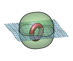
Consider a control volume,  $V$, which contains an interface,
  $I$, between two fluids, as illustrated in figure 2. We separate
  $V$ into two smaller volumes,
  $V_1$ and
  $V_2$ – the portion of
  $V$ in fluid 1 and 2, respectively. The total vector circulation in
  $V$ is expressed as
 \begin{equation} \boldsymbol{\varGamma} = \oint_{\partial V} \boldsymbol{\hat{n}} \times \boldsymbol{u} \,\mathrm{d} S = \int_{V_1} \boldsymbol{\omega}_1 \,\mathrm{d} V + \int_{V_2} \boldsymbol{\omega}_2 \,\mathrm{d} V + \int_I \boldsymbol{\hat{s}} \times (\boldsymbol{u}_2 - \boldsymbol{u}_1) \,\mathrm{d} S,\end{equation}
where  $\boldsymbol {u}_i$ is the velocity of fluid
  $i$. The surface integral in (2.10) represents the density of circulation contained in the interface vortex sheet, due to a tangential slip velocity. The local density of circulation on a section of interface is
 \begin{equation} \boldsymbol{\gamma} = \boldsymbol{\hat{s}} \times (\boldsymbol{u}_2 - \boldsymbol{u}_1), \end{equation}
and the total vector circulation in  $V$ includes vorticity in the fluid interior, and circulation in the interface vortex sheet,
 \begin{equation} \boldsymbol{\varGamma} = \int_V \boldsymbol{\omega} \,\mathrm{d} V + \int_I \boldsymbol{\gamma} \,\mathrm{d} S.\end{equation}
Figure 2. A control volume,  $V$, in an interfacial flow, comprising two sub-volumes,
  $V_1$ and
  $V_2$ – the portion of
  $V$ in each fluid. Here
  $\partial V$ is the outer boundary of
  $V$, with
  $\partial V_i$ being the portion of this boundary in fluid
  $i$;
$i$;  $I$ is the surface of intersection between the interface and
  $V$, with a boundary curve
  $\partial I$;
  $\boldsymbol {\hat {s}}$ is the unit normal to the interface, directed into fluid 2, while
  $\boldsymbol {\hat {n}}$ is the unit normal to the control-volume boundary;
  $\boldsymbol {\hat {t}}$ is the unit tangent to
  $\partial I$; and
  $\boldsymbol {\hat {b}} = \boldsymbol {\hat {t}} \times \boldsymbol {\hat {s}}$ is a unit vector tangent to
  $I$, but orthogonal to
  $\partial I$.
Now, the interface vortex sheet generalises several important kinematic properties of the vorticity field (Terrington et al. Reference Terrington, Hourigan and Thompson2021). First, it satisfies a generalised divergence-free condition for the vorticity field (Terrington et al. Reference Terrington, Hourigan and Thompson2021),
 \begin{equation} \oint_{\partial V} \boldsymbol{\omega} \boldsymbol{\cdot} \mathrm{d} \boldsymbol{S} + \oint_{\partial I} \boldsymbol{\gamma} \boldsymbol{\cdot} \boldsymbol{\hat{b}} \,\mathrm{d} s = 0.\end{equation}
In (2.13),  $\boldsymbol {\gamma } \boldsymbol {\cdot } \boldsymbol {\hat {b}}$ is interpreted as the flux of interface circulation across
  $\partial I$, while
  $\boldsymbol {\omega } \boldsymbol {\cdot } \mathrm {d} \boldsymbol {S}$ represents the flux of vorticity across
  $\partial V$. (Here, flux is analogous to the magnetic flux, and should not be confused with the boundary vorticity flux.) The total flux of vorticity out of a closed surface, including contributions from vorticity in the fluid interior and circulation in the interface, is zero, effectively generalising the divergence-free property of the vorticity field to interfaces with slip. Vortex tubes do not simply end on the interface – they continue either in the fluid on the other side of the interface, or as circulation in the interface vortex sheet.
The interface circulation also generalises the Biot–Savart integral to slip interfaces (Terrington et al. Reference Terrington, Hourigan and Thompson2021),
 \begin{equation} \boldsymbol{u} = \boldsymbol{\nabla} \times \left[\int_V \frac{\boldsymbol{\omega}}{4{\rm \pi} R} \, \mathrm{d} V + \int_I \frac{\boldsymbol{\gamma}}{4{\rm \pi} R}\,\mathrm{d}S \right].\end{equation}
In order to compute the induced velocity field, contributions from the interface vortex sheet are required to capture a velocity discontinuity on the interface.
We also consider the circulation for a control surface,  $S$, which intersects
  $I$, as illustrated in figure 3. Surface
  $S$ is split into two smaller surfaces,
  $S_1$ and
  $S_2$, the portion of
  $S$ in fluids 1 and 2, respectively. The total circulation in
  $S$ is given by
 \begin{equation} \varGamma = \oint_{\partial S} \boldsymbol{u} \boldsymbol{\cdot} \mathrm{d} \boldsymbol{s} = \int_{S_1} \boldsymbol{\omega} \boldsymbol{\cdot} \mathrm{d} \boldsymbol{S} + \int_{S_2} \boldsymbol{\omega} \boldsymbol{\cdot} \mathrm{d} \boldsymbol{S} + \int_I (\boldsymbol{u}_2 - \boldsymbol{u}_1)\boldsymbol{\cdot} \mathrm{d} \boldsymbol{s}.\end{equation}
Now, the final term can be related to the interface circulation,  $\boldsymbol {\gamma } = \boldsymbol {\hat {s}} \times (\boldsymbol {u}_2 - \boldsymbol {u}_1)$, as follows:
 \begin{equation} \int_I (\boldsymbol{u}_2 - \boldsymbol{u}_1)\boldsymbol{\cdot} \mathrm{d} \boldsymbol{s} = \int_I \boldsymbol{\hat{t}}_I \boldsymbol{\cdot} (\boldsymbol{u}_2 - \boldsymbol{u}_1)\,\mathrm{d} s = \int_I (\boldsymbol{\hat{b}} \times \boldsymbol{\hat{s}})\boldsymbol{\cdot} (\boldsymbol{u}_2 - \boldsymbol{u}_1)\, \mathrm{d} s = \int_I \boldsymbol{\gamma} \boldsymbol{\cdot} \boldsymbol{\hat{b}} \,\mathrm{d} s.\end{equation}
In (2.16),  $\boldsymbol {\hat {t}}$ is the unit vector tangent to both
  $S$ and
  $I$,
$I$,  $\boldsymbol {\hat {s}}$ is the unit normal to
  $I$, and
  $\boldsymbol {\hat {b}}$ is the unit vector orthogonal to both
  $\boldsymbol {\hat {s}}$ and
  $\boldsymbol {\hat {t}}$, and is therefore tangent to the interface. The total circulation in
  $S$ includes vorticity in each fluid, and circulation in the interface vortex sheet,
 \begin{equation} \varGamma = \int_S \boldsymbol{\omega} \boldsymbol{\cdot} \mathrm{d} \boldsymbol{S} + \int_I \boldsymbol{\gamma} \boldsymbol{\cdot} \boldsymbol{\hat{b}} \,\mathrm{d} s. \end{equation}
Figure 3. A control surface,  $S$, in a three-dimensional interfacial flow, where
  $S$ comprises two sub-surfaces,
  $S_1$ and
  $S_2$, which are the portions of
  $S$ in each fluid. These sub-surfaces are separated by the curve,
  $I$, which lies in the interface. Here
  $\partial S$ is the outer boundary of
  $S$, with
  $\partial S_i$ being the portion of
  $\partial S$ in fluid
  $i$. The following unit vectors are used:
  $\boldsymbol {\hat {n}}$ is the unit normal to
  $S$, while
  $\boldsymbol {\hat {s}}$ is the unit normal to the interface;
  $\boldsymbol {\hat {t}}_I$ and
  $\boldsymbol {\hat {t}}_S$ are the unit tangent vectors to
  $I$ and
  $\partial S$, respectively;
  $\boldsymbol {\hat {m}}_S = \boldsymbol {\hat {t}}_S \times \boldsymbol {\hat {n}}$ is a unit vector tangent to
  $S$, but orthogonal to
  $\partial S$; while
  $\boldsymbol {\hat {m}}_I = \boldsymbol {\hat {t}}_I \times \boldsymbol {\hat {n}}$ is a unit vector normal to
  $I$, but tangent to
  $S$. Finally,
  $\boldsymbol {\hat {b}} = \boldsymbol {\hat {s}} \times \boldsymbol {\hat {t}}_I$ is a unit vector normal to
  $I$, but tangent to the interface.
2.3. The total vorticity balance in three dimensions
We now derive the vector-circulation balance for a three-dimensional interfacial flow. To begin, consider the time derivative of (2.12),
 \begin{equation} \frac{\mathrm{d} \boldsymbol{\varGamma}}{\mathrm{d} t} = \frac{\mathrm{d} }{\mathrm{d} t} \int_V \boldsymbol{\omega} \,\mathrm{d} V + \frac{\mathrm{d} }{\mathrm{d} t} \int_I \boldsymbol{\gamma} \,\mathrm{d} S. \end{equation}
We first consider the integral over  $V$. From 2.4, the rate of change of vorticity in fluid
  $i$ is
 \begin{align} \frac{\mathrm{d} \boldsymbol{\varGamma}_i}{\mathrm{d} t} = \frac{\mathrm{d} }{\mathrm{d} t}\int_{V_i} \boldsymbol{\omega} \,\mathrm{d} V &= \int_{\partial V_i} \boldsymbol{\omega} (\boldsymbol{v}^{b} -\boldsymbol{u} ) \boldsymbol{\cdot} \boldsymbol{\hat{n}} \,\mathrm{d} S + \int_{\partial V_i} (\boldsymbol{\omega} \boldsymbol{\cdot} \boldsymbol{\hat{n}} )\boldsymbol{u} \,\mathrm{d} S - \int_{\partial V_i} \nu \boldsymbol{\hat{n}} \times (\boldsymbol{\nabla} \times \boldsymbol{\omega})\,\mathrm{d} S\nonumber\\ &\quad \pm \int_{I} (\boldsymbol{\omega}_i \boldsymbol{\cdot} \boldsymbol{\hat{s}} )\boldsymbol{u}_i \,\mathrm{d} S \mp \int_{I} \nu \boldsymbol{\hat{s}} \times (\boldsymbol{\nabla} \times \boldsymbol{\omega}_i) \,\mathrm{d} S, \end{align}
where  $\partial V_i$ is the portion of
  $\partial V$ in fluid
  $i$. The
  $\pm$ symbol indicates a term that is positive for
  $i = 1$ and negative for
  $i = 2$, while
  $\mp$ indicates a term that is negative for
  $i = 1$ and positive for
  $i = 2$.
This result is substituted into (2.18) to obtain the following expression:
 \begin{align} \frac{\mathrm{d} \boldsymbol{\varGamma}}{\mathrm{d} t} &= \frac{\mathrm{d} }{\mathrm{d} t}\int_I \boldsymbol{\gamma} \,\mathrm{d} S + \oint_{\partial V} \boldsymbol{\omega} (\boldsymbol{v}^{b} -\boldsymbol{u} ) \boldsymbol{\cdot} \boldsymbol{\hat{n}} \,\mathrm{d} S + \oint_{\partial V} (\boldsymbol{\omega} \boldsymbol{\cdot} \boldsymbol{\hat{n}} )\boldsymbol{u}\, \mathrm{d} S - \oint_{\partial V} \nu \boldsymbol{\hat{n}} \times (\boldsymbol{\nabla} \times \boldsymbol{\omega})\,\mathrm{d} S\nonumber\\ &\quad + \int_I [\kern-1pt[ \boldsymbol{\omega} (\boldsymbol{v}^{b} - \boldsymbol{u}) \boldsymbol{\cdot} \boldsymbol{\hat{s}} ]\kern-1pt] \,\mathrm{d} S - \int_I [\kern-1pt[ (\boldsymbol{\omega} \boldsymbol{\cdot} \boldsymbol{\hat{s}} ) \boldsymbol{u} ]\kern-1pt] \,\mathrm{d} S + \int_I [\kern-1pt[ \boldsymbol{\hat{s}} \times (\boldsymbol{\nabla} \times \boldsymbol{\omega}) ]\kern-1pt] \,\mathrm{d} S. \end{align}
In (2.20), integrals over  $\partial V$ describe fluxes of vorticity out of the control-volume boundary in the fluid interior, while integrals over
  $I$ indicate the fluxes of vorticity out of the interface and into the fluid interior.
We now construct an expression for the rate of change of interface circulation. First, the interface circulation is split into contributions from the upper and lower fluids,
 \begin{equation} \frac{\mathrm{d} }{\mathrm{d} t} \int_I \boldsymbol{\gamma} \,\mathrm{d} S = \frac{\mathrm{d} }{\mathrm{d} t} \int_I \boldsymbol{\hat{s}} \times \boldsymbol{u}_2 \,\mathrm{d} S - \frac{\mathrm{d} }{\mathrm{d} t} \int_I \boldsymbol{\hat{s}} \times \boldsymbol{u}_1 \,\mathrm{d} S.\end{equation}
We assume that the surface  $I$ can be parametrised as
  $\boldsymbol {y}(u,v,t)$, so the domain of integration is constant in time when expressed in terms of
  $u$ and
  $v$. The integrals in (2.21) then become
 \begin{equation} \frac{\mathrm{d} }{\mathrm{d} t}\int_I \boldsymbol{\hat{s}}\times \boldsymbol{u}_i \,\mathrm{d} S = \frac{\mathrm{d} }{\mathrm{d} t} \int_I \mathrm{d} \boldsymbol{S} \times \boldsymbol{u}_i = \left.\int_I \frac{\partial }{\partial t}(\mathrm{d} \boldsymbol{S})\right|_{(u,v)}\!\times \boldsymbol{u}_i + \left.\int_I \mathrm{d} \boldsymbol{S} \times \frac{\partial \boldsymbol{u}}{\partial t}\right|_{(u,v)},\end{equation}
where partial derivatives are with respect to a constant  $(u,v)$. Letting
  $\boldsymbol {v}^{b} = \partial {\boldsymbol {y}}/\partial t$ be the velocity of a constant
  $(u,v)$ reference point, the partial derivative of
  $u$ can be written as
 \begin{equation} \left.\frac{\partial \boldsymbol{u}}{\partial t}\right|_{(u,v)} = \frac{\mathrm{d} \boldsymbol{u}}{\mathrm{d} t} + (\boldsymbol{v}^{b} - \boldsymbol{u})\boldsymbol{\cdot} \boldsymbol{\nabla} \boldsymbol{u}.\end{equation}
Then, the second term in (2.22) becomes
 \begin{equation} \left.\int_I \mathrm{d} \boldsymbol{S} \times \frac{\partial \boldsymbol{u}}{\partial t}\right|_{(u,v)} = \int_I \boldsymbol{\hat{s}} \times \frac{\mathrm{d} \boldsymbol{u}}{\mathrm{d} t} \mathrm{d} S + \int_I \boldsymbol{\hat{s}} \times (\boldsymbol{v}^{b} \boldsymbol{\cdot} \boldsymbol{\nabla} \boldsymbol{u})\,\mathrm{d} S - \int_I \boldsymbol{\hat{s}} \times (\boldsymbol{u} \boldsymbol{\cdot} \boldsymbol{\nabla} \boldsymbol{u})\,\mathrm{d} S. \end{equation}
Finally, the advection term is expressed as
 \begin{equation} \boldsymbol{u} \boldsymbol{\cdot} \boldsymbol{\nabla} \boldsymbol{u} = \boldsymbol{\nabla} (\tfrac{1}{2}\boldsymbol{u} \boldsymbol{\cdot} \boldsymbol{u}) - \boldsymbol{u} \times \boldsymbol{\omega},\end{equation}
and we have
 \begin{equation} \int_I \boldsymbol{\hat{s}} \times (\boldsymbol{u} \boldsymbol{\cdot} \boldsymbol{\nabla} \boldsymbol{u}) \,\mathrm{d} S = \oint_I \tfrac{1}{2} \boldsymbol{u} \boldsymbol{\cdot} \boldsymbol{u} \,\mathrm{d} \boldsymbol{s} - \int_I (\boldsymbol{\hat{s}} \boldsymbol{\cdot} \boldsymbol{\omega}) \boldsymbol{u} \,\mathrm{d} S + \int_I (\boldsymbol{\hat{s}} \boldsymbol{\cdot} \boldsymbol{u}) \boldsymbol{\omega} \,\mathrm{d} S. \end{equation}
 If we assume that  $\boldsymbol {v}^{b}$ can be extended into a three-dimensional neighbourhood of
  $I$, the rate of change of the surface-area element is (Batchelor Reference Batchelor1967):
 \begin{equation} \left.\frac{\partial }{\partial t}(\mathrm{d} \boldsymbol{S})\right|_{(u,v)} = (\boldsymbol{\nabla} \boldsymbol{\cdot} \boldsymbol{v}^{b} ) \,\mathrm{d} \boldsymbol{S} - (\boldsymbol{\nabla} \boldsymbol{v}^{b}) \boldsymbol{\cdot} \mathrm{d} \boldsymbol{S}. \end{equation}
Strictly speaking,  $\boldsymbol {v}^{b}$ is only defined on
  $I$. By decomposing the gradient operator into surface-normal and surface-tangential components (Wu Reference Wu1995), (2.27) can be expressed in terms of quantities defined only on
  $I$:
$I$:
 \begin{equation} \left.\frac{\partial }{\partial t}(\mathrm{d} \boldsymbol{S})\right|_{(u,v)}= (\boldsymbol{\nabla}_S \boldsymbol{\cdot} \boldsymbol{v}^{b} ) \,\mathrm{d} \boldsymbol{S} - (\boldsymbol{\nabla}_S \boldsymbol{v}^{b}) \boldsymbol{\cdot} \mathrm{d} \boldsymbol{S}, \end{equation}
where  $\boldsymbol {\nabla }_S$ is the surface gradient operator (Wu Reference Wu1995). For convenience, however, we use (2.27), assuming that
  $\boldsymbol {v}^{b}$ can be extended to a three-dimensional neighbourhood of
  $I$. The first integral in (2.22) then becomes
 \begin{equation} \left.\int_I \frac{\partial }{\partial t}(\mathrm{d} \boldsymbol{S})\right|_{(u,v)} \!\times \boldsymbol{u} = \int_I [(\boldsymbol{\nabla} \boldsymbol{\cdot} \boldsymbol{v}^{b})\boldsymbol{\hat{s}} - (\boldsymbol{\nabla} \boldsymbol{v}^{b})\boldsymbol{\cdot} \boldsymbol{\hat{s}}] \times \boldsymbol{u} \,\mathrm{d} S.\end{equation}
The first term in the integrand can be written as
 \begin{equation} (\boldsymbol{\nabla} \boldsymbol{\cdot} \boldsymbol{v}^{b})\boldsymbol{\hat{s}} \times \boldsymbol{u} = \boldsymbol{\hat{s}} \times (\boldsymbol{\nabla} \boldsymbol{\cdot} (\boldsymbol{v}^b \boldsymbol{u})) - \boldsymbol{\hat{s}} \times (\boldsymbol{v}^{b} \boldsymbol{\cdot} \boldsymbol{\nabla} \boldsymbol{u}), \end{equation}
while the second term is
 \begin{equation} \boldsymbol{u} \times ( (\boldsymbol{\nabla} \boldsymbol{v}^{b}) \boldsymbol{\cdot} \boldsymbol{\hat{s}} ) = \boldsymbol{\omega} (\boldsymbol{v}^{b} \boldsymbol{\cdot} \boldsymbol{\hat{s}}) - (\boldsymbol{\nabla} \times (\boldsymbol{u} \boldsymbol{v}^{b})) \boldsymbol{\cdot} \boldsymbol{\hat{s}}. \end{equation}
Finally, combining various terms from (2.22)–(2.31) gives
 \begin{align} \frac{\mathrm{d} }{\mathrm{d} t}\int_I \boldsymbol{\hat{s}} \times \boldsymbol{u} \,\mathrm{d} S &= \int_I \boldsymbol{\hat{s}} \times \frac{\mathrm{d} \boldsymbol{u}}{\mathrm{d} t}\, \mathrm{d} S + \int_I (\boldsymbol{\hat{s}} \boldsymbol{\cdot} \boldsymbol{\omega})\boldsymbol{u} \,\mathrm{d} S - \oint_{\partial I} \frac{1}{2} \boldsymbol{u} \boldsymbol{\cdot} \boldsymbol{u} \,\mathrm{d} \boldsymbol{s} + \int_I \boldsymbol{\hat{s}} \boldsymbol{\cdot} (\boldsymbol{v}^{b} - \boldsymbol{u} )\boldsymbol{\omega} \,\mathrm{d}S \nonumber\\ &\quad + \int_I \boldsymbol{\hat{s}} \times (\boldsymbol{\nabla} \boldsymbol{\cdot} (\boldsymbol{v}^{b} \boldsymbol{u}))\,\mathrm{d} S - \int_I (\boldsymbol{\nabla} \times (\boldsymbol{u} \boldsymbol{v}^{b})) \boldsymbol{\cdot} \boldsymbol{\hat{s}} \,\mathrm{d} S. \end{align}
The final two terms in (2.32) are related to stretching, translation and rotation of the interface. These terms are further simplified using the relationship
 \begin{equation} \boldsymbol{\hat{s}} \times (\boldsymbol{\nabla} \boldsymbol{\cdot} (\boldsymbol{v}^{b} \boldsymbol{u}) ) - (\boldsymbol{\nabla} \times (\boldsymbol{u} \boldsymbol{v}^{b})) \boldsymbol{\cdot} \boldsymbol{\hat{s}} = \boldsymbol{\hat{s}} \times \boldsymbol{\nabla} (\boldsymbol{u} \boldsymbol{\cdot} \boldsymbol{v}^{b}) - \boldsymbol{\hat{s}} \boldsymbol{\cdot} (\boldsymbol{\nabla} \times (\boldsymbol{u} \boldsymbol{v}^{b})),\end{equation}
which can be verified by explicitly expanding all terms in Cartesian coordinates. Surface integrals of these terms are exact, giving
 \begin{align} \int_I \boldsymbol{\hat{s}} \times (\boldsymbol{\nabla} (\boldsymbol{v}^{b}\boldsymbol{\cdot}\boldsymbol{u})) \mathrm{d} S - \int_I \boldsymbol{\nabla} \times (\boldsymbol{u} \boldsymbol{v}^{b})\boldsymbol{\cdot} \mathrm{d} \boldsymbol{S} &= \oint_{\partial I} [ (\boldsymbol{u} \boldsymbol{\cdot} \boldsymbol{v}^{b}) \boldsymbol{\hat{t}} - \boldsymbol{v}^{b}(\boldsymbol{u} \boldsymbol{\cdot} \boldsymbol{\hat{t}})] \, \mathrm{d} s \nonumber\\ &={-}\oint_{\partial I} \boldsymbol{u} \times (\boldsymbol{v}^{b} \times \boldsymbol{\hat{t}}) \,\mathrm{d} s, \end{align}
where  $\boldsymbol {\hat {t}}$ is the unit tangent to
  $\partial I$. Equation (2.32) becomes
 \begin{equation} \frac{\mathrm{d} }{\mathrm{d} t}\int_I \boldsymbol{\hat{s}} \times \boldsymbol{u} \,\mathrm{d} S = \int_I \boldsymbol{\hat{s}} \times \frac{\mathrm{d} \boldsymbol{u}}{\mathrm{d} t}\,\mathrm{d} S + \int_I (\boldsymbol{\hat{s}} \boldsymbol{\cdot} \boldsymbol{\omega})\boldsymbol{u} \,\mathrm{d} S - \oint_{\partial I} \frac{1}{2} \boldsymbol{u} \boldsymbol{\cdot} \boldsymbol{u} \,\mathrm{d} \boldsymbol{s} - \oint_{\partial I} \boldsymbol{u} \times (\boldsymbol{v}^{b } \times \boldsymbol{\hat{t}}) \,\mathrm{d}s,\end{equation}
where we have used  $(\boldsymbol {v}^{b}-\boldsymbol {u}) \boldsymbol {\cdot } \boldsymbol {\hat {s}} = 0$. Finally, substituting this result into (2.21) gives an expression for the rate of change of interface circulation:
 \begin{align} \frac{\mathrm{d} }{\mathrm{d} t}\int_I \boldsymbol{\gamma} \,\mathrm{d} S &= \int_I \boldsymbol{\hat{s}} \times
[[ \frac{\mathrm{d} \boldsymbol{u}}{\mathrm{d} t} ]] \mathrm{d} S + \int_I [\kern-1pt[ (\boldsymbol{\hat{s}} \boldsymbol{\cdot} \boldsymbol{\omega}) \boldsymbol{u} ]\kern-1pt] \mathrm{d} S - \oint_{\partial I} \frac{1}{2}[\kern-1pt[ \boldsymbol{u} \boldsymbol{\cdot} \boldsymbol{u} ]\kern-1pt] \,\mathrm{d} \boldsymbol{s} \nonumber\\ & \quad -\oint_{\partial I} [\kern-1pt[ \boldsymbol{u} \times (\boldsymbol{v}^{b} \times \boldsymbol{\hat{t}})]\kern-1pt] \,\mathrm{d} s. \end{align}
\begin{align} \frac{\mathrm{d} }{\mathrm{d} t}\int_I \boldsymbol{\gamma} \,\mathrm{d} S &= \int_I \boldsymbol{\hat{s}} \times
[[ \frac{\mathrm{d} \boldsymbol{u}}{\mathrm{d} t} ]] \mathrm{d} S + \int_I [\kern-1pt[ (\boldsymbol{\hat{s}} \boldsymbol{\cdot} \boldsymbol{\omega}) \boldsymbol{u} ]\kern-1pt] \mathrm{d} S - \oint_{\partial I} \frac{1}{2}[\kern-1pt[ \boldsymbol{u} \boldsymbol{\cdot} \boldsymbol{u} ]\kern-1pt] \,\mathrm{d} \boldsymbol{s} \nonumber\\ & \quad -\oint_{\partial I} [\kern-1pt[ \boldsymbol{u} \times (\boldsymbol{v}^{b} \times \boldsymbol{\hat{t}})]\kern-1pt] \,\mathrm{d} s. \end{align}The first term in (2.36) is the relative tangential acceleration of fluid elements on each side of the interface. This may be substituted for the momentum equation,
 \begin{equation} \int_I \boldsymbol{\hat{s}} \times[[ \frac{\mathrm{d} \boldsymbol{u}}{\mathrm{d} t} ]] \mathrm{d} S ={-}\oint_{\partial I} [[ \frac{p}{\rho} + \varPhi_g ]] \mathrm{d} \boldsymbol{s} - \int_I [\kern-1pt[ \nu \boldsymbol{\hat{s}} \times (\boldsymbol{\nabla} \times \boldsymbol{\omega} )]\kern-1pt] \,\mathrm{d} S,\end{equation}
where  $\varPhi _g$ is the body-force potential. The first term in (2.37) describes the effects of inviscid forces: tangential pressure gradients and body forces. The final term describes the effects of viscous forces, and is equal to the viscous flux of vorticity out of the interface.
Equations (2.36) and (2.37) can be substituted into (2.20), giving the following expression for the rate of change of vector circulation in  $V$:
$V$:
 \begin{align} \frac{\mathrm{d} \boldsymbol{\varGamma}}{\mathrm{d} t} &= \oint_{\partial V} \boldsymbol{\omega} (\boldsymbol{v}^{b} - \boldsymbol{u}) \boldsymbol{\cdot} \boldsymbol{\hat{n}} \,\mathrm{d} S + \oint_{\partial V} (\boldsymbol{\omega} \boldsymbol{\cdot} \boldsymbol{\hat{n}} )\boldsymbol{u} \,\mathrm{d} S - \oint_{\partial V} \nu \boldsymbol{\hat{n}} \times (\boldsymbol{\nabla} \times \boldsymbol{\omega})\,\mathrm{d} S \nonumber\\ &\quad - \oint_{\partial I} [[ \frac{p}{\rho} + \varPhi_g]]\mathrm{d} \boldsymbol{s} -\oint_{\partial I} \frac{1}{2}[\kern-1pt[ \boldsymbol{u} \boldsymbol{\cdot} \boldsymbol{u}]\kern-1pt] \,\mathrm{d} \boldsymbol{s} - \oint_{\partial I} [\kern-1pt[ \boldsymbol{u} \times (\boldsymbol{v}^{b} \times \boldsymbol{\hat{t}})]\kern-1pt] \,\mathrm{d} s. \end{align}
The circulation balance in (2.38) is expressed entirely in terms of vorticity fluxes across the outer boundary, either through the fluid interior ( $\partial V$) or along the interface (
 $\partial I$). These fluxes include the effects of advection (
 $\boldsymbol {\omega } (\boldsymbol {v}^{b} - \boldsymbol {u}) \boldsymbol {\cdot } \boldsymbol {\hat {n}}$), vortex stretching/tilting (
 $(\boldsymbol {\omega } \boldsymbol {\cdot } \boldsymbol {\hat {n}}) \boldsymbol {u}$) and viscous diffusion (
 $\nu \boldsymbol {\hat {n}} \times (\boldsymbol {\nabla } \times \boldsymbol {\omega })$) in the fluid interior (
 $\partial V$), as well as fluxes of circulation at the interface (
 $\partial I$), by advection (
 $\frac {1}{2} [\kern-1pt[ \boldsymbol {u} \boldsymbol {\cdot } \boldsymbol {u} ]\kern-1pt]$) and a term related to motion of the interface (
 $[\kern-1pt[ \boldsymbol {u} \times (\boldsymbol {v}^{b} \times \boldsymbol {\hat {t}})]\kern-1pt]$). Finally, circulation may be created on the interface by the inviscid relative acceleration, by either tangential pressure gradients (
 $p/\rho$) or body forces (
 $\varPhi _g$).
The pressure and body-force terms in (2.38) can also be interpreted as contributing to the transport of circulation along the interface (e.g. Lundgren & Koumoutsakos Reference Lundgren and Koumoutsakos1999), rather than the creation of vorticity at the interface. However, these are the only terms in (2.38) that can result in the appearance of vorticity in an initially irrotational flow (where both  $\boldsymbol {\omega }$ and
  $\boldsymbol {\gamma }$ are zero everywhere). Therefore, consistent with past discussions on vorticity dynamics (Lighthill Reference Lighthill1963; Morton Reference Morton1984; Terrington et al. Reference Terrington, Hourigan and Thompson2020), we prefer to interpret these terms as representing the creation of circulation on the interface, by the inviscid relative acceleration between fluid elements on each side of the interface. Note that the net vorticity creation rate depends only on the pressure or body-force potential on the boundary (
 $\partial I$), so when there is no external pressure gradient or body force, the net generation of vorticity on the interface is zero – local creation of vorticity on some portion of
  $I$ will be balanced by equal generation of opposite-signed vorticity elsewhere.
The viscous boundary vorticity flux at the interface,  $[\kern-1pt[ \nu \boldsymbol {\hat {s}} \times (\boldsymbol {\nabla } \times \boldsymbol {\omega })]\kern-1pt]$, does not appear in (2.38), and therefore plays no role in the generation of vorticity. This term provides equal and opposite contributions to the rate of change of vorticity in the fluid interior (2.19) and the interface circulation (2.37), and therefore acts to transfer circulation between the interface vortex sheet and the fluid interior, without generating a net circulation.
Similarly, the vortex stretching/tilting flux on the interface,  $[\kern-1pt[ (\boldsymbol {\omega } \boldsymbol {\cdot } \boldsymbol {\hat {s}}) \boldsymbol {u}]\kern-1pt]$, does not appear in (2.38). This term provides equal and opposite contributions to (2.19) and (2.36), and therefore does not generate a net circulation on the interface. The increase in circulation in the interface vortex sheet due to vortex stretching and tilting is balanced by an equal and opposite change to the vorticity in the fluid interior, with the total circulation remaining constant. We discuss the physical interpretation of this term in more detail in § 3.
2.4. Conservation of circulation in a control surface
We also construct a control-surface conservation law for circulation in an interfacial flow. The time derivative of (2.17) is
 \begin{equation} \frac{\mathrm{d} \varGamma}{\mathrm{d} t} = \frac{\mathrm{d} }{\mathrm{d} t}\int_S \boldsymbol{\omega} \boldsymbol{\cdot} \mathrm{d} \boldsymbol{S} + \frac{\mathrm{d} }{\mathrm{d} t} \int_I \boldsymbol{\gamma} \boldsymbol{\cdot} \boldsymbol{\hat{b}} \,\mathrm{d} S. \end{equation}
 Then, using (2.9), the rate of change of circulation in  $S_i$ is
 \begin{align} \frac{\mathrm{d} \varGamma_i}{\mathrm{d} t} &= \int_{\partial S_i} \{\boldsymbol{\hat{m}}_S \times [(\boldsymbol{u} - \boldsymbol{v}^{b})\times \boldsymbol{\omega} - \nu (\boldsymbol{\nabla} \times \boldsymbol{\omega})]\} \boldsymbol{\cdot} \boldsymbol{\hat{n}} \,\mathrm{d} s \nonumber\\ &\quad \pm \int_I \{\boldsymbol{\hat{m}}_I \times[(\boldsymbol{u}_i - \boldsymbol{v}^{b}) \times \boldsymbol{\omega}_i - \nu (\boldsymbol{\nabla} \times \boldsymbol{\omega}_i)]\}\boldsymbol{\cdot} \boldsymbol{\hat{n}} \,\mathrm{d} s, \end{align}
where the integral over  $I$ is positive in fluid 1 (
 $i = 1$) and negative in fluid 2 (
 $i = 2$). Substituting this result into (2.39) gives the following expression:
 \begin{align} \frac{\mathrm{d} \varGamma}{\mathrm{d} t} &= \frac{\mathrm{d} }{\mathrm{d} t}\int_I \boldsymbol{\gamma} \boldsymbol{\cdot} \boldsymbol{\hat{b}} \,\mathrm{d} s + \oint_{\partial S} \{\boldsymbol{\hat{m}}_S \times [(\boldsymbol{u} - \boldsymbol{v}^{b})\times \boldsymbol{\omega} - \nu (\boldsymbol{\nabla} \times \boldsymbol{\omega})]\} \boldsymbol{\cdot} \boldsymbol{\hat{n}} \,\mathrm{d} s \nonumber\\ &\quad - \int_I [\kern-1pt[ (\boldsymbol{\hat{m}}_I \times (\boldsymbol{u} - \boldsymbol{v}^{b}) \times \boldsymbol{\omega}) \boldsymbol{\cdot} \boldsymbol{\hat{n}} ]\kern-1pt] \, \mathrm{d} s + \int_I [\kern-1pt[ \nu ( \boldsymbol{\hat{m}}_I \times (\boldsymbol{\nabla} \times \boldsymbol{\omega}) )\boldsymbol{\cdot} \boldsymbol{\hat{n}} ]\kern-1pt] \mathrm{d} s. \end{align}
The rate of change of interface circulation can be separated into contributions from the upper and lower fluids, using (2.16):
 \begin{equation} \frac{\mathrm{d} }{\mathrm{d} t}\int_I \boldsymbol{\gamma} \boldsymbol{\cdot} \boldsymbol{\hat{b}} \,\mathrm{d} s = \frac{\mathrm{d} }{\mathrm{d} t} \int_I \boldsymbol{u}_2 \boldsymbol{\cdot} \mathrm{d} \boldsymbol{s} - \frac{\mathrm{d} }{\mathrm{d} t} \int_I \boldsymbol{u}_1 \boldsymbol{\cdot} \mathrm{d} \boldsymbol{s}.\end{equation}
If the curve,  $I$, is parametrised as
  $\boldsymbol {y}(s',t)$, where the bounds of integration in terms of
  $s'$ are constant in time, then we have
 \begin{equation} \frac{\mathrm{d} }{\mathrm{d} t} \int_I \boldsymbol{u} \boldsymbol{\cdot} \mathrm{d} \boldsymbol{s} = \left.\int_I \frac{\partial \boldsymbol{u}}{\partial t} \right|_{s'} \! \boldsymbol{\cdot} \mathrm{d} \boldsymbol{s} + \int_I \boldsymbol{u} \boldsymbol{\cdot} \frac{\partial^2 \boldsymbol{y}} {\partial t \partial s'} \, \mathrm{d} s' = \left.\int_I \frac{\partial \boldsymbol{u}}{\partial t} \right|_{s'} \! \boldsymbol{\cdot} \mathrm{d} \boldsymbol{s} + \int_I \boldsymbol{u} \boldsymbol{\cdot} \frac{\partial \boldsymbol{v}^{b}}{\partial s} \,\mathrm{d} s, \end{equation}
where  $\partial \boldsymbol {y} /\partial t = \boldsymbol {v}^{b}$. The partial derivative with respect to a fixed
  $s'$ can instead be expressed in terms of the material derivative,
 \begin{equation} \left.\int_I \frac{\partial \boldsymbol{u}}{\partial t} \right|_{s'} \!\boldsymbol{\cdot} \mathrm{d} \boldsymbol{s} = \int_I \frac{\mathrm{d} \boldsymbol{u}}{\mathrm{d} t} \boldsymbol{\cdot} \mathrm{d} \boldsymbol{s} + \int_I [ (\boldsymbol{v}^{b} - \boldsymbol{u}) \boldsymbol{\cdot} \boldsymbol{\nabla} \boldsymbol{u} ] \boldsymbol{\cdot} \mathrm{d} \boldsymbol{s}. \end{equation}
The advection term can be expressed in the form
 \begin{equation} \int_I (\boldsymbol{u} \boldsymbol{\cdot} \boldsymbol{\nabla} \boldsymbol{u})\boldsymbol{\cdot} \mathrm{d} \boldsymbol{s} = \frac{1}{2} \int_I \boldsymbol{\nabla} (\boldsymbol{u} \boldsymbol{\cdot} \boldsymbol{u}) \boldsymbol{\cdot} \mathrm{d} \boldsymbol{s}- \int_I (\boldsymbol{u} \times \boldsymbol{\omega} )\boldsymbol{\cdot} \mathrm{d} \boldsymbol{s} = \frac{1}{2} (\boldsymbol{u} \boldsymbol{\cdot} \boldsymbol{u}) _{(b-a)} - \int_I (\boldsymbol{u} \times \boldsymbol{\omega} )\boldsymbol{\cdot} \mathrm{d} \boldsymbol{s}, \end{equation}
where subscript  $(b-a)$ indicates the difference in function values at the endpoints of
  $I$ (
$I$ ( $\theta _{(b-a)} = \theta _b - \theta _a$). Collecting terms involving
  $\boldsymbol {v}^{b}$, we have
 \begin{equation} \int_I [\boldsymbol{v}^{b} \boldsymbol{\cdot}( \boldsymbol{\nabla} \boldsymbol{u} )\boldsymbol{\cdot} \boldsymbol{\hat{t}}_I + \boldsymbol{\hat{t}}_I \boldsymbol{\cdot} (\boldsymbol{\nabla} \boldsymbol{v}^{b} )\boldsymbol{\cdot} \boldsymbol{u}] \,\mathrm{d} s = \int_I [ \boldsymbol{v}^{b} \boldsymbol{\cdot} \boldsymbol{\nabla} \boldsymbol{u} + (\boldsymbol{\nabla} \boldsymbol{v}^{b}) \boldsymbol{\cdot} \boldsymbol{u} ] \boldsymbol{\cdot} \mathrm{d} \boldsymbol{s}.\end{equation}
Then, using the product rule, this expression becomes
 \begin{equation} \int_I [\boldsymbol{v}^{b} \boldsymbol{\cdot} \boldsymbol{\nabla} \boldsymbol{u} - (\boldsymbol{\nabla} \boldsymbol{u}) \boldsymbol{\cdot} \boldsymbol{v}^{b} + \boldsymbol{\nabla}(\boldsymbol{v}^{b}\boldsymbol{\cdot} \boldsymbol{u}) ] \boldsymbol{\cdot} \mathrm{d} \boldsymbol{s} = \int_I (\boldsymbol{\omega} \times \boldsymbol{v}^{b}) \boldsymbol{\cdot} \mathrm{d} \boldsymbol{s} + (\boldsymbol{u} \boldsymbol{\cdot} \boldsymbol{v}^{b})_{(b-a)}.\end{equation}
Finally, (2.43)–(2.47) are substituted into (2.42), providing the following expression for the rate of change of interface circulation:
 \begin{align} \frac{\mathrm{d} }{\mathrm{d} t} \int_I \boldsymbol{\gamma} \boldsymbol{\cdot} \boldsymbol{\hat{b}} \,\mathrm{d} s &= \int_I [[ \frac{\mathrm{d} \boldsymbol{u}}{\mathrm{d} t} ]]\boldsymbol{\cdot} \mathrm{d} \boldsymbol{s} + \int_I [\kern-1pt[ [\boldsymbol{\hat{m}}_I \times ( (\boldsymbol{u} - \boldsymbol{v}^{b}) \times \boldsymbol{\omega} )] \boldsymbol{\cdot} \boldsymbol{\hat{n}} ]\kern-1pt] \mathrm{d} s \nonumber\\ &\quad - \frac{1}{2} [\kern-1pt[ \boldsymbol{u} \boldsymbol{\cdot} \boldsymbol{u} ]\kern-1pt] _{(b-a)} + [\kern-1pt[ \boldsymbol{u} \boldsymbol{\cdot} \boldsymbol{v}^{b} ]\kern-1pt]_{(b-a)}. \end{align}
 As in (2.36), the term  $[\kern-1pt[ \mathrm {d} \boldsymbol {u}/\mathrm {d} t]\kern-1pt]$ describes changes to the interface circulation due to the relative acceleration between fluid elements on each side of the interface. Using the momentum equation, this is expressed as
 \begin{equation} \int_I [[ \frac{\mathrm{d} \boldsymbol{u}}{\mathrm{d} t} ]]\boldsymbol{\cdot} \mathrm{d} \boldsymbol{s} ={-} [[ \frac{p}{\rho} + \varPhi_g ]]_{(b-a)} - \int_I [\kern-1pt[\nu (\boldsymbol{\hat{m}}_I \times (\boldsymbol{\nabla} \times \boldsymbol{\omega}))\boldsymbol{\cdot} \boldsymbol{\hat{n}} ]\kern-1pt] \mathrm{d} s,\end{equation}
and includes contributions from inviscid forces (pressure and body forces), as well as viscosity.
After substituting (2.49) and (2.42) into (2.41), we have an expression for the conservation of circulation for a control surface in a three-dimensional interfacial flow:
 \begin{align} \frac{\mathrm{d} \varGamma}{\mathrm{d} t} &= \oint_{\partial S}\{ \boldsymbol{\hat{m}}_S \times [(\boldsymbol{u} - \boldsymbol{v}^{b})\times \boldsymbol{\omega} - \nu (\boldsymbol{\nabla} \times \boldsymbol{\omega})] \} \boldsymbol{\cdot} \boldsymbol{\hat{n}} \,\mathrm{d} s - [[ \frac{p}{\rho} + \varPhi_g]]_{(b-a)} \nonumber\\ &\quad - \frac{1}{2} [\kern-1pt[ \boldsymbol{u} \boldsymbol{\cdot} \boldsymbol{u} ]\kern-1pt] _{(b-a)} + [\kern-1pt[ \boldsymbol{u} \boldsymbol{\cdot} \boldsymbol{v}^{b} ]\kern-1pt]_{(b-a)}. \end{align}
The total circulation in  $S$ may change either by the transport of vorticity across the outer boundary (
 $\partial S$) by advection and viscous diffusion, by the transport of circulation along the interface (
 $\boldsymbol {u} \boldsymbol {\cdot } \boldsymbol {u}$ and
  $\boldsymbol {v}^{b} \boldsymbol {\cdot } \boldsymbol {u}$), or by the creation of vorticity due to tangential pressure gradients (
 $p/\rho$) or body forces (
 $\varPhi _g$).
As in the control-volume formulation, the viscous boundary vorticity flux,  $\nu (\boldsymbol {\hat {m}}_I \times (\boldsymbol {\nabla } \times \boldsymbol {\omega }) ) \boldsymbol {\cdot } \boldsymbol {\hat {n}}$, does not appear in (2.50). This term provides equal and opposite contributions to (2.40) and (2.48), and therefore acts to transfer circulation between the interface vortex sheet and the fluid interior, without generating a net circulation.
Similarly, the interface advection term,  $(\boldsymbol {\hat {m}}_I \times (\boldsymbol {u} - \boldsymbol {v}^{b}) \times \boldsymbol {\omega }) \boldsymbol {\cdot } \boldsymbol {\hat {n}}$ – which describes the effects of both advection and vortex stretching/tilting – also provides equal and opposite contributions to (2.40) and (2.48), and therefore does not generate a net circulation. A physical interpretation of this process is presented in § 3.
2.5. Summary of the formulation
We now provide a summary of our three-dimensional formulation of interfacial vorticity dynamics, and compare it to our two-dimensional formulation (Terrington et al. Reference Terrington, Hourigan and Thompson2020). For a two-dimensional flow, both (2.38) and (2.50) reduce to (1.2), and therefore both expressions generalise our two-dimensional formulation to three dimensions. Equation (2.38) describes the conservation of volume-integrated vorticity in a three-dimensional region, while (2.50) describes the conservation of circulation in a two-dimensional reference surface.
Our three-dimensional formulation directly extends Morton's (Reference Morton1984) inviscid description of vorticity creation to three-dimensional interfacial flows. The only mechanism by which vorticity is created on an interface is the inviscid relative acceleration between fluid elements on each side of the interface, by either tangential pressure gradients or body forces. Viscous forces do not create vorticity on the interface, but are responsible for transferring circulation between the interface vortex sheet and the fluid interior.
The effects of vortex stretching and tilting do not appear in the two-dimensional description. In the three-dimensional formulation, vortex stretching and tilting are represented as a boundary flux rather than as a volume source in the fluid interior. The vortex stretching/tilting flux on the interface provides equal and opposite contributions to the circulation in the fluid interior and in the interface vortex sheet, so does not generate a net circulation. The boundary flux representation of vortex stretching and tilting is discussed further in § 3.
We have also extended the principle of vorticity conservation to three-dimensional flows. In many flow configurations, the right-hand sides of (2.38) and (2.50) are zero, and the total circulation – be it the vector circulation in a system of control volumes, or the circulation in a system of control surfaces – remains constant. The global conservation of circulation does not preclude the local generation of vorticity by either tangential pressure gradients or body forces on some portion of the interface; however, an equal quantity of opposite-signed vorticity must be created elsewhere.
3. Interpreting the vortex stretching/tilting boundary flux
The effects of vortex stretching and tilting are represented as a boundary flux in (2.4), to ensure our formulation retains the form of a conservation law. This differs from the usual representation of vortex stretching and tilting as a volume source (Kolár Reference Kolár2003) – where vortex stretching and tilting are understood to be local phenomena occurring in the fluid interior. In this section, we discuss the boundary-flux interpretation in more detail.
3.1. Vortex stretching in a single fluid domain
In a single fluid domain, the vortex stretching/tilting term can be expressed in terms of a boundary flux using the following expression:
 \begin{equation} \int_V \boldsymbol{\omega} \boldsymbol{\cdot} \boldsymbol{\nabla} \boldsymbol{u} \,\mathrm{d} V = \oint_{\partial V} (\boldsymbol{\omega} \boldsymbol{\cdot} \boldsymbol{\hat{n}}) \boldsymbol{u} \,\mathrm{d} S.\end{equation}
The boundary flux term,  $(\boldsymbol {\omega } \boldsymbol {\cdot } \boldsymbol {\hat {n}})\boldsymbol {u}$, depends on both the normal vorticity and fluid velocity on the control-volume boundary. As illustrated in figure 4(a), the normal vorticity term,
  $(\boldsymbol {\omega } \boldsymbol {\cdot } \boldsymbol {\hat {n}})$, can be interpreted as the local strength (circulation density) of vortex filaments passing through the boundary. Since, in the absence of viscous forces, vortex tubes are advected with the fluid velocity (
 $\boldsymbol {u}$), the vortex stretching/tilting flux in (3.1) is related to the advection of vortex filaments, at locations where these filaments intersect the control-volume boundary.

Figure 4. An illustration of the vortex stretching/tilting fluxes for (a) a vortex tube in a single fluid domain, and (b) a vortex tube that intersects an interface. For a single fluid domain (a), the total change of vorticity in  $V$ due to vortex stretching or tilting depends on the fluid velocity where the vortex tube intersects
  $\partial V$. For interfacial flows (b), the total vortex stretching/tilting also includes a contribution from the interface vortex sheet (
 $\boldsymbol {\gamma } \boldsymbol {\cdot } \boldsymbol {\hat {b}}$). Vorticity fluxes on the interface (
 $(\boldsymbol {\omega } \boldsymbol {\cdot } \boldsymbol {\hat {s}})\boldsymbol {u}$) provide equal and opposite contributions to the circulation in the interface vortex sheet and the vorticity in the fluid interior, but do not create a net circulation.
The relationship between the advection of vortex filaments at the control-volume boundary and the vortex stretching term can be understood by considering the following expression for the volume integral of vorticity (Eyink Reference Eyink2008):
 \begin{equation} \int_V \boldsymbol{\omega} \,\mathrm{d} V = \oint_{\partial V} \boldsymbol{x} (\boldsymbol{\omega} \boldsymbol{\cdot} \boldsymbol{\hat{n}}) \,\mathrm{d} S,\end{equation}
where  $\boldsymbol {x}$ is the position vector. Equation (3.2) relates the total volume integral of vorticity within a control volume,
  $V$, to the position where vortex filaments cross the control-volume boundary. The advection of surface-normal vorticity at the control-volume boundary (
 $(\boldsymbol {\omega } \boldsymbol {\cdot } \boldsymbol {\hat {n}}) \boldsymbol {u}$) produces a change in the position where vortex filaments intersect the control-volume boundary (
 $\boldsymbol {x} (\boldsymbol {\omega } \boldsymbol {\cdot } \boldsymbol {\hat {n}})$). This is accompanied by the net generation of vorticity by vortex stretching and tilting in the interior of
  $V$, to ensure that (3.2) is satisfied. Importantly, if no vortex filaments intersect the control volume (i.e. all vortex lines are contained entirely within the control volume), then the total generation of vorticity in the control volume due to the effects of vortex stretching and tilting must be zero, and the total circulation is conserved.
We remark that (3.2) holds for any divergence-free vector field, and is therefore closely tied to the kinematic property that vortex lines do not end in the fluid. Essentially, if the locations where vortex filaments enter and exit a fluid volume are known, then, since these points must be connected by a continuous vortex filament, the total volume integral of vorticity within the fluid volume can be determined.
3.2. Vortex stretching and tilting in interfacial flows
We now consider vortex stretching and tilting in interfacial flows. The total vortex stretching and tilting in each fluid includes contributions from the outer boundary surface ( $\partial V_i$) and the interface (
 $I$):
$I$):
 \begin{equation} \int_{V_i} \boldsymbol{\omega}_i \boldsymbol{\cdot} \boldsymbol{\nabla} \boldsymbol{u}_i \,\mathrm{d} V = \int_{\partial V_i} (\boldsymbol{\omega}_i \boldsymbol{\cdot} \boldsymbol{\hat{n}}) \boldsymbol{u}_i \,\mathrm{d} S \pm \int_{I} (\boldsymbol{\omega}_i \boldsymbol{\cdot} \boldsymbol{\hat{s}})\boldsymbol{u}_i\,\mathrm{d} S,\end{equation}
where the integral over  $I$ is positive for
  $i = 1$ and negative for
  $i = 2$. However, only the outer boundary term appears in (2.4). The interface terms provide equal and opposite contributions to vorticity in the fluid interior (2.19) and circulation in the interface vortex sheet (2.36), and therefore do not generate a net circulation.
An interpretation of the interface vortex stretching/tilting flux is illustrated in figure 5. The vortex stretching/tilting term represents the advection of surface-normal vorticity along the interface. This requires that new vorticity is created by vortex stretching or tilting in the fluid interior, to ensure that the vortex lines do not end in the fluid interior. An equal quantity of opposite-signed interface circulation is also generated in the interface vortex sheet, to satisfy the generalised solenoidal condition (2.13), and the total change in vorticity due to the effects of vortex stretching and tilting is zero.

Figure 5. Illustration of the vortex stretching/tilting flux on the interface. The advection of surface-normal vorticity ( $\boldsymbol {\omega } \boldsymbol {\cdot } \boldsymbol {\hat {s}}$) along the interface changes the locations where vortex filaments intersect the interface. To ensure that the vortex line does not end in the fluid interior, new vorticity is generated by vortex stretching or tilting in the fluid interior. This is balanced by the generation of an equal quantity of opposite-signed circulation in the interface vortex sheet, and the total circulation remains constant.
In (2.4), the vortex stretching and tilting term can only generate a net circulation if vortex filaments intersect the outer boundary ( $\partial V$). However, as illustrated in figure 4(b), vortex filaments can also leave the control volume through the interface vortex sheet (
 $\boldsymbol {\gamma } \boldsymbol {\cdot } \boldsymbol {\hat {b}}$). The term
  $[\kern-1pt[ \boldsymbol {u} \times (\boldsymbol {v}^{b} \times \boldsymbol {\hat {t}})]\kern-1pt]$ in (2.13) can be interpreted as contributing to the tilting or stretching of circulation in the interface vortex sheet. To illustrate this, we first use
  $[\kern-1pt[ \boldsymbol {u} ]\kern-1pt] = \boldsymbol {\gamma } \times \boldsymbol {\hat {s}}$, to show that
 \begin{equation} [\kern-1pt[ \boldsymbol{u} \times (\boldsymbol{v}^{b} \times \boldsymbol{\hat{t}})]\kern-1pt] = (\boldsymbol{\gamma} \times \boldsymbol{\hat{s}}) \times (\boldsymbol{v}^{b} \times \boldsymbol{\hat{t}}). \end{equation}
Then, since  $\boldsymbol {v}^{b} \times \boldsymbol {\hat {t}} = (\boldsymbol {v}^{b} \boldsymbol {\cdot } \boldsymbol {\hat {b}}) \boldsymbol {\hat {s}} - (\boldsymbol {u} \boldsymbol {\cdot } \boldsymbol {\hat {s}})\boldsymbol {\hat {b}}$, we have
 \begin{equation} (\boldsymbol{\gamma} \times \boldsymbol{\hat{s}}) \times (\boldsymbol{v}^{b} \times \boldsymbol{\hat{t}}) ={-}\boldsymbol{\gamma} (\boldsymbol{v}^{b} \boldsymbol{\cdot} \boldsymbol{\hat{b}}) - (\boldsymbol{u} \boldsymbol{\cdot} \boldsymbol{\hat{s}}) (\boldsymbol{\gamma} \boldsymbol{\cdot} \boldsymbol{\hat{b}}) \boldsymbol{\hat{s}}. \end{equation}
The first term,  $(\boldsymbol {v}^{b} \boldsymbol {\cdot } \boldsymbol {\hat {b}}) \boldsymbol {\gamma }$, has the form of an advective flux, and represents the tangential motion of the control volume along the interface. The second term,
  $(\boldsymbol {\gamma } \boldsymbol {\cdot } \boldsymbol {\hat {b}})(\boldsymbol {u} \boldsymbol {\cdot } \boldsymbol {\hat {s}}) \boldsymbol {\hat {s}}$, has the same form as the vortex stretching/tilting fluxes, and can be interpreted as describing the tilting of circulation the interface vortex sheet, by the surface-normal velocity.
An illustration of the vortex stretching/tilting fluxes in an interfacial flow is presented in figure 4(b). The advection of vortex filaments that intersect the interface ( $\boldsymbol {\omega }_i \boldsymbol {\cdot } \boldsymbol {\hat {s}}$) provides equal and opposite contributions to the creation of circulation in the fluid interior and in the interface vortex sheet, and does not produce a net circulation. A net circulation is generated by the advection of vortex filaments along the outer boundary, either as vorticity in the fluid interior (
 $\boldsymbol {\omega } \boldsymbol {\cdot } \boldsymbol {\hat {n}}$) or as circulation in the interface vortex sheet (
 $\boldsymbol {\gamma } \boldsymbol {\cdot } \boldsymbol {\hat {b}}$). If vortex filaments do not intersect the control-volume boundary, then the net generation of circulation by vortex stretching and tilting will be zero.
3.3. Vortex stretching and tilting in the control-surface formulation
In the control-surface formulation (2.50), the effects of vortex stretching and tilting are included in the advection term. We first discuss the interpretation of this term for a control surface in a single-fluid flow, before considering the interpretation for an interfacial flow.
For a control surface,  $S$, in a single-fluid flow, the advection term from (2.9) may be expressed in the form (Terrington et al. Reference Terrington, Hourigan and Thompson2021)
 \begin{equation} \oint_{\partial S} \boldsymbol{\hat{n}} \times [(\boldsymbol{u} - \boldsymbol{v}^{b} )\times \boldsymbol{\omega} ] \boldsymbol{\cdot} \boldsymbol{\hat{s}} \,\mathrm{d} s = \oint_{\partial S} [(\boldsymbol{\omega} \boldsymbol{\cdot} \boldsymbol{\hat{n}})(\boldsymbol{u^*} \boldsymbol{\cdot} \boldsymbol{\hat{s}}) - (\boldsymbol{\omega} \boldsymbol{\cdot} \boldsymbol{\hat{s}})(\boldsymbol{u^*} \boldsymbol{\cdot} \boldsymbol{\hat{n}}) ] \mathrm{d} s, \end{equation}
where  $\boldsymbol {u}^* = \boldsymbol {u} - \boldsymbol {v}^{b}$ is the fluid velocity relative to the control-surface boundary (
 $\partial S$),
  $\boldsymbol {\hat {s}}$ is the unit normal to
  $S$ and
  $\boldsymbol {\hat {n}}$ is a unit vector tangent to
  $S$, but perpendicular to
  $\partial S$.
Terrington et al. (Reference Terrington, Hourigan and Thompson2021) provide an interpretation of the terms on the right-hand side of (3.6), which is illustrated in figure 6(a). Terms on the right-hand side of (3.6) describe changes to the net circulation in  $S$, due to the advection of vortex filaments across the control-surface boundary: the first term,
  $(\boldsymbol {\omega } \boldsymbol {\cdot } \boldsymbol {\hat {n}})(\boldsymbol {u^*} \boldsymbol {\cdot } \boldsymbol {\hat {s}})$, describes the advection of surface-tangential vorticity (
 $\boldsymbol {\omega } \boldsymbol {\cdot } \boldsymbol {\hat {n}}$) in the surface-normal direction (
 $\boldsymbol {\hat {s}}$), while the second term,
  $(\boldsymbol {\omega } \boldsymbol {\cdot } \boldsymbol {\hat {s}})(\boldsymbol {u^*} \boldsymbol {\cdot } \boldsymbol {\hat {n}})$, indicates the advection of surface-normal vorticity (
 $\boldsymbol {\omega } \boldsymbol {\cdot } \boldsymbol {\hat {s}}$) in the surface-tangential direction (
 $\boldsymbol {\hat {n}}$). In both cases, the advection of vorticity (and hence vortex filaments) across the boundary of
  $S$ results in a change in the quantity of vortex filaments passing through
  $S$, and therefore a change in the total circulation contained in
  $S$.
$S$.

Figure 6. (a) Illustration of the boundary fluxes in (3.6). The advection of vortex filaments across  $\partial S$ results in a change in the flux of vorticity through
  $S$. (b) An illustration of the interface advection term in (3.7). The rate of advection of vortex filaments across
  $I$ in fluid 2 exceeds that in fluid 1, producing an increase in interface circulation (
 $\boldsymbol {\gamma } \boldsymbol {\cdot } \boldsymbol {\hat {b}}$). The increase in interface circulation is balanced by the appearance of normal vorticity in
  $S_2$, conserving the total circulation in
  $S$.
$S$.
Returning to interfacial flows, the term
 \begin{equation} \int_I [\kern-1pt[ (\boldsymbol{\hat{m}}_I \times (\boldsymbol{u} - \boldsymbol{v}^{b}) \times \boldsymbol{\omega}) \boldsymbol{\cdot} \boldsymbol{\hat{n}} ]\kern-1pt] \,\mathrm{d} s = \int_I [\kern-1pt[ (\boldsymbol{\omega} \boldsymbol{\cdot} \boldsymbol{\hat{m}}_I)(\boldsymbol{u^*} \boldsymbol{\cdot} \boldsymbol{\hat{n}}) - (\boldsymbol{\omega} \boldsymbol{\cdot} \boldsymbol{\hat{n}})(\boldsymbol{u^*} \boldsymbol{\cdot} \boldsymbol{\hat{m}}_I) ]\kern-1pt] \,\mathrm{d} s, \end{equation}
in (2.48) describes the relative advection of vortex filaments on each side of the interface, which produces a change in interface circulation passing through  $S$. As illustrated in figure 6(b), when the advective fluxes of vortex filaments on each side of the interface are different, interface circulation must be created, in order to satisfy the generalised solenoidal condition (2.13). This term also provides an opposite contribution to the circulation in either
  $S_1$ or
  $S_2$ (2.40), so the change in interface circulation is balanced by an opposite change to the circulation in the fluid interior, and the total circulation remains constant.
4. Boundary conditions for vorticity
The general formulation presented in § 2 does not depend on the particular boundary conditions applied to the interface, and can be applied to a range of interfaces and boundaries, including no-slip and free-slip solid walls, fluid–fluid interfaces and free surfaces. In this section, we discuss the particular boundary conditions for no-slip fluid–fluid interfaces, free surfaces and no-slip solid boundaries. First, in § 4.1 we consider the boundary conditions for tangential vorticity on free surfaces and fluid–fluid interfaces. Then, in § 4.2 we consider the boundary conditions for normal vorticity. Finally, in § 4.3 we discuss the generation of vorticity on a solid boundary under the present formulation.
4.1. Boundary conditions on tangential vorticity
In this section, we discuss the boundary conditions for tangential vorticity on both no-slip fluid–fluid interfaces and free surfaces. These boundary conditions are a direct generalisation of those considered in our two-dimensional formulation (Terrington et al. Reference Terrington, Hourigan and Thompson2020), and the physical interpretation of these equations is similar to the interpretation provided for two-dimensional flows.
4.1.1. No-slip viscous interface
The velocity is continuous across a no-slip interface ( $\boldsymbol {u}_1 = \boldsymbol {u}_2$), so no interface circulation can exist (
 $\boldsymbol {\gamma } = \boldsymbol {0}$). Then, the circulation balance (2.38) reduces to
 \begin{align} \frac{\mathrm{d} \boldsymbol{\varGamma}}{\mathrm{d} t} &= \oint_{\partial V} \boldsymbol{\omega} (\boldsymbol{v}^{b} - \boldsymbol{u}) \boldsymbol{\cdot} \boldsymbol{\hat{n}} \,\mathrm{d} S + \oint_{\partial V} (\boldsymbol{\omega} \boldsymbol{\cdot} \boldsymbol{\hat{n}} )\boldsymbol{u} \,\mathrm{d} S - \oint_{\partial V} \nu \boldsymbol{\hat{n}} \times (\boldsymbol{\nabla} \times \boldsymbol{\omega})\,\mathrm{d} S \nonumber\\ & \quad - \oint_{\partial I} [[ \frac{p}{\rho} + \varPhi_g ]]\mathrm{d} \boldsymbol{s}. \end{align}
The inviscid relative acceleration, due to tangential pressure gradients and body forces, still contributes to the creation of vorticity on the interface. However, this relative acceleration is opposed by viscous forces, which enforce the no-slip condition. All circulation generated by the inviscid mechanism is immediately diffused into the fluid interior by these viscous forces, via the boundary vorticity flux.
While (4.1) provides the net rate of vorticity production at the interface, it does not indicate the flux of vorticity into each fluid. The boundary vorticity flux on each side of the interface can be determined from the tangential momentum equation (Lyman Reference Lyman1990; Terrington et al. Reference Terrington, Hourigan and Thompson2021),
 \begin{gather} \boldsymbol{\sigma}_1 ={-}\boldsymbol{\hat{s}} \times (\boldsymbol{\nabla} \times \boldsymbol{\omega}_1) = \boldsymbol{\hat{s}} \times \left[ \frac{\mathrm{d} \boldsymbol{u}_1}{\mathrm{d} t} + \boldsymbol{\nabla} \left(\frac{p_1}{\rho_1} + \varPhi_{g,1} \right)\right], \end{gather}
 \begin{gather}\boldsymbol{\sigma}_2 = \boldsymbol{\hat{s}} \times (\boldsymbol{\nabla} \times \boldsymbol{\omega}_2) ={-}\boldsymbol{\hat{s}} \times \left[\frac{\mathrm{d} \boldsymbol{u}_2}{\mathrm{d} t} + \boldsymbol{\nabla} \left(\frac{p_2}{\rho_2} + \varPhi_{g,2} \right)\right]. \end{gather}
However, while the net vorticity creation rate can be determined by the pressure and body-force terms,
 \begin{equation} \boldsymbol{\sigma}_1 + \boldsymbol{\sigma}_2 ={-}\boldsymbol{\hat{s}} \times \boldsymbol{\nabla} [[ \frac{p}{\rho} + \varPhi_g]],\end{equation}
the acceleration term in (4.2) is unconstrained, and an additional boundary condition is required to determine individual fluxes of vorticity into each fluid.
This additional constraint is the continuity of shear stress across the interface (Wu Reference Wu1995; Terrington et al. Reference Terrington, Hourigan and Thompson2020), which provides an expression for the jump in tangential vorticity on each side of the interface (Wu Reference Wu1995):
 \begin{equation} [\kern-1pt[ \mu \boldsymbol{\omega}_{{\parallel}} ]\kern-1pt] ={-}2 \boldsymbol{\hat{s}} \times \{ [\kern-1pt[ \mu ]\kern-1pt] (\boldsymbol{\nabla}_{{\parallel}} (\boldsymbol{u} \boldsymbol{\cdot} \boldsymbol{\hat{s}}) + \boldsymbol{u} \boldsymbol{\cdot} \boldsymbol{\mathsf{K}} )\}, \end{equation}
where  $\boldsymbol {\omega }_\parallel = \boldsymbol {\omega } - (\boldsymbol {\omega } \boldsymbol {\cdot } \boldsymbol {\hat {s}})\boldsymbol {\hat {s}}$ is the surface-parallel component of vorticity,
  $\boldsymbol {\nabla }_{\parallel }$ is the ‘surface gradient operator’ and
  $\boldsymbol{\mathsf{K}} = -\boldsymbol {\nabla }_\parallel \boldsymbol {\hat {s}}$ is the surface-curvature tensor (see Wu Reference Wu1995).
As in our two-dimensional formulation (Terrington et al. Reference Terrington, Hourigan and Thompson2020), we prefer to arrange this expression as follows:
 \begin{gather} \mu_2 (\boldsymbol{\omega}_{{\parallel},2} - \boldsymbol{\omega}_r) = \mu_1 (\boldsymbol{\omega}_{{\parallel},1} -\boldsymbol{\omega}_r), \end{gather}
 \begin{gather}\omega_r ={-}2\boldsymbol{\hat{s}} \times (\boldsymbol{\nabla}_\parallel(\boldsymbol{u} \boldsymbol{\cdot} \boldsymbol{\hat{s}}) + \boldsymbol{u} \boldsymbol{\cdot} \boldsymbol{\mathsf{K}} ), \end{gather}
where  $\omega _r$, which we call the interface-rotation vorticity, is equal to twice the angular velocity of the surface-normal vector of a material fluid element on the interface (Peck & Sigurdson Reference Peck and Sigurdson1998), and therefore describes the rotation rate of the interface. We also introduce the interface-relative vorticity,
 \begin{equation} \boldsymbol{\omega}_{\tau,i} = \boldsymbol{\omega}_{{\parallel},i} - \boldsymbol{\omega}_r = (\boldsymbol{\hat{s}} \times \boldsymbol{t}_{s} )/\mu_i, \end{equation}
where  $\boldsymbol {t}_s = \boldsymbol {\hat {s}} \boldsymbol {\cdot } \boldsymbol{\mathsf{T}}$ is the surface stress, and
  $\boldsymbol{\mathsf{T}}$ is the stress tensor. The interface-relative vorticity corresponds to twice the relative rotation rate between boundary fluid elements (
 $\boldsymbol {\omega }_{\parallel,i}$) and the interface (
 $\boldsymbol {\omega }_r$), and is directly proportional to the surface stress.
Equation (4.5) indicates that the interface-relative vorticities on each side of the interface are parallel, with relative magnitudes divided in proportion to the ratio of dynamic viscosities. Also, from (4.6), the interface-rotation vorticities are equal in each fluid. As illustrated in figure 7, the tangential vorticity in each fluid is the sum of the interface-rotation and interface-relative vorticities. While (4.3) gives the net rate of vorticity creation on a section of interface, the individual fluxes of vorticity into each fluid (4.2a) and (4.2b) must also ensure that the vorticity in each fluid satisfies the shear-stress condition (4.5).

Figure 7. An illustration of the tangential boundary condition (4.5). The interface-rotation vorticity,  $\boldsymbol {\omega }_r$, is identical for each fluid, while the interface-relative vorticities,
  $\mu _i(\boldsymbol {\hat {s}} \times \boldsymbol {t}_s)$, are parallel, but with a magnitude proportional to the dynamic viscosity of each fluid. The resultant surface-tangential vorticities,
  $\boldsymbol {\omega }_{\parallel,i}$, in each fluid are generally non-parallel.
We remark that, in our two-dimensional formulation (Terrington et al. Reference Terrington, Hourigan and Thompson2020), we referred to  $\boldsymbol {\omega }_r$ as the ‘rotational vorticity’ (as it is proportional to the interface rotation rate), and to
  $\boldsymbol {\omega }_{\tau }$ as the ‘shearing vorticity’ (as it is proportional to the surface shear stress). However, this terminology may lead to some confusion with the well-known problem of vortex identification, where vorticity corresponding to global rotation (a vortex) must be distinguished from vorticity corresponding to a shear flow (Kolář Reference Kolář2007). To avoid this confusion, the terms ‘interface-rotation vorticity’ and ‘interface-relative vorticity’ are preferred.
Finally, the normal-stress balance gives the jump in pressure across the interface (Wu Reference Wu1995),
 \begin{equation} [\kern-1pt[ p ]\kern-1pt] = T \kappa - 2 [\kern-1pt[ \mu ]\kern-1pt] \boldsymbol{\nabla}_{{\parallel}} \boldsymbol{\cdot} \boldsymbol{u}, \end{equation}
where  $\kappa = -\boldsymbol {\nabla }_{\parallel }\boldsymbol {\cdot } \boldsymbol {\hat {s}}$ is the mean curvature and
  $T$ is the surface tension. This can be related to the vorticity generation term through the identity (Rossi & Fuster Reference Rossi and Fuster2021)
 \begin{equation} [[ \frac{p}{\rho}]] = [\kern-1pt[ p ]\kern-1pt] \left( \frac{1}{\rho} \right)_m + p_m [[ \frac{1}{\rho}]], \end{equation}
where subscript  $m$ indicates the mean value across the interface (
 $\theta _m = (\theta _1+\theta _2)/2$). We then obtain the following expression for the vorticity source term:
 \begin{equation} -\boldsymbol{\hat{s}} \times \boldsymbol{\nabla} [[ \frac{p}{\rho}]] ={-}\boldsymbol{\hat{s}} \times \boldsymbol{\nabla} \left [ T \kappa \left( \frac{1}{\rho} \right)_m - 2[\kern-1pt[ \mu ]\kern-1pt] \left(\boldsymbol{\nabla}_\parallel \boldsymbol{\cdot} \boldsymbol{u}\right) \left( \frac{1}{\rho} \right)_m + p_m [[ \frac{1}{\rho}]] \right]. \end{equation}
This provides three terms that influence the creation of vorticity by tangential pressure gradients: surface tension, viscous stresses and mean pressure gradients. These same three terms were identified in our two-dimensional formulation (Terrington et al. Reference Terrington, Hourigan and Thompson2020).
4.1.2. Free surface
For free-surface boundaries, the upper fluid exerts no stress on the lower fluid, apart from a constant pressure,  $p_2$. Then, the normal and shear-stress balances (4.5) and (4.8) reduce to
 \begin{gather} p_1 = p_2 - T\kappa - 2 \mu_1 \boldsymbol{\nabla}_{{\parallel}} \boldsymbol{\cdot} \boldsymbol{u}, \end{gather}
 \begin{gather}\boldsymbol{\omega}_{{\parallel},1} ={-} 2\boldsymbol{\hat{s}} \times (\boldsymbol{\nabla}_{{\parallel}} (\boldsymbol{u} \boldsymbol{\cdot} \boldsymbol{\hat{s}}) + \boldsymbol{u} \boldsymbol{\cdot} \boldsymbol{\mathsf{K}}). \end{gather}
Equation (4.12) provides a Dirichlet condition for the tangential vorticity at the free surface. Tangential vorticity appears spontaneously at the free surface in order to satisfy this condition (Rood Reference Rood1994b; Cresswell & Morton Reference Cresswell and Morton1995; Terrington et al. Reference Terrington, Hourigan and Thompson2020), accompanied by the viscous flux of vorticity into the fluid interior due to corresponding vorticity gradients.
Lundgren & Koumoutsakos (Reference Lundgren and Koumoutsakos1999) provide a conservation-law formulation for free-surface flows, by assuming the upper fluid is inviscid ( $\nu = 0$). Using a velocity potential in the upper fluid,
 \begin{equation} \frac{\partial \phi_2}{\partial t} + \frac{1}{2} \boldsymbol{u}_2 \boldsymbol{\cdot} \boldsymbol{u}_2 + \frac{p_2}{\rho_2} + \varPhi_{g,2} = 0 , \end{equation}
equation (2.38) becomes
 \begin{align} \frac{\mathrm{d} \boldsymbol{\varGamma}}{\mathrm{d} t} &= \frac{\mathrm{d} }{\mathrm{d} t}\int_{V_1} \boldsymbol{\omega} \,\mathrm{d} V + \frac{\mathrm{d} }{\mathrm{d} t} \int_I \boldsymbol{\gamma} \,\mathrm{d} S \nonumber\\ &= \int_{\partial V_1} \boldsymbol{\omega} (\boldsymbol{v}^{b} - \boldsymbol{u}) \boldsymbol{\cdot} \boldsymbol{\hat{n}} \,\mathrm{d} S + \int_{\partial V_1} (\boldsymbol{\omega} \boldsymbol{\cdot} \boldsymbol{\hat{n}})\boldsymbol{u} \,\mathrm{d} S - \int_{\partial V_1} \nu \boldsymbol{\hat{n}} \times (\boldsymbol{\nabla} \times \boldsymbol{\omega}) \, \mathrm{d} S \nonumber\\ &\quad + \oint_{\partial I} \left[\frac{\partial \phi_2}{\partial t} + \frac{p_1}{\rho_1} + \varPhi_{g,1} + \frac{1}{2}\boldsymbol{u}_1\boldsymbol{\cdot} \boldsymbol{u}_1 \right] \mathrm{d} \boldsymbol{s} - \oint_{\partial I} [\kern-1pt[ \boldsymbol{u}\times (\boldsymbol{v}^{b}\times \boldsymbol{\hat{t}} ) ]\kern-1pt] \,\mathrm{d} s . \end{align}
Equation (4.14) is similar to Lundgren & Koumoutsakos's (Reference Lundgren and Koumoutsakos1999) equation (A31). However, Lundgren & Koumoutsakos use Lighthill's definition of the boundary vorticity flux, so include an additional viscous term. They also consider a material volume, with  $\boldsymbol {v}^{b} = \boldsymbol {u}_1$.
While Lundgren & Koumoutsakos (Reference Lundgren and Koumoutsakos1999) consider a potential flow for the upper fluid, the two-dimensional conservation formulations of Brøns et al. (Reference Brøns, Thompson, Leweke and Hourigan2014, Reference Brøns, Thompson, Leweke and Hourigan2020) and Terrington et al. (Reference Terrington, Hourigan and Thompson2020) treat the free surface as the boundary of a single fluid domain, with no fluid above the interface. We define the interface circulation above a free surface as
 \begin{equation} \boldsymbol{\gamma} ={-}\boldsymbol{\hat{s}} \times \boldsymbol{u}_1.\end{equation}
Then, (2.35) gives the rate of change of interface circulation above a free surface:
 \begin{align} \frac{\mathrm{d} }{\mathrm{d} t}\int_{I} \boldsymbol{\gamma} \,\mathrm{d} S &={-}\frac{\mathrm{d} }{\mathrm{d} t} \int_{I} \boldsymbol{\hat{s}} \times \boldsymbol{u}_1 \,\mathrm{d} S \nonumber\\ &={-}\int_I \boldsymbol{\hat{s}} \times \frac{\mathrm{d} \boldsymbol{u}_1}{\mathrm{d} t}\,\mathrm{d} S - \int_I (\boldsymbol{\hat{s}} \boldsymbol{\cdot} \boldsymbol{\omega})\boldsymbol{u} \,\mathrm{d} S + \oint_{\partial I} \frac{1}{2}\boldsymbol{u}_1 \boldsymbol{\cdot} \boldsymbol{u}_1 \,\mathrm{d} \boldsymbol{s} + \oint_{\partial I} \boldsymbol{u}_1 \times (\boldsymbol{v}^{b} \times \boldsymbol{\hat{t}})\,\mathrm{d} s. \end{align}
Substituting this result into (2.19) gives the following conservation law:
 \begin{align} \frac{\mathrm{d} \boldsymbol{\varGamma}}{\mathrm{d} t} &= \frac{\mathrm{d} }{\mathrm{d} t}\int_{V_1} \boldsymbol{\omega} \,\mathrm{d} V - \int_{I} \boldsymbol{\hat{s}} \times \boldsymbol{u}_1 \,\mathrm{d} S \nonumber\\ &= \int_{\partial V_1} \boldsymbol{\omega}_1(\boldsymbol{v}^{b}-\boldsymbol{u}_1)\boldsymbol{\cdot} \boldsymbol{\hat{n}} \,\mathrm{d} S + \int_{\partial V_1} (\boldsymbol{\omega} \boldsymbol{\cdot} \boldsymbol{\hat{n}})\boldsymbol{u}_1 \,\mathrm{d} S - \int_{\partial V_1} \nu \boldsymbol{\hat{n}} \times (\boldsymbol{\nabla} \times \boldsymbol{\omega})\,\mathrm{d} S \nonumber\\ &\quad + \oint_{\partial I} \left[\frac{p_1}{\rho_1} + \varPhi_g \right]\mathrm{d} \boldsymbol{s} + \oint_{\partial I} \frac{1}{2}\boldsymbol{u}_1 \boldsymbol{\cdot} \boldsymbol{u}_1 \,\mathrm{d} \boldsymbol{s} + \int_{\partial I} \boldsymbol{u}_1 \times (\boldsymbol{v}^{b} - \boldsymbol{u}_1)\,\mathrm{d}s. \end{align}
Equation (2.38) reduces to (4.17) if  $\boldsymbol {u}_2 = 0$ is assumed for the entire upper fluid. Effectively, (4.15) can be interpreted as the circulation contained in the interface if the velocity everywhere above the free surface is assumed to be zero.
Under this approach, circulation is generated in the interface by the inviscid acceleration of fluid elements on the free surface, driven by tangential pressure gradients and body forces. The boundary vorticity flux at the free surface transfers vorticity between the interface vortex sheet and the fluid interior, in order to maintain the shear-free condition (4.12). Under the appropriate far-field boundary conditions, the total circulation in the system will be conserved. Circulation may be transferred between the fluid interior, and the interface vortex sheet, but the total circulation in the system remains constant.
4.2. Boundary conditions on normal vorticity
We now consider boundary conditions for normal vorticity on either a no-slip fluid–fluid interface or a free surface. When Lighthill's definition of the boundary vorticity flux is used, the flux of surface-normal vorticity out of the boundary provides a Dirichlet boundary condition for the surface-normal vorticity (Rood Reference Rood1994b; Wu Reference Wu1995). However, under Lyman's definition of the boundary vorticity flux, the flux of surface-normal vorticity from any boundary is zero, and the boundary vorticity flux is not a useful boundary condition for the surface-normal vorticity.
In this article, we do not provide a direct boundary condition for the surface-normal vorticity. Instead, we use (2.9) to write a transport equation for surface-normal vorticity on each side of the interface:
 \begin{equation} \frac{\mathrm{d} }{\mathrm{d} t}\int_I \boldsymbol{\omega}_i \boldsymbol{\cdot} \mathrm{d} \boldsymbol{S} = \oint_{\partial I} (\boldsymbol{\omega}_i \boldsymbol{\cdot} \boldsymbol{\hat{s}})(\boldsymbol{v}^{b} - \boldsymbol{u}_i)\boldsymbol{\cdot} \boldsymbol{\hat{b}} \,\mathrm{d} s + \int_{\partial I} \boldsymbol{\sigma}_i \boldsymbol{\cdot} \boldsymbol{\hat{b}} \,\mathrm{d} s . \end{equation}
The first term describes the advection of surface-normal vorticity along the interface, while the second term describes the effects of viscous diffusion. The advection term acts on surface-normal vorticity that is already attached to the interface, and which is already attached to the interface, and does not produce any new circulation in the interface. The viscous term, however, can result in the appearance of new circulation in the interface, so long as equal quantities of both positive and negative circulation are generated.
The viscous term in (4.18) is equal to the viscous flux of surface-tangential vorticity in the  $\boldsymbol {\hat {s}}$ direction (
 $\boldsymbol {\sigma }_i = \boldsymbol {\hat {s}} \times (\boldsymbol {\nabla } \times \boldsymbol {\omega })$). Therefore, the diffusion of surface-tangential vorticity into or out of the interface is associated with the diffusion of surface-normal vorticity along the interface. If the surface-normal vorticity on the interface is initially zero, then this process will produce new circulation in the interface – positive circulation will appear on some portion of the interface, with negative surface-normal vorticity appearing elsewhere. This leads to a new interpretation of vortex connection to a free surface, which is discussed briefly in § 4.2.2.
The relationship between the diffusion of tangential vorticity into or out of a surface and the change in surface-normal vorticity can be understood by considering the generalised solenoidal condition (Terrington et al. Reference Terrington, Hourigan and Thompson2021):
 \begin{equation} \int_I [\kern-1pt[ \boldsymbol{\omega} \boldsymbol{\cdot} \boldsymbol{\hat{s}} ]\kern-1pt] \,\mathrm{d} S + \oint_{\partial I} \boldsymbol{\gamma} \boldsymbol{\cdot} \boldsymbol{\hat{b}} \,\mathrm{d} s = 0. \end{equation}
First, using a similar derivation to (2.48), we obtain the following expression:
 \begin{equation} \frac{\mathrm{d} }{\mathrm{d} t} \oint_{\partial I} \boldsymbol{\gamma} \boldsymbol{\cdot} \boldsymbol{\hat{b}} = \oint_{\partial I} [\kern-1pt[ (\boldsymbol{\hat{s}} \times (\boldsymbol{u} - \boldsymbol{v}^{b}) \times \boldsymbol{\omega} ) \boldsymbol{\cdot} \boldsymbol{\hat{b}} ]\kern-1pt] \, \mathrm{d} s - \oint_{\partial I} [\kern-1pt[\nu (\boldsymbol{\hat{s}} \times (\boldsymbol{\nabla} \times \boldsymbol{\omega}) )\boldsymbol{\cdot} \boldsymbol{\hat{b}} ]\kern-1pt] \,\mathrm{d} s. \end{equation}
Then, by combining (4.20) with (4.18), we have
 \begin{equation} \frac{\mathrm{d} }{\mathrm{d} t}\left(\int_I [\kern-1pt[ \boldsymbol{\omega} \boldsymbol{\cdot}\boldsymbol{\hat{s}} ]\kern-1pt] \,\mathrm{d} S + \oint_{\partial I} \boldsymbol{\gamma} \boldsymbol{\cdot} \boldsymbol{\hat{b}} \,\mathrm{d}s\right) = 0, \end{equation}
which demonstrates that the normal vorticity transport equation (4.18) maintains the solenoidal condition (4.19). The generalised solenoidal condition essentially states that vortex lines do not end on the interface – they continue either as vorticity on the other side of the interface, or as circulation in the interface vortex sheet. Therefore, the diffusion of part of a vortex filament either into, out of or across the interface must result in corresponding changes to the surface-normal vorticity, to ensure that the vortex filament does not end, either in the fluid interior or on the interface.
4.2.1. No-slip fluid–fluid interface
On a no-slip fluid–fluid interface, the no-slip condition requires normal vorticity to be continuous across the interface ( $\boldsymbol {\omega }_1 \boldsymbol {\cdot } \boldsymbol {\hat {s}} = \boldsymbol {\omega }_2 \boldsymbol {\cdot } \boldsymbol {\hat {s}}$). The value of surface-normal vorticity is not constrained directly, however, but evolves according to (4.18). The advection term describes the transport of vorticity that is already present in the interface, but cannot produce the appearance of new surface-normal vorticity in the interface. The viscous diffusion term, however, can also describe the appearance of new surface-normal vorticity in the interface.
The appearance of new vorticity in the interface, in the case of a vortex ring attaching to the interface, is illustrated in figure 8(a). There is a viscous flux of surface-tangential vorticity on each side of the boundary ( $\boldsymbol {\sigma }$), which results in the diffusion of the upper part of the vortex ring across the interface. Through (4.18), this is directly associated with the diffusion of surface-normal vorticity away from the connection line (
 $\partial I$) and into the surface
  $I_2$. An equal quantity of opposite-signed vorticity is also diffused into the surface
  $I_1$, and the total circulation in the interface remains constant.

Figure 8. Illustration of the boundary flux in (4.18) for a fluid–fluid interface. (a) The diffusion of tangential vorticity across the interface ( $\boldsymbol {\sigma }$) drives the diffusion of opposite-signed surface-normal vorticity (
 $\boldsymbol {\sigma }_{\parallel }$) away from the connection line (
 $\partial I$) and into
  $I_1$ and
  $I_2$. (b) The creation of circulation on the interface, and subsequent diffusion into the fluid (
 $\boldsymbol {\sigma }$), also produces a corresponding diffusion of opposite-signed surface-normal vorticity (
 $\boldsymbol {\sigma }_{\parallel }$) into
  $I_1$ and
  $I_2$.
Similarly, the generation of new circulation on the interface can also produce a change in normal vorticity, as illustrated in figure 8(b). Here, a loop of interface circulation is generated, for example by tangential pressure gradients, and subsequently diffuses into the fluid via the boundary vorticity flux ( $\boldsymbol {\sigma }$). This is also associated with the diffusion of opposite-signed vorticity into both
  $I_1$ and
  $I_2$, resulting in the appearance of surface-normal vorticity in the interface.
In both cases, the appearance of surface-normal vorticity in the interface is a necessary consequence of the diffusion of part of a vortex filament either out of or across the interface, to ensure that the vortex line does not end, either in the fluid or on the interface. The diffusion of surface-normal vorticity along the interface – which produces the appearance of surface-normal vorticity in the interface – occurs as a direct consequence of the diffusion of tangential vorticity out of or across the interface, and therefore clearly illustrates how this kinematic condition is maintained.
4.2.2. Free surface
We do not provide a direct boundary condition for the surface-normal vorticity at a free surface. Instead, the surface-normal vorticity evolves according to (4.18). Once again, the advection term is responsible for the transport of vorticity that is already in the surface, but cannot produce the appearance of new surface-normal vorticity in the free surface. The viscous term, however, can describe the appearance of new surface-normal vorticity in the free surface.
For example, we provide a sketch of a vortex ring connecting to a free surface in figure 9(a). Here, the viscous boundary flux ( $\boldsymbol {\sigma }$) results in the diffusion of part of the vortex ring out of the fluid and into the interface vortex sheet. This corresponds to the diffusion of surface-normal vorticity along the free surface (
 $\boldsymbol {\sigma }_{\parallel }$), according to (4.18). Positive vorticity is diffused away from
  $\partial I$ and into
  $I_2$, while negative vorticity is diffused into
  $I_1$, and the total circulation in the free surface remains constant.

Figure 9. Illustration of the boundary flux in (4.18) at a free surface. (a) The flux of tangential vorticity into the free surface ( $\boldsymbol {\sigma }$) transfers vorticity into the interface vortex sheet (
 $\boldsymbol {\gamma }$), while simultaneously driving the diffusion of opposite-signed normal vorticity (
 $\boldsymbol {\sigma }_{\parallel }$) away from the connection line (
 $\partial I$) and into
  $I_1$ and
  $I_2$. (b) The flux of surface-tangential vorticity out of the free surface (
 $\boldsymbol {\sigma }$) also drives the diffusion of opposite-signed surface-normal vorticity (
 $\boldsymbol {\sigma }_{\parallel }$) into
  $I_1$ and
  $I_2$.
In some situations, the tangential boundary condition (4.12) results in the viscous flux of surface-tangential vorticity out of the free surface. As illustrated in figure 9, this is associated with an increase in the circulation in the interface vortex sheet ( $\boldsymbol {\gamma }$), and the total circulation is conserved. The viscous flux of surface-tangential vorticity out of the free surface (
 $\boldsymbol {\sigma }$) is also associated with the diffusion of opposite-signed surface-normal vorticity into both
  $I_1$ and
  $I_2$, resulting in the appearance of surface-normal vorticity in the free surface.
In both cases, the appearance of surface-normal vorticity in the free surface is necessary to satisfy the kinematic condition that vortex lines do not end in the fluid. Moreover, the circulation in the interface vortex sheet also satisfies the general solenoidal condition (4.19), so vortex lines also do not end on the free surface, but continue as circulation in the interface vortex sheet. The diffusion of opposite-signed surface-normal vorticity into both  $I_1$ and
  $I_2$ is directly attributed to the viscous diffusion of tangential vorticity either into or out of the free surface, and therefore clearly illustrates how the kinematic condition that vortex lines do not end in the fluid interior is maintained.
The illustration in figure 9 represents a novel interpretation of the mechanism behind vortex connection to a free surface. For example, while the loss of spanwise vorticity from the fluid has been attributed to the boundary vorticity flux by many authors (Rood Reference Rood1994a,Reference Roodb; Gharib & Weigand Reference Gharib and Weigand1996; Zhang et al. Reference Zhang, Shen and Yue1999), the appearance of surface-normal vorticity in the free surface is usually attributed to the diffusion of surface-normal vorticity towards the free surface from the fluid interior (Gharib & Weigand Reference Gharib and Weigand1996; Zhang et al. Reference Zhang, Shen and Yue1999). Under this approach, the mechanism responsible for the removal of part of a vortex filament from the fluid (diffusion of tangential vorticity out of the fluid) is different from the mechanism responsible for the attachment of vortex filaments to the free surface (diffusion of surface-normal vorticity towards the free surface). It is not clear under this interpretation how the kinematic condition that vortex filaments do not end in the fluid is maintained throughout this process.
In figure 9, however, the appearance of surface-normal vorticity in the free surface is directly attributed to the loss of tangential vorticity from the fluid, through (4.18). Therefore, the removal of part of a vortex filament from the fluid, and the attachment of the ends of this filament to the free surface, are effectively considered a single dynamic process. This clearly illustrates how the kinematic condition that vortex lines do not end in the fluid is maintained throughout the interaction.
4.3. Vorticity generation on a solid boundary
Brøns et al. (Reference Brøns, Thompson, Leweke and Hourigan2014) show that, in two dimensions, the general formulation can be applied to solid boundaries by taking the limit  $\nu _2 \rightarrow \infty$, so that fluid 2 approximates a rigid body. In this situation, the velocity of the upper fluid may be written in terms of pure translation (
 $\boldsymbol {U}$) and rotation (
 $\boldsymbol {\varOmega }$),
 \begin{equation} \boldsymbol{u}_2 = \boldsymbol{U} + \boldsymbol{\varOmega} \times \boldsymbol{x} , \end{equation}
while the vorticity in the upper fluid becomes
 \begin{equation} \boldsymbol{\omega}_2 = 2\boldsymbol{\varOmega}.\end{equation}
Then, the vector circulation in  $V_2$ is
 \begin{equation} \boldsymbol{\varGamma}_2 = \int_{V_2} \boldsymbol{\omega} _2 \,\mathrm{d} V = 2\boldsymbol{\varOmega} \,\mathrm{Vol}(V_2), \end{equation}
where  $\mathrm {Vol}(V_2)$ is the volume of the solid body.
If we assume  $V_2$ is a material volume, with
  $\boldsymbol {v}_{b} = \boldsymbol {u}_2$, the rate of change of vector circulation in
  $V_2$ may be expressed in terms of the following boundary fluxes:
 \begin{equation} \frac{\mathrm{d} \boldsymbol{\varGamma}_2}{\mathrm{d} t} = \int_{\partial V_2} \boldsymbol{\hat{n}} \times \frac{\mathrm{d} \boldsymbol{u}_2}{\mathrm{d} t} \,\mathrm{d} S - \int_{I} \boldsymbol{\hat{s}} \times \frac{\mathrm{d} \boldsymbol{u}_2}{\mathrm{d} t} \,\mathrm{d} S + \int_{\partial V_2} (\boldsymbol{\hat{n}}\boldsymbol{\cdot} \boldsymbol{\omega}_2 ) \boldsymbol{u}_2\, \mathrm{d} S - \int_{I} (\boldsymbol{\hat{s}} \boldsymbol{\cdot} \boldsymbol{\omega}_2) \boldsymbol{u}_2 \,\mathrm{d} S.\end{equation}
Meanwhile, the rate of change of vector circulation in fluid 1 is given by (2.19) as
 \begin{align} \frac{\mathrm{d} \boldsymbol{\varGamma}_1}{\mathrm{d} t} &= \int_{\partial V_1} \boldsymbol{\omega} (\boldsymbol{v}^{b} -\boldsymbol{u} ) \boldsymbol{\cdot} \boldsymbol{\hat{n}} \,\mathrm{d} S + \int_{\partial V_1} (\boldsymbol{\omega} \boldsymbol{\cdot} \boldsymbol{\hat{n}} ) \boldsymbol{u} \,\mathrm{d} S - \int_{\partial V_1} \nu \boldsymbol{\hat{n}} \times (\boldsymbol{\nabla} \times \boldsymbol{\omega}) \,\mathrm{d} S \nonumber\\ &\quad + \int_{I} (\boldsymbol{\omega}_1 \boldsymbol{\cdot} \boldsymbol{\hat{s}} )\boldsymbol{u}_1 \,\mathrm{d} S - \int_{I} \nu \boldsymbol{\hat{s}} \times (\boldsymbol{\nabla} \times \boldsymbol{\omega}_1) \,\mathrm{d} S, \end{align}
and the rate of change of interface circulation is given by (2.36) as
 \begin{align} \frac{\mathrm{d} }{\mathrm{d} t}\int_I \boldsymbol{\gamma} \,\mathrm{d} S &= \int_I \boldsymbol{\hat{s}} \times \left[\frac{\mathrm{d} \boldsymbol{u}_2}{\mathrm{d} t} + \boldsymbol{\nabla} \left(\frac{p_1}{\rho_1} + \varPhi_{g,1}\right) + \nu_1 \boldsymbol{\nabla} \times \boldsymbol{\omega}_1 \right] \mathrm{d} S + \int_I [\kern-1pt[ (\boldsymbol{\hat{s}} \boldsymbol{\cdot} \boldsymbol{\omega}) \boldsymbol{u} ]\kern-1pt] \, \mathrm{d} S\nonumber\\ &\quad - \oint_{\partial I} \frac{1}{2}[\kern-1pt[ \boldsymbol{u} \boldsymbol{\cdot} \boldsymbol{u} ]\kern-1pt] \,\mathrm{d} \boldsymbol{s} - \oint_{\partial I} [\kern-1pt[ \boldsymbol{u} \times (\boldsymbol{v}^{b} \times \boldsymbol{\hat{t}})]\kern-1pt] \,\mathrm{d} s, \end{align}
where we have used the momentum equation for  $\mathrm {d} \boldsymbol {u}_1/\mathrm {d} t$.
Finally, on combining (4.25)–(4.27), we have the following expression for the rate of change of vector circulation in the entire system:
 \begin{gather} \frac{\mathrm{d} \boldsymbol{\varGamma}}{\mathrm{d} t} = \int_{\partial V_1} F_{1} \,\mathrm{d} S + \int_{\partial V_2}F_2 \,\mathrm{d} S + \int_{\partial I} F_I \,\mathrm{d} s + \oint_{\partial I} \left[\frac{p_1}{\rho_1} + \varPhi_{g,1}\right] \mathrm{d} \boldsymbol{s}, \end{gather}
 \begin{gather}F_1 = \boldsymbol{\omega} (\boldsymbol{v}^{b} - \boldsymbol{u}) \boldsymbol{\cdot} \boldsymbol{\hat{n}} + (\boldsymbol{\omega} \boldsymbol{\cdot} \boldsymbol{\hat{n}}) \boldsymbol{u} - \nu_1 \boldsymbol{\hat{n}} \times (\boldsymbol{\nabla} \times \boldsymbol{\omega}) , \end{gather}
 \begin{gather}F_2 = (\boldsymbol{\omega} \boldsymbol{\cdot} \boldsymbol{\hat{n}}) \boldsymbol{u} + \boldsymbol{\hat{n}} \times \frac{\mathrm{d} \boldsymbol{u}_2}{\mathrm{d} t}, \end{gather}
 \begin{gather}F_I ={-}\tfrac{1}{2} [\kern-1pt[ \boldsymbol{u} \boldsymbol{\cdot} \boldsymbol{u} ]\kern-1pt] \boldsymbol{\hat{t}} - [\kern-1pt[ \boldsymbol{u} \times (\boldsymbol{v}^{b} \times \boldsymbol{\hat{t}}) ]\kern-1pt], \end{gather}
where  $F_1$,
  $F_2$ and
  $F_I$ are the total fluxes of vorticity across
  $\partial V_1$,
  $\partial V_2$ and
  $\partial I$, respectively. Once again, only tangential pressure gradients or body forces can result in the generation of vorticity on the boundary. While the acceleration of the solid boundary,
  $\mathrm {d} \boldsymbol {u}_2/\mathrm {d} t$, also generates circulation in the interface vortex sheet (4.27), it provides an equal and opposite contribution to the vorticity in the solid body (4.25), and does not generate a net circulation on the interface.
Perhaps the most interesting configuration is where the solid body ( $V_2$) is completely immersed within a fluid (
 $V_1$), as shown in figure 10. In this situation,
  $I$ is a closed surface, and contributions from
  $\partial I$ and
  $\partial V_2$ in (4.28) are zero:
 \begin{equation} \frac{\mathrm{d} \boldsymbol{\varGamma}}{\mathrm{d} t} = \oint_{\partial V_1} \boldsymbol{\omega} (\boldsymbol{v}^{b} - \boldsymbol{u}) \boldsymbol{\cdot} \boldsymbol{\hat{n}} \,\mathrm{d} S + \oint_{\partial V_1} (\boldsymbol{\omega} \boldsymbol{\cdot} \boldsymbol{\hat{n}}) \boldsymbol{u} \,\mathrm{d} S - \oint_{\partial V_1} \nu_1 \boldsymbol{\hat{n}} \times (\boldsymbol{\nabla} \times \boldsymbol{\omega}) \,\mathrm{d} S.\end{equation}
The total circulation can only change by the flux of vorticity across the outer boundary ( $\partial V_1$). If the flux of vorticity across the outer boundary is zero, then the total vorticity will be conserved.

Figure 10. System of control volumes for a solid body completely immersed within a fluid. Vorticity fluxes at the boundaries  $\partial V_2$ and
  $\partial I$ do not contribute to the vorticity balance, and the rate of change of vorticity depends only on vorticity fluxes across the outer boundary (
 $\partial V_1$).
Equation (4.29) holds for both no-slip and free-slip solid boundaries. For the particular case of a no-slip boundary, the rate of vorticity creation per unit area on a solid boundary is given by (Terrington et al. Reference Terrington, Hourigan and Thompson2020):
 \begin{equation} \boldsymbol{\sigma}_1 ={-}\boldsymbol{\hat{s}} \times (\boldsymbol{\nabla} \times \boldsymbol{\omega}) = \boldsymbol{\hat{s}} \times \left[\frac{\mathrm{d} \boldsymbol{u}_2}{\mathrm{d} t} + \boldsymbol{\nabla} \left(\frac{p_1}{\rho_1} + \varPhi_{g,1} \right)\right]. \end{equation}
This equation represents the creation of vorticity on the boundary by the inviscid relative acceleration between fluid elements and the solid body by tangential pressure gradients, body forces and acceleration of the solid body (Morton Reference Morton1984; Terrington et al. Reference Terrington, Hourigan and Thompson2021). The acceleration of the solid boundary can be further decomposed into translational and rotational accelerations (Terrington et al. Reference Terrington, Hourigan and Thompson2021):
 \begin{equation} \boldsymbol{\sigma}_1 = -\boldsymbol{\hat{s}} \times (\boldsymbol{\nabla} \times \boldsymbol{\omega}) =\boldsymbol{\hat{s}} \times \left[\frac{\mathrm{d} \boldsymbol{U}}{\mathrm{d} t} +\frac{\mathrm{d} }{\mathrm{d} t}(\boldsymbol{\varOmega} \times \boldsymbol{x}) + \boldsymbol{\nabla} \left(\frac{p_1}{\rho_1} + \varPhi_{g,1} \right)\right]. \end{equation}
Importantly, (4.29) indicates that the total vorticity generation on a closed solid boundary is zero. As discussed in Terrington et al. (Reference Terrington, Hourigan and Thompson2021), the effects of tangential pressure gradients, potential body forces and tangential acceleration of the solid body are zero when integrated across a closed boundary. As shown in figure 11, these terms generate solenoidal (closed) vortex lines (Terrington et al. Reference Terrington, Hourigan and Thompson2021), and the net flux of vorticity out of a closed surface due to these terms is zero.

Figure 11. Sketch of vorticity generation on a solid body, where tangential pressure gradients, body forces and acceleration of the solid body generate circulation ( $\boldsymbol {\gamma }$) in the interface vortex sheet, which is diffused into the fluid by viscous forces. (a) Tangential pressure gradients, body forces and tangential acceleration generate solenoidal (closed) vortex lines, and the net flux of vorticity into the fluid is zero. (b) Rotational acceleration produces a net flux of vorticity into the fluid (
 $\boldsymbol {\omega }_1$); however, this is balanced by the generation of opposite-signed vorticity in the solid body (
 $\boldsymbol {\omega }_2$), and the total circulation is conserved.
The effects of rotational acceleration, however, are generally non-zero when integrated across a closed surface (Terrington et al. Reference Terrington, Hourigan and Thompson2021), and therefore result in a net flux of vorticity into the fluid. However, as shown in figure 11(a), rotational accelerations also change the vorticity in the solid body. The net flux of vorticity into the fluid is balanced by the change in vorticity in the solid body, and the total circulation is constant. Moreover, the vorticity satisfies the generalised solenoidal condition across the solid boundary, which, for a no-slip boundary, requires that vortex lines are continuous across the boundary ( $\boldsymbol {\omega }_1 \boldsymbol {\cdot } \boldsymbol {\hat {s}} = \boldsymbol {\omega }_2 \boldsymbol {\cdot } \boldsymbol {\hat {s}}$) (Terrington et al. Reference Terrington, Hourigan and Thompson2021).
5. Compressible flows
Thus far, we have considered incompressible flows of Newtonian fluids. In this section, we present a general vorticity balance for compressible flows, without assuming a particular constitutive structure of the fluid.
5.1. Compressible vorticity dynamics in a single fluid
We begin by writing the vector circulation in a control volume,  $V$, in terms of the velocity on the boundary
  $\partial V$ (2.2):
 \begin{equation} \boldsymbol{\varGamma} = \int_V \boldsymbol{\omega} \,\mathrm{d} V = \oint_{\partial V} \boldsymbol{\hat{n}} \times \boldsymbol{u} \,\mathrm{d} S, \end{equation}
where  $\boldsymbol {\hat {n}}$ is the outward-oriented unit normal to
  $\partial V$. Then, the rate of change of vector circulation within a control volume is given by
 \begin{equation} \frac{\mathrm{d} \boldsymbol{\varGamma}}{\mathrm{d} t} = \frac{\mathrm{d} }{\mathrm{d} t}\oint_{\partial V} \boldsymbol{\hat{n}} \times \boldsymbol{u} \,\mathrm{d} S. \end{equation}
Now, (2.32) holds for both compressible and incompressible flows. Using this expression, (5.2) can be written as
 \begin{equation} \frac{\mathrm{d} \boldsymbol{\varGamma}}{\mathrm{d} t} = \oint_{\partial V} \boldsymbol{\hat{n}} \times \frac{\mathrm{d} \boldsymbol{u}}{\mathrm{d} t} \,\mathrm{d} S + \oint_{\partial V} (\boldsymbol{\hat{n}} \boldsymbol{\cdot} \boldsymbol{\omega}) \boldsymbol{u} \,\mathrm{d} S + \oint_{\partial V} \boldsymbol{\hat{n}} \boldsymbol{\cdot} (\boldsymbol{v}^{b} - \boldsymbol{u}) \boldsymbol{\omega} \,\mathrm{d} S. \end{equation}
The boundary fluxes for advection and vortex stretching/tilting appear in this equation, and are identical to their representation for incompressible flows. Therefore, these effects do not depend on the compressibility of the fluid.
For the acceleration term in (5.3), we use the following form of the compressible momentum equation:
 \begin{equation} \frac{\mathrm{d} \boldsymbol{u}}{\mathrm{d} t} ={-}\frac{1}{\rho} \boldsymbol{\nabla} p + \frac{1}{\rho} \boldsymbol{\nabla} \boldsymbol{\cdot} \boldsymbol{\mathsf{T}} + \boldsymbol{g}. \end{equation}
Here  $\boldsymbol{\mathsf{T}}$ is the viscous stress tensor and
  $\boldsymbol {g}$ is the acceleration due to any body forces. Equation (5.4) does not assume any particular constitutive structure for the viscous stress tensor, allowing a completely general description of vorticity dynamics.
Substituting (5.4) into (5.3) gives the integral vorticity balance for a general compressible fluid, in a single fluid domain:
 \begin{align} \frac{\mathrm{d} \boldsymbol{\varGamma}}{\mathrm{d} t} &= \oint_{\partial V} (\boldsymbol{\hat{n}} \boldsymbol{\cdot} \boldsymbol{\omega}) \boldsymbol{u} \,\mathrm{d} S + \oint_{\partial V} \boldsymbol{\hat{n}} \boldsymbol{\cdot} (\boldsymbol{v}^{b} - \boldsymbol{u}) \boldsymbol{\omega} \,\mathrm{d} S - \oint_{\partial V} \frac{1}{\rho}\, \boldsymbol{\hat{n}} \times \boldsymbol{\nabla} p \,\mathrm{d} S \nonumber\\ &\quad + \oint_{\partial V} \frac{1}{\rho}\, \boldsymbol{\hat{n}} \times (\boldsymbol{\nabla} \boldsymbol{\cdot} \boldsymbol{\mathsf{T}})\,\mathrm{d} S + \oint_{\partial V} \boldsymbol{\hat{n}} \times \boldsymbol{g} \,\mathrm{d} S. \end{align}
In addition to the advection and vortex stretching/tilting terms, (5.5) reveals the general form of the viscous boundary flux,
 \begin{equation} \boldsymbol{\sigma} ={-}\frac{1}{\rho}\, \boldsymbol{\hat{n}} \times (\boldsymbol{\nabla} \boldsymbol{\cdot} \boldsymbol{\mathsf{T}}),\end{equation}
as well as boundary fluxes related to the baroclinic generation of vorticity ( $(1/\rho )\boldsymbol {\hat {n}} \times \boldsymbol {\nabla } p$), and the generation of vorticity by non-potential body forces (
 $\boldsymbol {\hat {n}} \times \boldsymbol {g}$).
We note that (5.5) can also be derived by integrating the compressible vorticity transport equation across a control volume. The derivation presented here clearly relates the viscous boundary flux, the baroclinic term and the body-force term to the acceleration of fluid on the control-volume boundary, which provides greater physical insight into the kinematic relationship between vorticity and velocity.
5.2. Compressible vorticity dynamics in an interfacial flow
We now consider interfacial flows. The total circulation in the system of control volumes (figure 2) remains equal to (2.12),
 \begin{equation} \boldsymbol{\varGamma} = \oint_V \boldsymbol{\hat{n}} \times \boldsymbol{u} \,\mathrm{d} S = \int_{V_1} \boldsymbol{\omega} \,\mathrm{d} V + \int_{V_2} \boldsymbol{\omega} \,\mathrm{d} V + \int_I \boldsymbol{\gamma} \,\mathrm{d} S,\end{equation}
and we write the rate of change of circulation as
 \begin{equation} \frac{\mathrm{d} \boldsymbol{\varGamma}}{\mathrm{d} t} = \frac{\mathrm{d} }{\mathrm{d} t} \int_{V_1} \boldsymbol{\omega} \,\mathrm{d} V + \frac{\mathrm{d} }{\mathrm{d} t} \int_{V_2} \boldsymbol{\omega} \,\mathrm{d} V + \frac{\mathrm{d} }{\mathrm{d} t} \int_I \boldsymbol{\gamma} \,\mathrm{d} S. \end{equation}
The volume integrals in (5.8) are given by (5.5). To compute the derivative of the interface circulation, we use (2.36), which holds for a compressible fluid:
 \begin{align} \frac{\mathrm{d} }{\mathrm{d} t}\int_I \boldsymbol{\gamma} \,\mathrm{d} S &= \int_I \boldsymbol{\hat{s}} \times [[ \frac{\mathrm{d} \boldsymbol{u}}{\mathrm{d} t}]] \mathrm{d} S + \int_I [\kern-1pt[ (\boldsymbol{\hat{s}} \boldsymbol{\cdot} \boldsymbol{\omega}) \boldsymbol{u} ]\kern-1pt] \, \mathrm{d} S - \oint_{\partial I} \frac{1}{2}[\kern-1pt[ \boldsymbol{u} \boldsymbol{\cdot} \boldsymbol{u} ]\kern-1pt] \,\mathrm{d} \boldsymbol{s} \nonumber\\ & \quad - \oint_{\partial I} [\kern-1pt[ \boldsymbol{u} \times (\boldsymbol{v}^{b} \times \boldsymbol{\hat{t}})]\kern-1pt] \,\mathrm{d} s. \end{align}
Then, the acceleration term is computed using (5.4):
 \begin{equation} \int_I \boldsymbol{\hat{s}} \times [[ \frac{\mathrm{d} \boldsymbol{u}}{\mathrm{d} t}]] \mathrm{d} S ={-}\int_I \boldsymbol{\hat{s}} \times [[ \frac{1}{\rho}\boldsymbol{\nabla} p]] \mathrm{d} S + \int_I \boldsymbol{\hat{s}} \times [[ \frac{1}{\rho} (\boldsymbol{\nabla} \boldsymbol{\cdot} \boldsymbol{\mathsf{T}})]] \mathrm{d} S + \int_I \boldsymbol{\hat{s}} \times [[ \boldsymbol{g} ]] \, \mathrm{d}S, \end{equation}
which gives the rate of change of interface circulation due to the baroclinic term ( $\boldsymbol {\hat {s}} \times [\kern-1pt[ (1/\rho ) \boldsymbol {\nabla } p ]\kern-1pt]$), body forces (
 $\boldsymbol {\hat {s}} \times [\kern-1pt[ \boldsymbol {g} ]\kern-1pt]$) and the viscous flux of vorticity out of the interface (
 $\boldsymbol {\hat {s}} \times [\kern-1pt[ (1/\rho ) \boldsymbol {\nabla } \boldsymbol {\cdot } \boldsymbol{\mathsf{T}} ]\kern-1pt]$).
Finally, by combining (5.5), (5.8) and (5.9), we give the following expression for the rate of change of vector circulation:
 \begin{align} \frac{\mathrm{d} \boldsymbol{\varGamma}}{\mathrm{d} t} &= \oint_{\partial V} (\boldsymbol{\hat{n}} \boldsymbol{\cdot} \boldsymbol{\omega}) \boldsymbol{u} \,\mathrm{d} S + \oint_{\partial V} \boldsymbol{\hat{n}} \boldsymbol{\cdot} (\boldsymbol{v}^{b} - \boldsymbol{u}) \boldsymbol{\omega} \,\mathrm{d} S - \oint_{\partial V} \frac{1}{\rho}\, \boldsymbol{\hat{n}} \times \boldsymbol{\nabla} p \,\mathrm{d} S+ \oint_{\partial V} \boldsymbol{\hat{n}} \times \boldsymbol{g} \,\mathrm{d}S \nonumber\\ &\quad + \oint_{\partial V} \frac{1}{\rho}\, \boldsymbol{\hat{n}} \times (\boldsymbol{\nabla} \boldsymbol{\cdot} \boldsymbol{\mathsf{T}})\,\mathrm{d} S - \oint_{\partial I} \frac{1}{2}[\kern-1pt[ \boldsymbol{u} \boldsymbol{\cdot} \boldsymbol{u} ]\kern-1pt] \,\mathrm{d} \boldsymbol{s} - \oint_{\partial I} [\kern-1pt[ \boldsymbol{u} \times (\boldsymbol{v}^{b} \times \boldsymbol{\hat{t}})]\kern-1pt] \,\mathrm{d}s. \end{align}
Equation (5.11) describes the rate of change of circulation within a control volume in terms of fluxes of vorticity across the outer boundary, either in the fluid interior ( $\partial V$) or along the interface (
 $\partial I$). Reading the terms from left to right, we have: the effects of vortex stretching and tilting,
  $(\boldsymbol {\hat {n}} \boldsymbol {\cdot } \boldsymbol {\omega }) \boldsymbol {u}$; the advection of vorticity across the control-volume boundary,
  $\boldsymbol {\hat {n}} \boldsymbol {\cdot } (\boldsymbol {v}^{b} - \boldsymbol {u}) \boldsymbol {\omega }$; boundary fluxes related to the generation of vorticity by the baroclinic effect,
  $(1/\rho )\boldsymbol {\hat {n}} \times \boldsymbol {\nabla } p$), and non-potential body forces,
  $\boldsymbol {\hat {n}} \times \boldsymbol {g}$; viscous diffusion of vorticity across the control-volume boundary,
  $(1/\rho ) \boldsymbol {\hat {n}} \times (\boldsymbol {\nabla } \boldsymbol {\cdot } \boldsymbol{\mathsf{T}})$; and the transport of circulation along the interface vortex sheet,
  $(1/2) [\kern-1pt[ \boldsymbol {u} \boldsymbol {\cdot } \boldsymbol {u} ]\kern-1pt]$ and
  $[\kern-1pt[ \boldsymbol {u} \times (\boldsymbol {v}^{b} \times \boldsymbol {\hat {t}})]\kern-1pt]$.
5.3. Interpreting the compressible vorticity balance
We now discuss the compressible vorticity balance (5.11), and compare it to the incompressible expression (2.38). Many of the terms are identical for both compressible and incompressible flows, and need not be discussed further. In particular, the terms in (5.11) corresponding to advection, vortex stretching and tilting, and the transport of circulation along the interface are identical to their counterparts in (2.38), so the interpretation of these effects is the same for both compressible and incompressible flows. As we have discussed these effects for incompressible flows, they need not be discussed further in this section.
The behaviour of the viscous term is also similar between compressible and incompressible flows, although a general form of the boundary vorticity flux is used for compressible flows. In particular, the boundary flux in (5.11) describes the diffusion of vorticity across the control-volume boundary ( $\partial V$), while the viscous flux in (5.10) describes the transfer of vorticity between the interface vortex sheet, and the fluid interior. Therefore, viscous forces can transfer vector circulation between the interface vortex sheet and the fluid interior, but do not generate new vorticity on the boundary.
The viscous flux defined in (5.6) generalises Lyman's definition of the boundary vorticity flux to a general, compressible fluid. In particular, for an incompressible flow of Newtonian fluids, (5.6) reduces to Lyman's definition of the boundary vorticity flux:
 \begin{equation} \boldsymbol{\sigma} ={-}\frac{1}{\rho}\,\boldsymbol{\hat{n}} \times (\boldsymbol{\nabla} \boldsymbol{\cdot} \boldsymbol{\mathsf{T}}) = \nu \boldsymbol{\hat{n}} \times (\boldsymbol{\nabla} \times \boldsymbol{\omega}).\end{equation}
Moreover,  $\boldsymbol {\sigma }$ is equal to the tangential viscous acceleration of fluid elements on the boundary, and describes the transfer of vorticity between adjacent fluid regions, due to the viscous acceleration of fluid on the boundary between these regions.
The biggest difference between compressible and incompressible flows is the role of pressure and body forces in the generation of vorticity. In incompressible flows, pressure may only generate vorticity on the interface, and not in the fluid interior. In compressible flow, however, pressure can also result in the creation of vorticity in the fluid interior, through the baroclinic effect. Similarly, (2.38) assumes that the body-force acceleration has a scalar potential ( $\boldsymbol {g} = -\boldsymbol {\nabla } \varPhi _g$). Under this assumption, body forces can only generate vorticity on the interface, and not in the fluid interior. However, (5.11) does not assume a potential body-force acceleration, and thus body forces can generate vorticity in the fluid interior.
The total baroclinic generation of vorticity occurring in the interior of  $V_i$ is expressed in terms of pressure gradients on the outer boundary (
 $\partial V_i$) as well as the interface (
 $I$):
$I$):
 \begin{equation} \int_{V_i}\frac{1}{\rho^2}\boldsymbol{\nabla} \rho \times \boldsymbol{\nabla} p \,\mathrm{d} V={-}\int_{\partial V_i} \frac{1}{\rho}\, \boldsymbol{\hat{n}} \times \boldsymbol{\nabla} p \,\mathrm{d} S \mp \int_{I} \frac{1}{\rho}\, \boldsymbol{\hat{s}} \times \boldsymbol{\nabla} p \,\mathrm{d} S,\end{equation}
where the integral over  $I$ is negative for fluid 1 (
 $i = 1$) and positive for fluid 2 (
 $i = 2$). The total circulation generated in the interface vortex sheet by tangential pressure gradients is
 \begin{equation} -\int_I \boldsymbol{\hat{s}} \times [[ \frac{1}{\rho}\boldsymbol{\nabla} p]] \mathrm{d} S,\end{equation}
which has the same form as the boundary flux representation of the baroclinic effect. Therefore, the pressure term in (5.10) can be interpreted as the baroclinic generation of vorticity occurring in the interface. This pressure term is also the inviscid relative acceleration caused by tangential pressure gradients, which suggests that the inviscid relative acceleration can be interpreted as a kind of baroclinic vorticity generation, occurring in the interface vortex sheet.
Similarly, the total generation of vorticity by body forces in the interior of  $V_i$ is given by
 \begin{equation} \int_{V_i}\boldsymbol{\nabla} \times \boldsymbol{g} \,\mathrm{d} V= \int_{\partial V_i} \boldsymbol{\hat{n}} \times \boldsymbol{g} \,\mathrm{d} S \pm \int_{I} \boldsymbol{\hat{s}} \times \boldsymbol{g} \,\mathrm{d}S,\end{equation}
while the circulation generated in the interface vortex sheet by body forces is given by
 \begin{equation} \int_I \boldsymbol{\hat{s}} \times [\kern-1pt[ \boldsymbol{g} ]\kern-1pt] \,\mathrm{d}S. \end{equation}
 Importantly, the generation of circulation in the interface vortex sheet, by either tangential pressure gradients (5.14) or body forces (5.16), is balanced by an equal but opposite contribution to the generation of vorticity in the fluid interior in (5.13) and (5.15). As a result, (5.11) does not include terms related to the generation of vorticity on the interface. Instead, the total generation of vorticity by body forces or baroclinic effects is determined by the pressure gradients or body-force acceleration on the outer boundary ( $\partial V$) alone. Only in the special case of an incompressible flow, where no vorticity is generated in the fluid interior, is the total vorticity generation given by tangential pressure gradients and body forces on the interface.
Equation (5.11) demonstrates the principle of vorticity conservation for general compressible flows. If there is no external pressure gradient or body force, then the right-hand side of (5.11) will be zero, and the total circulation will be conserved. This does not preclude the generation of a net circulation at the interface. The net generation of circulation in the interface vortex sheet, by either tangential pressure gradients or body forces, is balanced by the generation of opposite-signed vorticity in the fluid interior, by either the baroclinic effect or a non-potential body force, and the total circulation remains constant.
6. Conclusions
This article has extended the two-dimensional theory of vorticity generation and conservation on generalised interfaces (Brøns et al. Reference Brøns, Thompson, Leweke and Hourigan2014, Reference Brøns, Thompson, Leweke and Hourigan2020; Terrington et al. Reference Terrington, Hourigan and Thompson2020) to three dimensions. We provide a general description of vorticity generation on interfaces and boundaries in three-dimensional flows. The only mechanism that can generate vorticity in an incompressible flow is the inviscid relative acceleration between fluid elements on each side of the interface, due to either tangential pressure gradients or body forces. Viscosity is responsible for the transfer of vorticity between the interface vortex sheet and the fluid interior, but is not involved in the creation of vorticity at the interface. In compressible flows, tangential pressure gradients and body forces are still responsible for the generation of vorticity on the interface. However, both tangential pressure gradients and body forces also generate vorticity in the fluid interior.
We have also demonstrated a general principle of vorticity conservation in interfacial and free-surface flows. In many flow configurations, where there is no external pressure gradient or body force, the total circulation – be it the volume integral of vorticity in a system of control volumes, or the total circulation contained in a system of reference surfaces – remains constant throughout flow evolution. Local generation of vorticity may occur on a section of the interface, or in the interior of a compressible flow, but this will be balanced by the generation of opposite-signed vorticity elsewhere.
The total rate of change of vorticity due to vortex stretching and tilting in a fluid volume has been expressed as a boundary flux, which was interpreted as representing the advection of surface-normal vorticity in the control-volume boundary. Importantly, this means that if the surface-normal vorticity is zero over the entire boundary, then the net generation of vorticity by vortex stretching and tilting is zero. In such situations, a net circulation may also be generated by vortex stretching or tilting in the interface vortex sheet; however, this is balanced by generation of opposite-signed vorticity by vortex stretching and tilting in the fluid interior, so the total circulation remains constant.
Finally, we provided a transport equation for the surface-normal vorticity in an interface or free surface. Advection can transport surface-normal vorticity along the interface, but does not result in the appearance of new vorticity in the surface. Surface-normal vorticity is also transported by viscous diffusion, which occurs as a direct consequence of the diffusion of tangential vorticity out of the surface. In particular, this can result in the appearance of new surface-normal vorticity in the interface, indicating the attachment of vortex lines to the surface. Importantly, the attachment of vortex filaments to the surface in this manner occurs as a direct consequence of the diffusion of part of the vortex filament out of the fluid, which reflects the kinematic property that vortex lines do not end inside the fluid.
Funding
This work was supported by computational resources provided by the Australian Government through the National Computational Infrastructure (NCI) and Pawsey Supercomputer Centre (Merit Grants n67 and d71) under the National Computational Merit Allocation Scheme, and was supported by the Australian Government through the Australian Research Council's Discovery Projects funding scheme (project DP210100990). S.J.T. acknowledges the support of a Sir James McNeil Scholarship (SJMS) and Monash Graduate Excellence Scholarship (MGES).
Declaration of interests
The authors report no conflict of interest.


 Open access